Open Journal of Civil Engineering
Vol. 3 No. 3 (2013) , Article ID: 36200 , 11 pages DOI:10.4236/ojce.2013.33017
Investigation of the Force Transfer Mechanisms for Open Hoop FRP Strips Bonded on R/C Beams with or without Anchoring Devices
Laboratory of Experimental Strength of Materials and Structures, Department of Civil Engineering, Aristotle University of Thessaloniki, Thessaloniki, Greece
Email: gcmanos@civil.auth.gr
Copyright © 2013 George C. Manos, Kostas V. Katakalos. This is an open access article distributed under the Creative Commons Attribution License, which permits unrestricted use, distribution, and reproduction in any medium, provided the original work is properly cited.
Received April 26, 2013; revised May 27, 2013; accepted June 5, 2013
Keywords: Seismic Upgrade; Strengthening; Concrete Surface; FRP; Anchoring System
ABSTRACT
The present study investigates the force transfer mechanisms for open hoop fiber reinforced plastic (FRP) strips attached at reinforced concrete (R/C) beams with or without anchorage. These open hoop FRP strips are utilized in R/C beams that are in need of shear capacity upgrade. This type of retrofitting is necessary for R/C structures designed with less stringent seismic loading conditions than those currently required. For this purpose special unit beam concrete specimens were fabricated and were used to attach open hoop carbon (CFRP) or steel (SFRP) FRP strips with or without anchoring. A novel loading arrangement was utilized to apply the necessary forces to these unit beam specimens together with instrumentation capable of capturing the behaviour of these specimens up to failure. Studying in this way the transfer of forces from the open hoop FRP strips, it could be demonstrated that when this type of retrofitting was accompanied with a properly designed anchoring device, a significant increase in the bearing capacity of the tested specimens was observed. Moreover, the observed failure was that of the fracture of the FRP strips for all such specimens. The highest degree of FRP material exploitation was achieved in the specimen that utilizes a patented anchoring device together with two layers of SFRP strips. Debonding of the FRP strips or failure of the anchoring device results, as was to be expected, in relatively unsatisfactory FRP material exploitation.
1. Introduction
During the last fifty years various parts of the world have been subjected to a number of damaging earthquakes. Greece is one of the countries where such damaging earthquakes occur quite frequently. Some of these earthquakes, not necessarily the most intense, occurred near urban areas and thus subjected various types of structures to significant earthquake forces leading to damage [1]. For some of these earthquakes, ground motion acceleration recordings were obtained at distances relatively close to the area of intense shaking, thus providing valuable information for correlating the observed damage with this ground motion recording and its characteristics. Moreover, following the most damaging of these earthquakes, studies were initiated that led to the revision of the provisions of Seismic Codes [2]. The damaged structures included old structural formations, sometimes older than one hundred years, which were not designed for seismic forces. Apart from these old structures, the damaged structures also include relatively contemporary structures that are usually less than fifty years old. The vast majority of these structures are multistory reinforced concrete (R/C) buildings. This paper will be devoted to the usual R/C residential multi-story buildings, the earthquake damage of their structural elements and their strengthening. These structures are usually designed and built according to the provisions of a Seismic Code [2]. The cause of damage may be due to:
1) The code provisions underestimating the severity of the shaking and thus underestimating the seismic demand imposed upon the various structural elements, their connections and the foundation of the whole structure.
2) The code provisions together with the specification of the materials resulting in such strengths that are below the seismic demands placed upon the structural elements.
3) The detailing and the realization of the design during construction or alteration during the life time of the building resulting again in such strengths for the various structural elements that are below the corresponding seismic demands placed upon them.
In all cases the appearance of structural damage results either from one of the above listed causes or from a combination. This is expressed by the following inequality (Equation (1)) between the strength (Rd) and the demand (Sd) put upon the various members of the structural system. Damage is expected to occur when this inequality is not satisfied.
 (1)
(1)
There are certain guidelines published by the Hellenic Organization of Earthquake Planning and Protection to facilitate the appointed engineers in the damage screening process [3] after a strong earthquake affects an urban area. Each building is classified in one of the three main categories.
a) No structural damage or the mainly non-structural damage does not pose any danger, so these buildings can be reused immediately.
b) Nonstructural damage as well as some structural damage; the latter, although contained, may have led to a considerable decrease of the seismic bearing capacity of the damaged structural elements and the structure as a whole. There may be need for temporary shoring and the removal of dangerously damaged non-structural elements. The reuse of these buildings will be decided after the second round of screening.
c) Extensive damage to its structural elements (slabs, beams, columns or shear walls); the damage is relatively widespread in terms of story level. Permanent deformations of the structural elements are evident in the form of concrete cracking and crushing in certain critical areas of the structural elements indicating that these areas have been overstressed and inequality (1) has ceased to be valid. There is serious consideration that this seismic bearing capacity reduction may lead to partial collapse. These buildings, due to the possibility of partial or total collapse, should be demolished; otherwise, a special design should devise a feasible scheme for their repair and strengthening.
Structural Damage and Strategy for the Repair and Strengthening Scheme
It is usual to describe the structural damage at the level of each reinforced concrete structural member, e.g. slab, beam, column and shear wall, always having in mind inequality (1) and the fact that the axial (N), bending (M) and shear (Q) force demands in each one of these structural members from the combination of dead and live loads plus the earthquake forces are of a particular nature. Apart from the structural elements themselves, one should also consider critical areas of their connections (joints) as well as the foundation. For the beams, flexural structural damage usually develops near the joints with the columns and shear walls where large bending moments are expected to develop from the seismic forces. Similarly, at the ends of the beams are the areas of large shear forces from the combination of earthquake forces with the dead and live loads; these will cause the appearance of shear damage in the form of diagonal cracks.
The strategy for retrofitting damaged structural systems, or structural systems that can be demonstrated by analytical methods prior to a strong earthquake to be prone to potential damage in the future, must be based on either somehow lowering the demands or increasing the corresponding strengths or both. Lowering the demands is not always feasible. Thus, the retrofitting scheme is usually based on increasing the strengths of the structural members. In doing so, one must be aware that it is advisable to increase the deformability of the structural members thus increasing the ability of the structural system to dissipate the seismic energy through plastic deformations that are designed to develop at predetermined locations [2,4,5]. The retrofitting scheme that is studied here in the form of open hoop FRP strips is aimed to upgrade the shear capacity of R/C beams.
When traditional strengthening schemes are employed utilizing reinforced concrete jacketing of the structural members [6-9] an undesirable increase in stiffness also results. However, when FRP strips are applied externally as part of a retrofitting scheme for increasing either the flexural or the shear capacity of a structural member such undesirable increase in stiffness is avoided. The use of external shear reinforcement by attaching FRP open hoop strips as means of retrofitting R/C T-beams will be presented and discussed in what follows.
2. Open Hoop FRP Strips as Shear Reinforcement for R/C T-Beams
Figure 1 depicts typical shear damage to a R/C T-beam in the form of inclined shear cracks that extend with an inclination of approximately 45˚ all along the web of the T-beam. This is a common type of damage when the internal steel transverse reinforcement in the form of steel stirrups is not sufficient to meet the imposed shear demand (Q). The retrofitting scheme to meet this type of damage by employing external shear reinforcement in the form of open hoop FRP strips is depicted in Figure 2. The necessity for applying open hoop FRP strips is dictated by the presence of the concrete slab that renders the application of closed hoop FRP strips impractical.
It has been documented by previous research that closed hoop FRP strips are very effective for both shear reinforcement of rectangular R/C beams and for confining rectangular R/C sections. As shown in Figure 3,
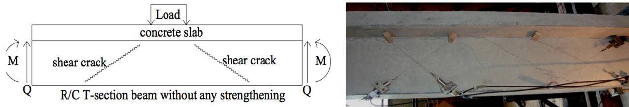
Figure 1. Portion of a R/C T-beam with shear cracks.
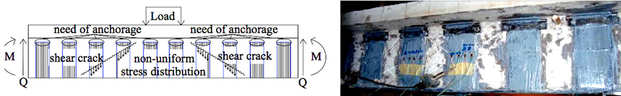
Figure 2. Portion of a R/C T-beam with shear cracks strengthened with external shear reinforcement in the form of open hoop FRP strips.
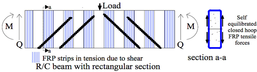
Figure 3. Tensile forces of closed hoop FRP strips applied as shear reinforcement for rectangular R/C beams.
when the shear cracks of a rectangular R/C beam progress the tensile forces that develop on these closed hoop FRP create an internal tensile force system; these tensile forces do not need to be transferred to the volume of the structural member. In this way, such type of external shear reinforcement remains effective until the FRP strip itself is damaged in the form of tensile rupture that usually occurs at the corners of the rectangular section. In order to prohibit such a premature tensile failure these corners must be rounded before the attachment of the FRP strips.
Transfer of Forces That Develop on Open Hoop FRP Strips
In the case of open hoop FRP strips that are applied as shear reinforcement of R/C T-beams the previously described state of internal forces for each FRP strip is no longer valid. As can be seen in Figure 4, the tensile forces that develop on these open hoop FRP strips when the shear cracks of a R/C T-beam progress must be transferred to the concrete volume of the structural member.
The ultimate axial strain values given by the manufacturers of the FRP materials reach values in the range of 2%. Consequently, sheets made by these materials, despite their relatively small thickness which is usually below 0.2 mm for one layer, can develop substantial tensile forces in the direction of their fiber. This property accompanied with their low weight and the very easy external application to structural elements, by attaching them on the external surfaces by proper organic or inorganic matrices, results in their being used as effective longitudinal or transverse reinforcement for such structural elements that are in need of strengthening [10-13]. However, the following limitations exist for this type of application.
The first limitation springs from the fact that the ultimate axial strain value of the order of 2% for the material of the fiber cannot be reached for all the fibers together in a sheet due to the actual conditions of the attachment. The second limitation results from the way the tensile forces which develop on these FRP sheets can be transferred. When the transfer of these forces relies solely on the interface between the FRP sheet and the external surface of the reinforced concrete structural elements, the delamination (debonding) mode of failure of these sheets occurs, due to the relatively low value of either the ultimate bond stress at this interface or the relatively low value of the tensile strength of the underlying concrete volume. This mode of failure is quite common and it occurs in many applications well before the correspond-
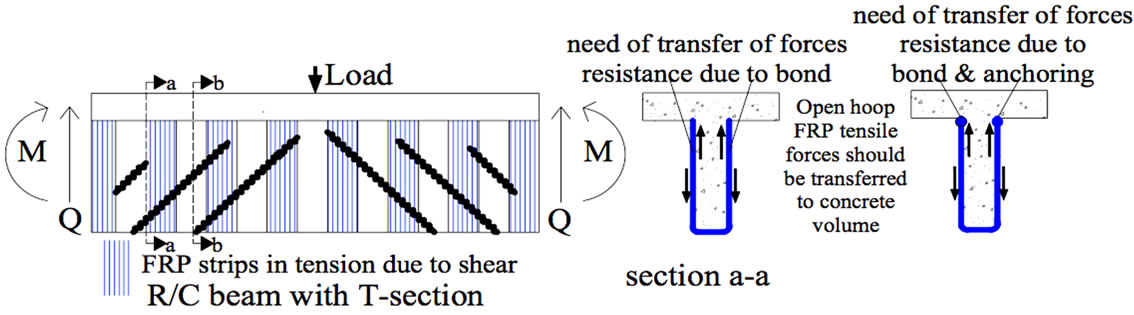
Figure 4. Tensile forces of the open hoop FRP strips applied as shear reinforcement for R/C T-beams.
ing FRP sheets develop tensile axial strains in the neighborhood of values mentioned before as design limit axial strains (approximately of the order of 1%). Consequently, there is a need of alternative ways in order to transfer these tensile forces apart from the simple attachment, in order to enhance the exploitation of the FRP material potential.
The problem of the transfer of forces from the FRP strips has been studied extensively in the past [14-17]. A satisfactory transfer of such forces must rely on either an appropriate length of bondage for the FRP strip or an appropriate anchorage scheme or both. In this way the premature debonding failure of the FRP strip can be avoided. Numerous researchers [18-20] have conducted experiments to study this debonding type of failure and to investigate means for improvement. It was shown that the desired capacity of such an R/C member strengthened with the use of FRP’s can be reached more easily when this debonding type of failure of the FRP sheets is delayed. There is a real necessity to develop reliable anchoring details that can accompany repair and strengthening schemes of R/C elements employing FRP layers in such a way that the FRP parts together with their anchoring detail can provide a feasible and safe solution for such an application. It was shown [4,12,14] that when utilizing mechanical anchors one need not rely on the bond which is provided to the FRP-concrete interface by the use of commercially available epoxy resins.
From the previous discussion it was demonstrated that the transfer of forces from the open hoop FRP strips to the concrete volume is of the utmost importance because the effectiveness of such FRP strips to function as external shear reinforcement depends on the adequacy of the mechanism that is mobilised, either bond and/or anchorage, to transfer these forces having the required amplitude. Full-scale R/C beam specimens have been tested in order to investigate the effectiveness of such transfer mechanism retrofitting schemes employing open-hoop FRP strips as shear reinforcement. By loading these full-scale R/C beam specimens to failure the effectiveness of the employed FRP tensile force transfer mechanisms was investigated. This type of FRP tensile force transfer mechanism validation has been used by the authors by employing full scale R/C beam specimens of either rectangular or T-beam geometry [7,14,21]. However, testing such full scale beam specimens is both expensive as well as cumbersome as it requires the application of large forces as well as special loading arrangements. This is more so if the investigated FRP strip tensile force mechanism (bond and/or anchorage) is at a preliminary stage of development. For this purpose a novel substitute loading arrangement has been devised to examine specifically this FRP strip tensile force mechanism (bond and/or anchorage) in a simplified manner. The following paragraphs discuss the utilization of this simplified novel loading arrangement in studying the way to effectively transfer the open hoop FRP strip tensile force either through bond or through an anchoring scheme.
3. Novel Loading Arrangement
This novel loading arrangement is based on the concept of loading a unit specimen representing the portion of the T-beam depicted in Figure 4 between sections a-a and b-b. This portion of the T-beam is shown in Figure 5; it represents a small part of the full beam specimen with a length of 200 mm, instead of 3000 mm for a full beam specimen. This unit beam specimen can accommodate only one open hoop FRP strip attached to it either by bond and/or by anchoring (Figure 5). The objective is to develop tensile forces on this unit beam specimen with only one open hoop FRP strip similar to the tensile forces that develop on the full T-beam of Figure 4. This is shown in some detail in Figure 5 where it can be seen that the open hoop FRP strip is extended at the bottom face of the R/C T-beam in order to accommodate a steel semi-cylindrical insert. At the same time a small reaction steel frame is attached around the remaining portion of the unit beam specimen. In this way the open hoop FRP strip can be forced in tension against the unit beam portion thus examining the capacity of the tensile force transfer mechanism between the open hoop FRP strip and the concrete portion of the unit beam specimen. As already mentioned, the advantage here is the fact that such unit beam specimens can be constructed in large numbers relatively easily when compared to the construction of the corresponding full T-beam specimens. Moreover, the level of forces required to reach the limit state for the force transfer mechanism between the one open hoop FRP strip and such a unit beam specimen is much smaller than the level of forces required to reach similar limit state for the full beam specimen. Finally, the unit beam specimen with the one open hoop FRP strip attached can be instrumented in detail in order to monitor the development of the stress field at the FRP strips during the various stages of loading as well as the propagation of debonding and the performance of anchoring at the limit state. This cannot be easily monitored in a full beam loading sequence as the exact development of the shear cracking is not predetermined.
3.1. Construction of the Unit Beam Specimens
The tested unit beam prismatic specimens were equal to twenty (20). Each one of these specimens can house one open hoop FRP strip with sufficient width and length (see Figure 5). The basic mechanical properties of the used FRP materials (either CFRP or SFRP) are included in Table 1, as measured by specific laboratory tests.
The concrete mix was kept the same for all specimens with a measured compressive cylindrical strength equal to 22 MPa. The internal reinforcement was utilized to prohibit any accidental failure. Finally, Table 1 summarizes the experimentally measured properties of either CFRP or SFRP. The use of the anchoring device was also utilised selectively.
The previously described novel loading arrangement (Figure 5) was utilized whereby the tensile force is directly applied in the axis of symmetry at the right part of the FRP strips that form an open hoop at this location; the other two sides of the FRP strip are bonded in a symmetric way on the top and bottom side of the concrete prism, as shown in this figure. It must be underlined here that the stress field generated by this novel loading arrangement is relatively symmetric and thus differs from the complex stress field that develops on actual FRP strips when they are attached to R/C structural elements subjected to combined flexure and shear. Despite this, the novel loading arrangement and the corresponding specimens gain significantly in simplicity without losing the most important facts of the FRP strip bond/anchorage force transfer behaviour that is being investigated. During testing, the applied load is measured (attached load cell, Figure 5) together with the longitudinal (axial) strains at four different locations of the external surface of the FRP strip, as indicated in Figure 5 (s.g.1 to s.g.4), in order to measure the stress field that develops at the FRP layer before and during the debonding.
Moreover, the relative longitudinal displacement between the concrete prism and the FRP surface is also monitored using four displacement transducers that are properly attached on the specimen, as indicated in Figure 5, in order to record the initiation and propagation of the debonding of the FRP. Two different types of anchoring
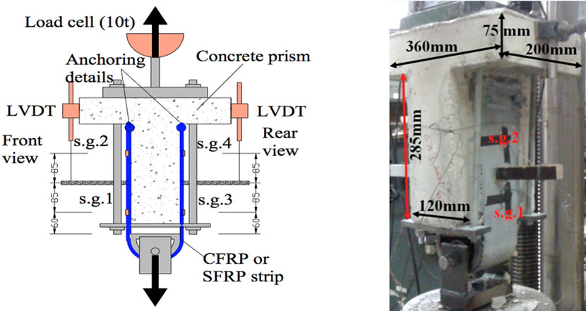
Figure 5. Unit beam specimen with the novel loading arrangement.
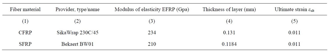
Table 1. Properties of FRP.
devices were investigated. The first utilises an L-shape steel angle and bolts for transmitting the forces to the concrete prism (Figure 6). The second type, which is developed by the Laboratory of Strength of Materials and Structures of Aristotle University of Thessaloniki in Greece and it is patented with patent numbers EP 09386037.7 and WO2011073696 is depicted in Figure 7 [4,18].
In column (1) of Table 2 the specimens are listed with their code names starting with the letter C that denotes a carbon fiber reinforcing polymer strip (CFRP). In column (1) of Table 3 the specimens are listed with their code names starting with the letter S that denotes a steel reinforcing polymer strip (SFRP).
The number of layers of FRP strips utilized in each specimen is denoted by the fourth character of the code name (1 for one layer and 2 for two layers) for each specimen as it is listed in column (1) of either Tables 2 or 3. The use of an anchoring device as well as summary information of the anchoring are provided in columns (2) and (3) of either Tables 2 or 3. The tests were conducted using a 1000 kN capacity hydraulic piston. The measurements of load, displacements and strains were recorded using an automatic data acquisition system.
4. Discussion of the Observed Performance
Summary experimental results are listed in Tables 2 and 3. In these tables, the observed failure mechanism for each specimen is listed in column (8) with the corresponding value of the ultimate measured load listed in column (4). From the strain measurements provided by strain gages 1 and 3 (εs.g.1, εs.g.3) attached on either side of each FRP strip (see Figures 5-7) the maximum axial FRP strain value was obtained (εmax,aver), listed in column (5) of either Tables 2 or 3, using the following Equation (2). The strain values provided by these two strain gages were selected as they were free from influences arising from the FRP strip force transfer at the vicinity of either the anchoring device or of the extreme edges of the open hoop FRP strip.
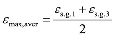 (2)
(2)
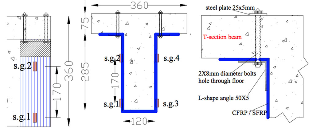
Figure 6. Type 1 anchor.
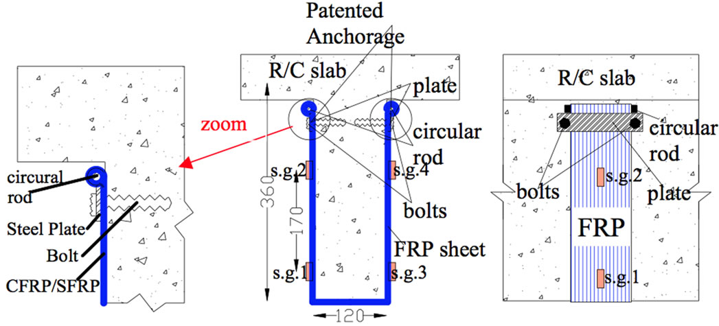
Figure 7. Type 2 anchor.
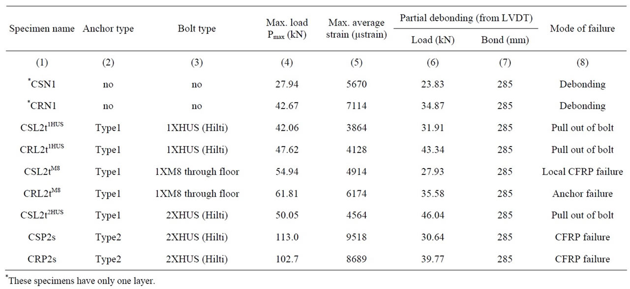
Table 2. Summary of experimental results for specimens utilizing carbon FRP strips.

Table 3. Summary of experimental results for specimens utilizing steel FRP strips.
The initiation of debonding was captured by the measurements of the displacement transducers that were properly attached on the novel loading arrangement (Figure 5). The applied load at the initiation of debonding is listed in column (6). The following observations can be made based on the results included in Tables 2 and 3.
• In the absence of an anchoring device the measured maximum load is not much larger than the load measured during partial debonding. This indicates that the debonding mechanism (Figure 8) is a fast propagating mode of failure. It must be pointed out that the bond length for all open hoop FRP strip specimens was equal to 285 mm except for specimens SNL2tM8-M10, SNL2tM10, SNL2tM12 that were left intentionally without being bonded (see Table 3).
• When an anchoring device is employed, the measured maximum load is always larger than the corresponding maximum load without any anchoring. This is valid even for specimens whose anchoring device (or its bolts) eventually failed during testing (Figure 9).
• For these specimens where failure of the anchoring device (or its bolts) was observed, the measured maximum load is again not much larger than the load of partial debonding.
• For specimens whose anchoring device (or its bolts) did not fail during testing the measured maximum load attained values much larger than for specimens that did not employ an anchoring device at all or for specimens with an anchoring device (or its bolts) that failed during testing.
• The above observations are valid for specimens with open hoop FRP strips made by either carbon (CFRP) or steel (SFRP). It must be pointed out that the used open hoop CFRP strips had an effective area 23.3% larger than the corresponding area of the used open hoop SFRP strips (see Table 1).
• The maximum observed load was equal to 113 KN for specimen CSP2s (Table 2) that utilised 2 layers of carbon FRP strips with the patented anchoring device (Hilti bolts). The second maximum observed load was equal to 105.2 KN for specimen SRP2s (Table 3) that utilised 2 layers of steel FRP strips with the patented anchoring device (Hilti bolts).
• The used open hoop SFRP strips performed equally well during this testing sequence in terms of maximum load capacity. Taking into account the fact that
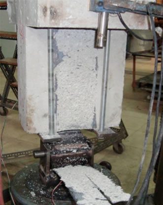
Figure 8. Debonding failure of FRP strip.
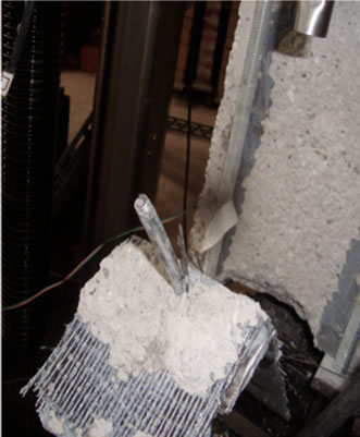
Figure 9. Anchor failure (fracture of bolt).
the CFRP strips had an effective area 23.3% larger than the corresponding SFRP strips this explains the fact that the SFRP strips reached a larger maximum strain value (10,747 μ strains, SRP2s, Table 3) than the corresponding maximum strain value equal to 9518 μstrains for carbon CFRP specimen CSP2s (Table 2).
• The maximum measured load that was achieved utilizing the patented anchoring device is 3.5 to 4 times larger than the maximum load measured when no anchoring device was used and the transfer of tensile forces relied only on 285 mm bond length (on either side of each FRP strip). This fact clearly demonstrates the advantage that can be gained in transferring high tensile forces through such an open hoop FRP strip shear upgrade retrofitting scheme using appropriate anchoring devices.
The maximum measured load as well as the average maximum measured strain results from all tested specimens are also listed in columns (2) and (3) of either Tables 4 or 5. Table 4 lists these results for the carbon FRP strip specimens whereas Table 5 for the steel FRP strip specimens. The code names of each specimen is listed in column (1) as was done in Tables 2 and 3. Utilising the maximum average strain values (εmax,aver, column 3 of Tables 4 or 5) and employing the following Equation (3) a maximum load is calculated that is denoted as Pcal. Aeff denotes the effective area of the used open hoop FRP strip (this value is double to account for the two branches of the open hoop strip) and EFRP is the measured Young’s modulus of the FRP material (Table 1, column 3). The values of the maximum load calculated in this way for each specimen are listed in column (4) of either Table 4 or 5. The ratio of the maximum load measured directly (Pmax, column 2, Tables 4 and 5) over the calculated value Pcal, obtained by employing Equation (3), is listed in column (5) of either Tables 4 or 5.
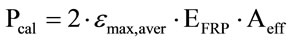 (3)
(3)
As can be seen the values of this ratio are for the majority of these specimens close to 1. This fact increases the confidence in the maximum average FRP strain values (εmax,aver, column 3 of Tables 4 or 5) obtained utilising Equation (2) as explained before. Based on this observation, these measured maximum average strain values will be used to define a material exploitation index (MEI). The values of this index are obtained by dividing the measured maximum average strain values (εmax,aver) with the measured ultimate strain values εult (listed in Table 1, column 5) using the following relationship (Equation (4)):
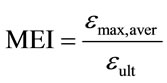 (4)
(4)
The higher the value of this index (MEI) signifies that
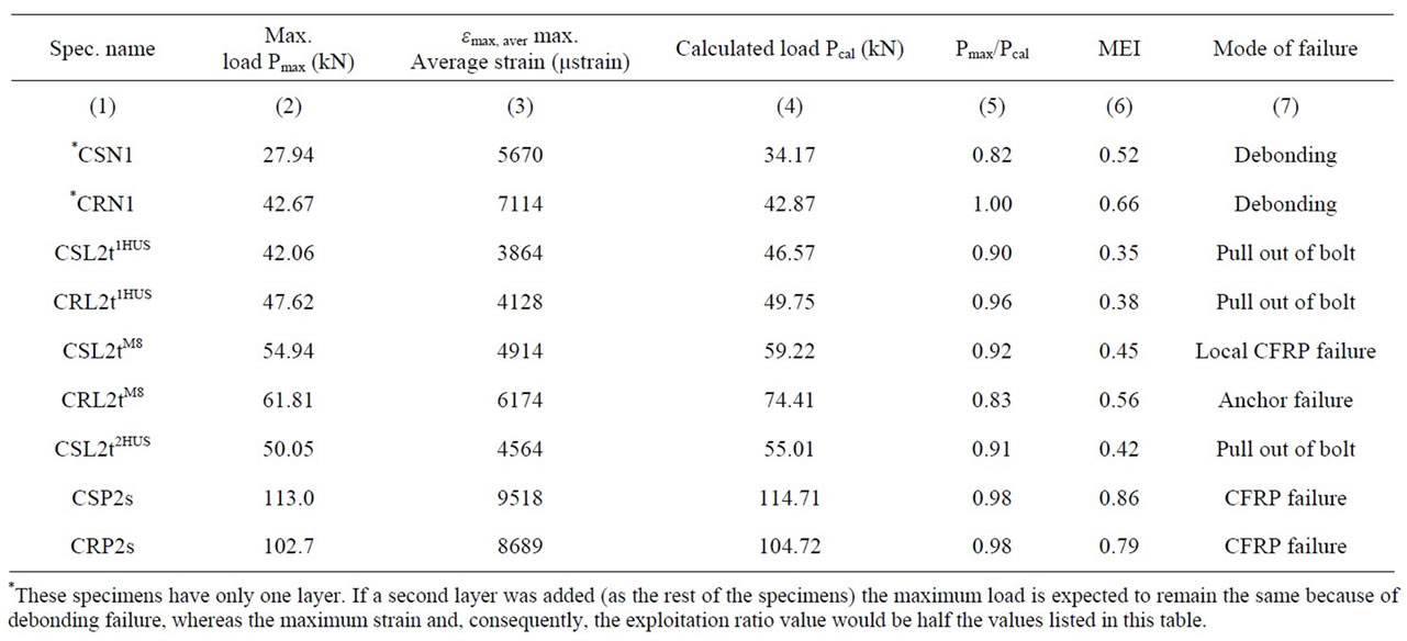
Table 4. Summary results including values of Pcal and MEI for specimens utilizing carbon FRP strips.
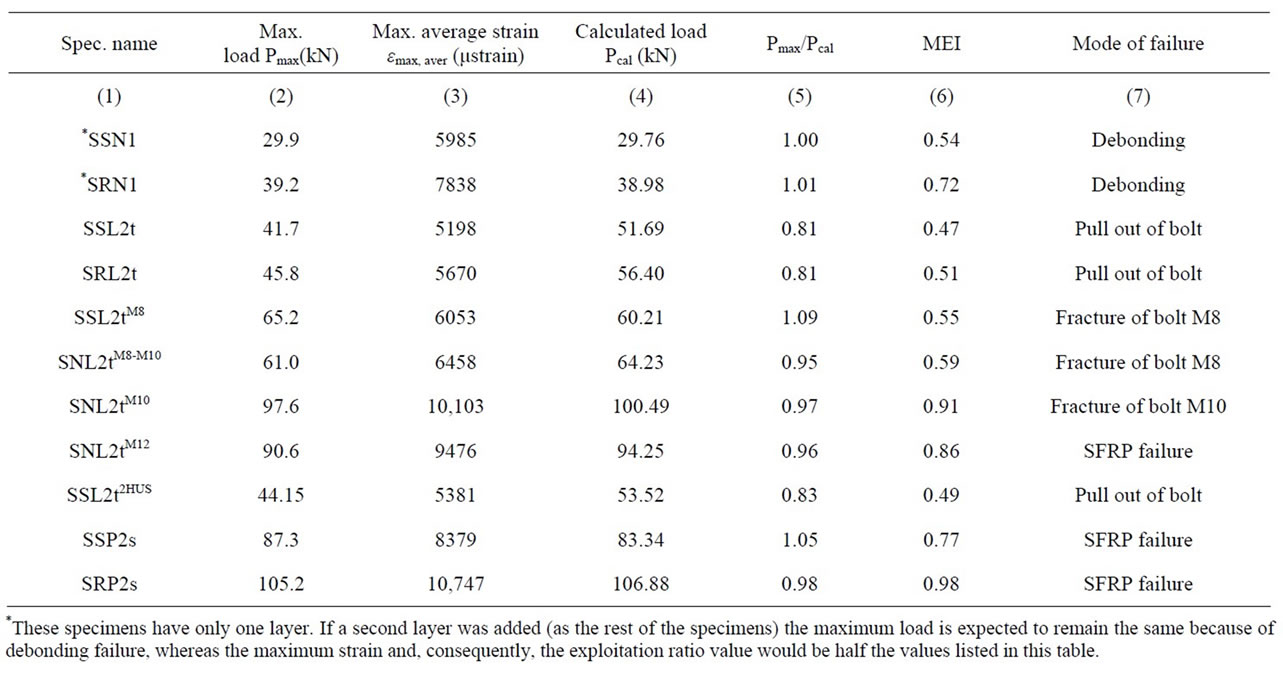
Table 5. Summary results including values of Pcal and MEI for specimens utilizing steel FRP strips.
better exploitation of the FRP material is achieved, as the open hoop FRP strip reaches strain values that are closer to the ultimate strain for the material, as was measured with specific coupon tests in the laboratory. High values of this material exploitation index signify that the open hoop FRP strip reaches strain values nearing the material ultimate measured strain and in this case it is expected that fracture of the FRP strip is imminent (column 7, Tables 4 or 5 and Figure 10).
On the contrary, relatively small values of this MEI index indicate that a premature failure of the open hoop FRP strip system takes place, either because of debonding (Figure 8) or because of improper performance of the anchoring device (Figure 9). In this case, a better use of the FRP material is also indicated, by either better bonding (increase in the bond length up to a point) or use of a properly designed anchoring device, that will lead to a higher than before MEI value.
5. Conclusions
1) For specimens whose anchoring device (or its bolts)
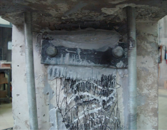
Figure 10. Fracture of SFRP strip properly anchored.
did not fail during testing the measured maximum load attaining values much larger than for specimens that did not employ an anchoring device at all or for specimens with an anchoring device (or its bolts) that failed during testing.
2) The maximum measured load that was achieved utilizing the patented anchoring device is 3.5 to 4 times larger than the maximum load measured when no anchoring device was used and the transfer of tensile forces relied only on 285 mm bond length (on either side of each FRP strip). This fact clearly demonstrates the advantage that can be gained in transferring high tensile forces through such an open hoop FRP strip shear upgrade retrofitting scheme using appropriate anchoring devices.
3) The used open hoop SFRP strips performed equally well or even slightly better during this testing sequence in terms of maximum load capacity. Thus, it can be claimed that this particular type of steel reinforcing plastic material used in this investigation can also be successfully employed for this shear type retrofitting scheme.
4) A material exploitation index was defined. The higher the value of this index (MEI) signifies that better exploitation of the FRP material is achieved, as the open hoop FRP strip reaches strain values that are closer to the ultimate strain for the material. On the contrary, relatively small values of this MEI index indicate that a premature failure of the open hoop FRP strip system takes place, either because of debonding or because of improper performance of the anchoring device. This can be corrected by a better design of the open hoop FRP strip retrofitting scheme.
5) The utilisation of the novel loading arrangement together with the unit beam specimens was shown, despite certain limitations, to be very successful in demonstrating the advantages and limitations in the open hoop FRP strip transfer force mechanisms that were investigated, which is the efficiency of the bond and/or the anchoring device. Such a novel loading arrangement can be utilized for proof testing of such open hoop FRP strip retrofitting schemes.
6. Acknowledgements
• Partial financial support for this investigation was provided by the Hellenic Earthquake Planning and Protection Organization (EPPO), which is gratefully acknowledged.
• Carbon fibers and epoxy resins were provided by Sika Hellas.
• Steel fibers are not commercially available and were provided for the present study by Bekaert Industries.
• One of the anchoring devices employed in this study (Figure 7) is patented under the no. EP 09386037.7, or WO2011073696.
REFERENCES
- G. C. Manos, “Consequences on the Urban Environment in Greece Related to the Recent Intense Earthquake Activity,” International Journal of Civil Engineering and Architecture, Vol. 5, No. 12, 2011, pp. 1065-1090.
- Eurocode-8, “Design of Structures for Earthquake Resistance, Part 2: Bridges,” European Committee for Standardization, 2004.
- Organization of Earthquake Planning and Protection of Greece (ΟΑSP), “Guidelines for Retrofitting in Reinforced Concrete Buildings,” Athens, 2011.
- G. C. Manos, K. Katakalos and V. Kourtides, “Construction Systeme for Strengthening an Existing Structure with Tension Sheets and a Respective Anchoring Device and Method Therefore,” Patent No: EP2336455-(A1), 2011.
- ACI 440.2R-08, “Guide for the Design and Construction of Externally Bonded FRP Systems for Strengthening Concrete Structures,” American Concrete Institute, 2008.
- C. Bakis, et al., “Fiber-Reinforced Polymer Composites for Construction-State of the Art Review,” Journal of Composites of Construction, Vol. 6, No. 2, 2002, pp. 73- 87.
- K. Katakalos, G. C. Manos and C. G. Papakonstantinou, “Comparison between Carbon and Steel Fiber Reinforced Polymers with or without Anchorage,” Proceedings of 6th International Conference on FRP Composites in Civil Engineering, Rome, 2012.
- K. Katakalos, “Strengthening of R/C Structures under High Cycle Fatigue Loadings,” LAP Lambert Academic Publishing GmbH & Co. KG, 2009.
- C. G. Papakonstantinou and K. Katakalos, “Flexural Behavior of Reinforced Concrete Beams Strengthened with a Hybrid Retrofit System,” Structural Engineering and Mechanics, Vol. 31, No. 5, 2009, pp. 225-252.
- K. Katakalos and C. Papakonstantinou, “Fatigue of Reinforced Concrete Beams Strengthened with Steel Reinforced Inorganic Polymers,” Journal of Composite for Construction, Vol. 13, No. 2, 2009, pp. 103-112. doi:10.1061/(ASCE)1090-0268(2009)13:2(103)
- G. C. Manos, K. Katakalos and C. Papakonstantinou, “Shear Behavior of Rectangular Beams Strengthened with Either Carbon or Steel Fiber Reinforced Polymers,” Applied Mechanics and Materials, Vol. 82, 2011, pp. 571- 576. doi:10.4028/www.scientific.net/AMM.82.571
- G. C. Manos, K. Katakalos and V. Kourtides, “Study of the Anchorage of Carbon Fiber Plastics (CFRP) Utilized to Upgrade the Flexural Capacity of Vertical R/C Members,” Proceedings of 14th WCEE, Beijing, 2008, pp. 1079-1095.
- G. C. Manos and K. Katakalos, “The Use of Fiber Reinforced Plastic for the Repair and Strengthening of Existing Reinforced Concrete Structural Elements Damaged by Earthquakes,” Fiber Reinforced Polymer—The Technology Applied for Concrete Repair, Martin Alberto Masuelli, 2013.
- J. F. Chen and J. G. Teng, “Shear Capacity of Fiber-Reinforced Polymer-Strengthened Reinforced Concrete Beams: Fiber Reinforced Polymer Rupture,” Journal of Structural Engineering, Vol. 129, No. 5, 2003, pp. 615-625. doi:10.1061/(ASCE)0733-9445(2003)129:5(615)
- C. Papakonstantinou, K. Katakalos and G. C. Manos, “Reinforced Concrete T-Beams Strengthened in Shear with Steel Fiber Reinforced Polymers,” Proceedings in 6th International Conference on FRP Composites in Civil Engineering, 2012, Rome, pp. 672-695.
- G. C. Manos, K. Katakalos and V. Kourtides, “Cyclic Behaviour of a Hybrid Anchoring Device Enhancing the Flexural Capacity and Ductility of an R/C Bridge-Type Pier Strengthened with CFRP Sheets,” Journal of Civil Engineering Research, Vol. 3 No. 1, 2013, pp. 52-64.
- A. Khalifa and A. Nanni, “Rehabilitation of Rectangular Simply Supported RC Beams with Shear Deficiencies Using CFRP Composites,” Construction and Building Materials, Vol. 16, No. 3, 2002, pp. 135-146. doi:10.1016/S0950-0618(02)00002-8
- G. C. Manos, K. Katakalos and V. Kourtides, “Construction Structure with Strengthening Device and Method,” European Patent Office, Patent Number: WO2011073696, 2011.
- G. C. Manos, K. Katakalos and V. Kourtides, “The Influence of Concrete Surface Preparation When Fiber Reinforced Polymers with Different Anchoring Devices Are Being Applied for Strengthening R/C Structural Members,” Applied Mechanics and Materials, Vol. 82, 2011, pp. 600-605. doi:10.4028/www.scientific.net/AMM.82.600
- G. C. Manos, K. Katakalοs, G. Koidis and C. G. Papakonstantinou, “Shear Strengthening of R/C Beams with FRP Strips and Novel Anchoring,” Journal of Civil Engineering Research, Vol. 2, No. 6, 2012, pp. 73-83.
- G. C. Manos, K. Katakalos, C. Papakonstantinou and G. Koidis, “Enhanced Repair and Strengthening of Reinforced Concrete Beams Utilizing External Fiber Reinforced Polymer Sheets and Novel Anchoring Devices,” Proceeding of 15th WCEE, 2012, Portugal, pp. 789-801.