Open Journal of Civil Engineering
Vol. 2 No. 4 (2012) , Article ID: 25238 , 8 pages DOI:10.4236/ojce.2012.24027
3D FE Analysis of Effect of Ground Subsidence and Piled Spacing on Ultimate Bearing Capacity of Piled Raft and Axial Force of Piles in Piled Raft
1Department of Civil Engineering, Chulalongkorn University, Bangkok, Thailand
2Department of Civil and Earth Resources Engineering, Kyoto University, Kyoto, Japan
Email: tranvantuan567@gmail.com
Received September 20, 2012; revised October 22, 2012; accepted November 4, 2012
Keywords: Ground Subsidence; Piled Raft; Piled Spacing; Bearing Capacity; Axial Force; 3D FE Simulation
ABSTRACT
The effects of ground subsidence and piled spacing on axial force of piles in squared piled rafts were investigated using numerical analysis. Two cases of piled rafts in soft clay including case 1 (s = 2d) and case 2 (s = 4d) with s and d were piled spacing and piled diameter respectively were considered in this study. Undrained (without ground water pumping) and drained (with ground water pumping) conditions were applied in each case in order to evaluate variations of ultimate bearing capacity of piled raft and axial force of the piles in piled raft. The results showed that ultimate bearing capacity increased about 25% for undrained condition and about 32% for drained condition when piled spacing increased from 2d to 4d. In the same piled spacing, axial force of the piles increased about 9% for piled spacing of 2d and 7% for piled spacing of 4d when drained condition was applied. When piled spacing increased 2 times (2d to 4d), the axial force of piles increased about 7% for undrained condition and about 5% for drained condition.
1. Introduction
Piled raft foundations are widely used for civil structures such as in [1-4]. The use of piled rafts in settling soils has been faced with many problems such as the changing in bearing capacity and variation of load sharing between piles and raft, total and differential settlements may be affected.
Some research papers relating to ground subsidence have been published in the literature. Among them, [5-7] pointed out some effects of ground subsidence on bearing capacity and differential settlement of foundation. They also emphasized some cities in which the ground subsidence have occurred with high rate (e.g. Bangkok, Ho Chi Minh, Shanghai, Mexico, etc.). The reason for the ground subsidence comes from the pumping of ground water for water supply.
The objective of this study focuses on investigating that whether the ultimate bearing capacity of piled rafts and the axial forces of piles in piled rafts change or not under the effects of ground subsidence and piled spacing. The research was conducted by using 3D FE analysis with Plaxis 3D Foundation Version 2.0.
In analysis, ground subsidence caused by ground water pumping was simulated by drained condition and normal condition was simulated by undrained condition. Vertical distribution load was applied to the surface of the raft. The effects of ground subsidence and piled spacing were figured and some discussions were given in this study.
2. FE Modelling of Piled Rafts
2.1. Geometry of Foundation
A 2.8 × 2.8 × 0.75 m piled raft with 4 piles was considered in this study. To reduce the calculation time, only one-quarter of the foundation was modeled, using symmetry boundary conditions. To enable any possible mechanism in soft clay and to avoid any influence of the outer boundary, the model was extended in both horizontal directions to a total width of 10 m. Figure 1 shows the geometry of foundation and soil in FE analysis.
2.2. Properties of Soil and Foundation
Only one layer of soft clay was simulated in this analysis. The calculation was done by plastic analysis with effective parameters. Undrained and drained conditions were considered in the analysis. Table 1 shows the properties of soft clay. Young modulus of soft clay was increased
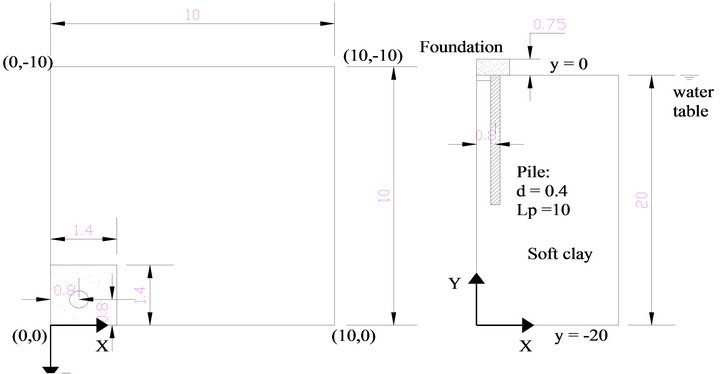
Figure 1. Geometry of foundation and soil in FE analysis (unit: m).
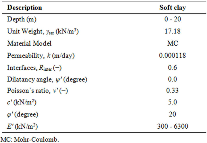
Table 1. Properties of soft clay for FE analysis.
with depth, starting at yref = −0.25 m, and the increment was 300 kN/m2. The properties of piles and raft are presented in Tables 2 and 3 respectively.
2.3. Applied Load
The effect of seflweight of foundation was ignored by assigning the unit weight of raft and piles equal to zero. The foundations was firstly applied a load of 1500 kPa in order to estimate the ultimate bearing capacity.
Based on the result in Table 4, a load of 96 kPa calculated from ultimate bearing capacity of case 1 (for undrained condition) with FS of 2 was applied to all cases to investigate the behavior of the foundation in ground subsidence condition under working load. Figure 2 presents the loading type which was applied in the analysis for both case 1 and case 2. The time considered in the analysis was 18,250 days (or 50 years).
2.4. Details of Simulation
A borehole was used to assign information of soil layer
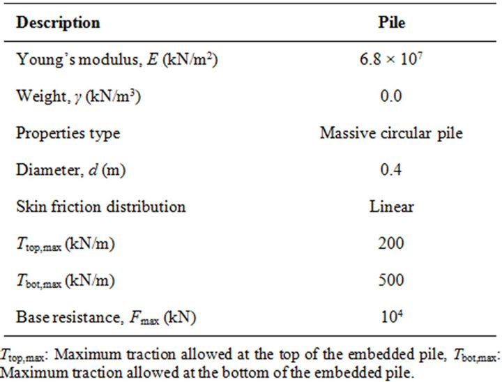
Table 2. Properties of piles (embedded pile).
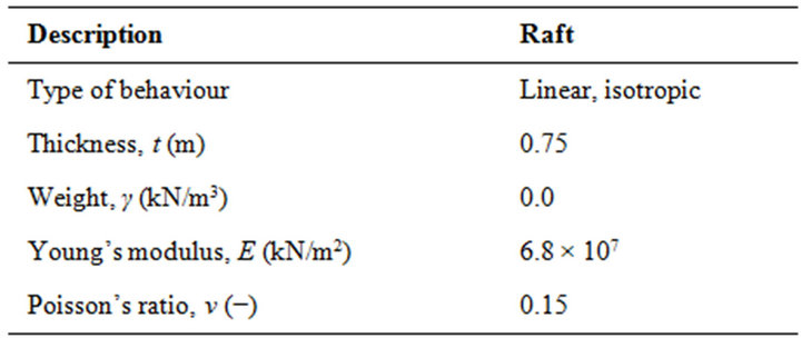
Table 3. Properties of raft (floor).
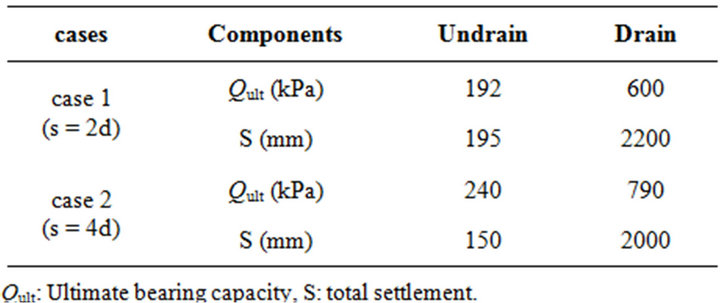
Table 4. Variation of ultimate bearing capacity.
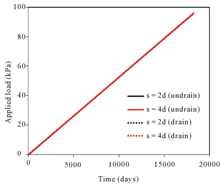
Figure 2. Applied load for case 1 and case 2.
and location of water table. The properties of soil layers in Table 1 were inputted to material data set and the location of water table was defined at the ground surface (y = 0). The raft was simulated by floor element and the properties were given in Table 2. The piles were simulated by embedded piles and the properties in Table 3 were used.
Figure 3 shows the simulation of piled raft foundation in FE analysis. The global coarseness of the mesh in horizontal as well as vertical directions was set to fine. 2D finite element mesh was generated before generating a full 3D mesh. The 2D mesh generation process was based on a robust triangulation principle that searched for optimized triangle and which resulted in unstructured mesh. Large displacement gradients were expected around and under the raft and the piles. Hence, refine cluster was done for the raft and piles to have finer mesh. The 3D mesh composed of 15-node wedge elements was created by connecting the corners of the 2D triangular elements to the corresponding points of the corresponding elements in the next work plane. A total of 4472 elements and 13,044 nodes were created after generating the mesh.
The interfaces (Rinter) were taken as 0.6 for soft clay. Initial stresses were generated by using K0 Procedure in which the default value of K0 was based on Jaky’s formula. Construction stages was followed the type of load (Figure 2) and plastic was used for calculation type. Drained condition in material type was selected for the soil when simulating ground water pumping condition.
3. Results and Discussions
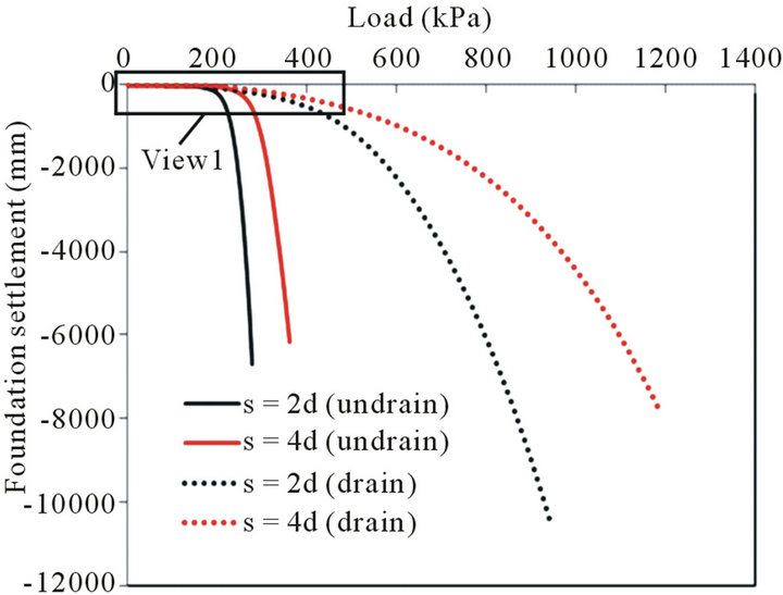
Figure 4 shows load-settlement curves of piled rafts in ground subsidence condition for case 1 (s = 2d) and case 2 (s = 4d). The ultimate bearing capacity of piled raft foundations changed under effect of ground subsidence and piled spacing (Figure 4(a)).
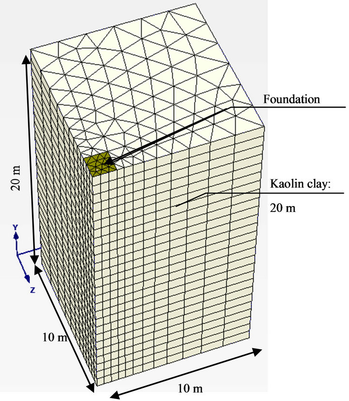
Figure 3. Simulation of piled raft in soft clay.
In both case 1 and case 2, when piled spacing increased from 2d to 4d, the bearing capacity of piled rafts increased in both undrained and drained conditions. For example, at the settlement of 50 mm (Figure 4(b)), the bearing capacity of piled raft increased about 27% for undrained condition and about 22% for drained condition when piled spacing increased from 2d (0.4 m) to 4d (0.8 m). For ultimate bearing capacity, it increased about 25% for undrained condition and about 32% for drained condition when piled spacing increased from 2d to 4d.
More details about the variation of ultimate bearing capacity was described as below: For undrained condition, ultimate bearing capacity was around 192 kPa (at the settlement of 195 mm) for case 1 and was around 240 kPa (at the settlement of 150 mm) for case 2. For drained condition, the ultimate bearing capacity increased largely with the increase of foundation settlement. The ultimate bearing capacity was around 600 kPa (at the settlement of 2200 mm) for case 1 and was around 790 kPa (at settlement of 2000 mm) for case 2. There were switching points (Figure 4(c)) at which two curves (undrained and drain conditions) in each case intersected. The switching point occurred at bearing capacity of 160 kPa and settlement at 41 mm for case 1 while at bearing capacity of 206 kPa and settlement of 46 mm for case 2. Switching point owned a meaning that if the applied load was smaller than the bearing capacity of switching point, the bearing capacity of piled raft decreased in drained condition. When the applied load was larger than the bearing capacity of switching point, the bearing capacity of piled raft increased.
Figure 5 shows the variation of load-settlement curves for the applied load with FS = 2. It was agreed well with
 (a)
(a)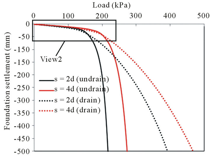 (b)
(b)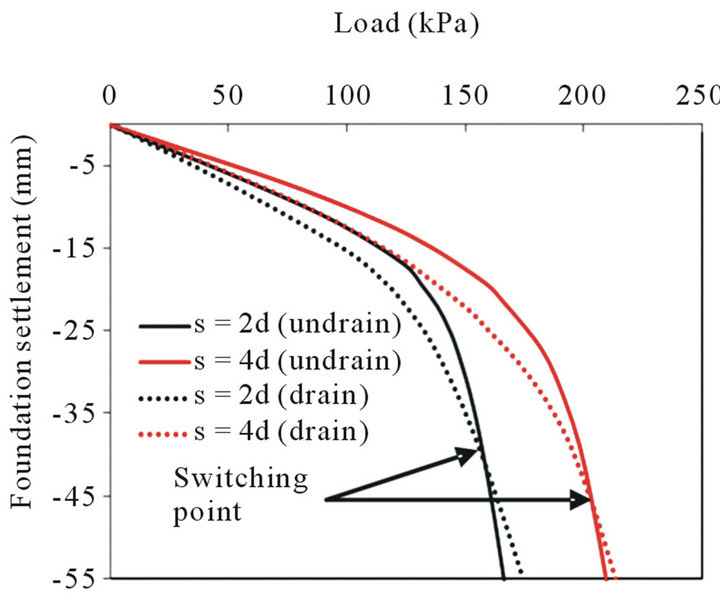 (c)
(c)
Figure 4. Load-displacement curves for piled rafts (Qult) rafts (FS = 2). (a) Load-settlement curves (full view); (b) View 1; (c) View 2.
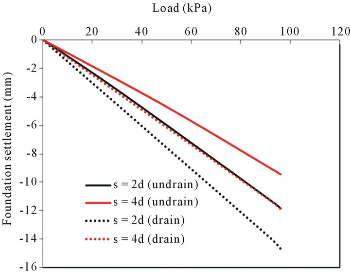
Figure 5. Load-displacement curves for piled.
above discussions, the bearing capacity of piled rafts decreased during drained condition for both case 1 and case 2. When piled spacing increased from 2d to 4d, the bearing capacity of the foundations increased in both undrained and drained conditions.
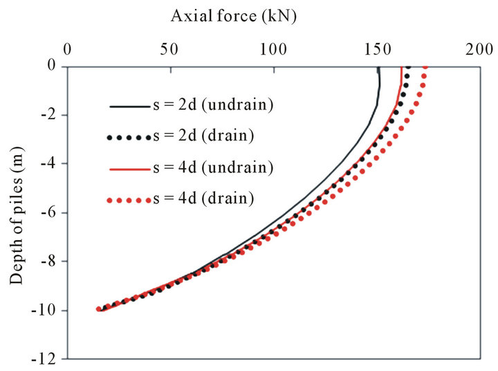
Variation of axial forces with depth was presented in Figure 6. The axial force increased when drained condition was applied (Figure 6(a)). When piled spacing increased from 2d to 4d, the axial force also increased. For example, in the same piled spacing, axial force of the piles increased about 9% for piled spacing of 2d and 7% for piled spacing of 4d when drained condition was applied. When piled spacing increased 2 times (2d to 4d), the axial force of piles increased about 7% for undrained condition and about 5% for drained condition. A part of view of piled load share from the ground surface to a depth of 5 m was presented in Figure 6(b) for easy evaluation.
Distribution of skin friction along pile’s shaft was shown in Figure 7(a). Figure 7(b) shows a part view of skin friction with depth of 5 m. The skin friction increased when drained condition was applied and increased when piled spacing increased between 2d to 4d.
 (a)
(a)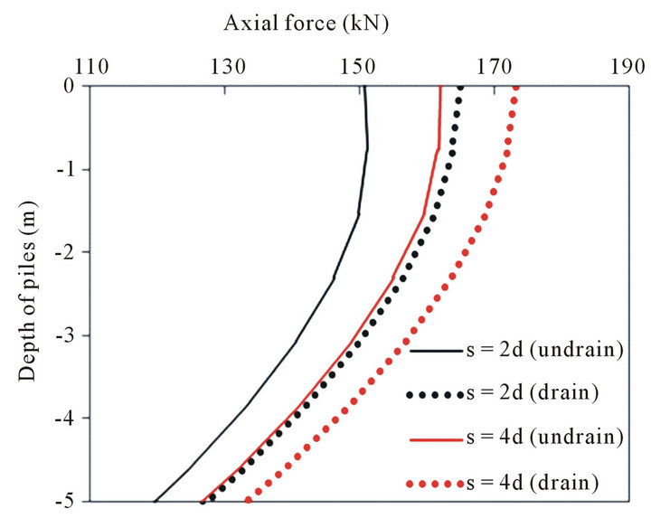 (b)
(b)
Figure 6. Distribution of axial force with depth. (a) Full view of distribution of axial force with depth; (b) A part of view from surface to depth of 5 m.
The increments of skin friction were quite small as shown in Figure 7(b).
Figure 8 shows the variation of load carried by the piles (piled load share) in piled raft foundations. When
 (a)
(a)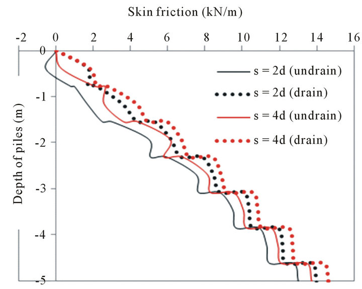 (b)
(b)
Figure 7. Variation of skin friction along pile’s shaft. (a) Full view of distribution of skin friction with depth; (b) A part of view from surface to depth of 5 m.

Figure 8. Variation of piled load share.
the drained condition was applied, the load carried by the piles increased. The soil under beneath the raft was settled resulting the decreased of the contact pressure under the raft and therefore decreased load shared by the raft. The total load was a constant value, so the load was transferred to the piles causing the increase of the load carried by the piles.
When the piled spacing increased (Figure 8), the load shared by the piles also increased. This phenomenon occurred because the soil around the piles was mobilized to resist the applied load. When piled spacing was increased, the stress in mobilized zone was not overlapped resulting larger capacity was carried by the piled. Table 5 summarizes the load sharing between piles and raft and the settlement of the foundations in undrained and drained conditions.
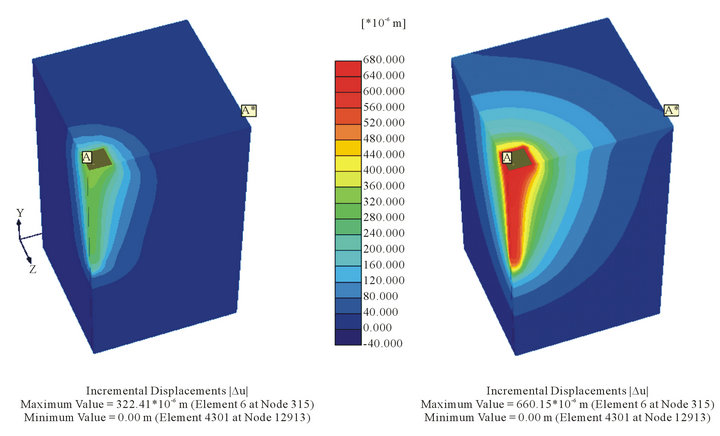
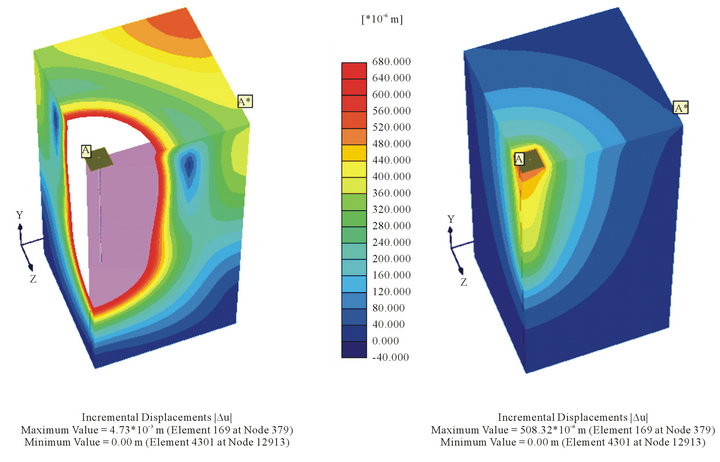
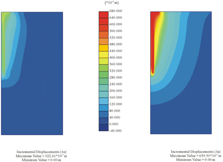
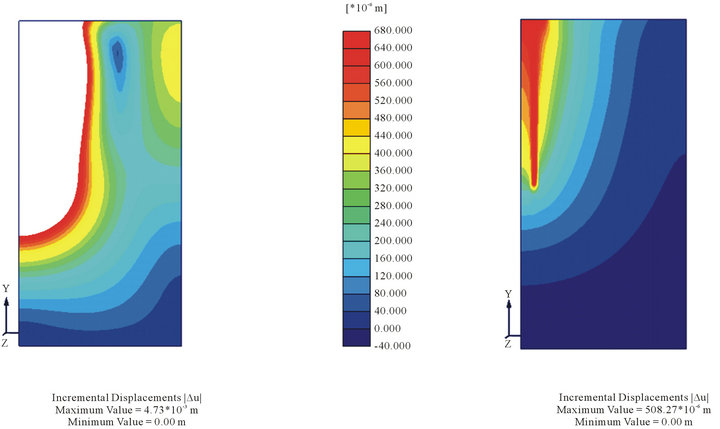
To compare the failure mechanism between case 1 and case 2 as well as between undrained and drained conditions, the failure mechanism (total incremental displacement) was plotted in the same scaling factor. Comparisons of failure mechanism between undrained and drained conditions in case 1 and case 2 were presented in Figures 9 and 10 respectively. Sections (A-A*) through the positions of the piles were conducted to evaluate the failure mechanism of the soil around the piles as shown in Figures 11 and 12. A large total incremental displacement zone occurred in drained condition.
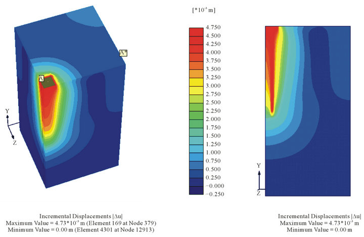
The undrained condition of case 2 was also plotted in real scaling factor to observe the failure mechanism of the soil around the piles. Figure 13 shows the failure mechanism of the undrained condition of case 2 in real scaling factor. The total incremental displacement developed around the pile with large at piled head and decreased at piled tip.
4. Conclusions
For the effect of undrained and drained conditions, the ultimate bearing capacity of the foundation was increased with the increase of foundation settlement in drained condition. When the value of applied load was smaller than the bearing capacity of switching point in load-settlement curve, the bearing capacity of piled raft de-
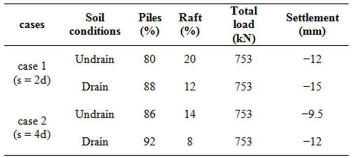
Table 5. Load sharing between piles and raft.
 (a) (b)
Figure 9. Failure mechanism of case 1 (s = 2d). (a) Undrain; (b) Drain.
 (a) (b)
Figure 10. Failure mechanism of case 2 (s = 4d). (a) Undrain; (b) Drain.
 (a) (b)
Figure 11. Sections through pile’s position in case 1 (s = 2d). (a) Undrain; (b) Drain.
 (a) (b)
Figure 12. Sections through pile’s position in case 2 (s = 4d). (a) Undrain; (b) Drain.
 (a) (b)
Figure 13. Failure mechanism of case 2 (undrained condition) in real scaling factor. (a) Full view; (b) Section A-A*.
creased under drained condition. When the value of applied load was larger than the bearing capacity of switching point in load-settlement curve, the bearing capacity of piled raft increased with the increase of foundation settlement. The axial force of piles in piled raft was increased under drained condition for the case of applied load with FS = 2.
For the effect of piled spacing, ultimate bearing capacity increased when piled spacing increased from 2d to 4d in both undrained and drained conditions. When piled spacing increased (2d to 4d), the axial force of piles also increased in both undrained and drained condition.
5. Acknowledgements
This paper was carried out under the advisers of Prof. M. Kimura and Assoc. Prof. T. Boonyatee. The research work was partially supported by AUN/SEED Net—JICA. Author would like to thank to advisers, reviewers and AUN/SEED Net Program.
REFERENCES
- E. Franke, Y. EL-Mossallamy and P. Wittmann, “Calculation Methods for Raft Foundations in Germany. Design Applications of Raft Foundations,” Thomas Telford, London, 2000, pp. 283-322.
- Y. C. Tan, C. M. Chow and S. S. Gue, “Piled Raft with Short Piles for Low-Rise Buildings on Very Soft Clay,” Proceedings of 15th SEAGC, Bangkok, 2004, pp. 171- 176.
- Y. C. Tan, S. W. Cheah and M. R. Taha, “Methodology for Design of Piled Raft for 5-Story Buildings on Very Soft Clay. Foundation Analysis and Design: Innovative Methods,” Geotechnical Special Publication (ASCE), Vol. 153, 2006, pp. 226-233.
- R. Katzenbach, U. Arslan and C. Moormann, “Piled Raft Foundations Projects in Germany. Design Applications of raft Foundations,” Thomas Telford, London, 2000, pp. 323-392.
- H. G. Poulos, “A Practical Design Approach for Piles with Negative Friction,” Proceedings of the Institution of Civil Engineers, Geotechnical Engineering, Vol. 161, No. 1, 2008, pp. 19-27. doi:10.1680/geng.2008.161.1.19
- V. T. Le and T. M. D. Ho, “Measuring Ground Subsidence in Ho Chi Minh City Using Differential in SAR Techniques,” Science & Technology Development, Vol. 11, No. 12, 2008, pp. 121-130.
- N. Phienwej, S. Thepparak and P. H. Giao, “Prediction of Differential Settlement of Buildings Induced by Land Subsidence from Deep Well Pumping,” 15th Southeast Asian Geotechnical Society Conference, Bangkok, 2004, pp. 165-170.