Modern Instrumentation
Vol. 1 No. 4 (2012) , Article ID: 23671 , 4 pages DOI:10.4236/mi.2012.14007
Results of the Measurement of the Collimator Hole Angulation for Different Collimators of SPECT with Adaptive Quality Control Phantom
1Agricultural, Medical and Industrial Research School, Nuclear Science and Technology Research Institute, Karaj, Iran
2Department of Physics, Peyambare Azam Institute, Islamic Azad University of Tehran, Tehran, Iran
Email: *hzeinali@nrcam.org
Received August 7, 2012; revised September 16, 2012; accepted September 29, 2012
Keywords: Nuclear Medicine; Adaptive Quality Control Phantom; Collimator hole Angulation
ABSTRACT
The Adaptive Quality Control Phantom (AQCP) is the computer-controlled phantom which positions and moves a radioactive source in the Field of View (FOV) of an imaging nuclear medicine device on a definite path to produce any spatial distribution of gamma rays to perform the QC Tests such as the Collimator Hole Angulation (CHA) of Single Photon Emission Computer Tomography (SPECT). The collimator hole angulation for seven collimators were measured with the method by using a point source and computer-controlled cylindrical positioning. In this method the displacement of the image of a point source examined as the AQCP move point source vertically away from the collimator face. The results of the high-accuracy measurement method of CHA show that the measurement accuracy for absolute angulation errors is better than ±0.024˚. The Root Mean Square (RMS) of CHA for LEHR, LEHS, LEUHR, MEGP-250, MEGP-300, MEGP-360 and HEPH collimators of SMV dual heads camera were measured to be 0.290˚, 0.292˚, 0.208˚, 0.194˚, 0.181˚, 0.177˚, 0.150˚, respectively. The Root Mean Square (RMS) of CHA for LEGP, MEGP and HEGP collimators of GE Millennium MG were measured to be 0.154˚, 0.220˚ and 0.202˚ respectively. It is to be added in this connection that the measured RMS of CHA for LEHR collimator with the distance variation from the collimator’s surface +/– 1 mm has been varied +/– 0.04 degree.
1. Introduction
Single Photon Emission Computed Tomography (SPECT) has a number of advantages over conventional Nuclear Medicine (NM) imaging: Contrast improvement and Total volume imaging [1-6]. In order to realize these advantages, rigorous QC procedures must be performed on a routine basis. Important considerations for tomography, unlike planar imaging, include flood field uniformity and Center of Rotation (COR) correction/verification and Collimator Hole Angulation (CHA) [1,4,7,8]. For SPECT imaging, the angulation of the holes in parallel hole collimator must be known in order to ensure its proper set up during a tomographic acquisition, i.e., its holes must be perpendicular to the Axis of Rotation [2,4,6]. There are different methods for evaluating hole angulation [1-3,6,7]. But the one which is a quantitative method and was used by the authors is the displacement of the image of a point source examined as the source is moved vertically away from the collimator face. To apply such method, it is necessary to use a phantom like Adaptive Quality Control Phantom (AQCP) which will support the source at two vertical distances from the collimator face to ensure the accurate alignment of the source [2,4]. We tried to measure CHA of three low energy collimators with more accuracy by AQCP method.
In the reconstruction of images from projections during a SPECT acquisition, it is assumed that image matrix, representing the activity distribution in a section, has a constant relationship to the data acquisition matrix [2,4,5,8]. If one matrix shifts to the other for different angles of data acquisition, then the image reconstructed from back projecting the data will be blurred because of the relative motion of the two matrixes [2,8]. The elements contributing to COR consist of mechanical problems with detector rotation, changes in amplifier gain and offset, problem with head tilt, collimator hole angulation, errors in the analog to digital converter, as well as the lack of parallelism between the collimator/detector plane and the axis of rotation [4]. In the IAEA-TECDOC-602 method of COR evaluation, the constant shift of COR correction was measured and applied [8]. We tried to measure dynamic mechanical rotation error of gamma camera SPECT by evaluating the results of COR with IAEATECDOC-602 and AQCP methods.
AQCP was designed to perform a uniform set of procedures that can be used for routine quality control of a scintillation camera-based system. AQCP is an electromechanical device designed to acquire the field uniformity, center of rotation and collimator hole angulation by using some advanced methods of position control [9,11-13]. In order to use AQCP to simulate QC phantoms, the device moves a radioactive source within the Field of View (FOV) of the NM imaging device on a definite path to produce a three-dimensional artificial distribution of γ rays [10,12,14]. AQCP, in fact, can be used to optimize QC tests for the measurement of uniformity, resolution, linearity, absolute size of pixel and center of rotation and can perform the total performance test of Single Photon Emission Computer Tomography (SPECT) [12-14].
2. Materials and Methods
AQCP design and structure: AQCP is structured of different parts comprising mechanical, electrical and is equipped with hardware and software systems. From mechanical perspective, the cylindrical coordinates is chosen as a pattern for the motion and simulation of AQCP [9,10,12,13]. A combination of ball screw and reel system is used to position the point source in any desired point in space with a precision of 0.06 mm (Figure 1). Two step motors are used; each of them is connected to a gear box and divides each complete turn into 2000 steps (0.18 degree/step). The accuracy of step motor is 10% (0.018 degree/step). To achieve the Z and θ (two dimensions of the cylindrical coordinates), by the AQCP software, the ball screw system was used (Figure 1). Ball screw consists of a precise screw with a step of 1mm and a wide nut (with length of 4 cm) (Figure 1(C)). Another small nut was put under the wide nut. The θ parameter is adjusted by changing the position of the small nut and fixing it to the wide nut. When the small nut is open, the system can give different Z’s. So, in this system the Z and θ can be adjusted manually (Figure 1(C)) and generally small nut is closed when the AQCP is operating. To reach r (third dimension of the cylindrical coordinates), the related motor (motor No. 2 In Figure 1(B)) rotates the reel and the roll. A complete round of the reel (30 mm) is 500 steps, as result; the precision of transverse radius of cylindrical coordinates (r) is 0.06 mm (Figure 1(B)). From electrical stand point, AQCP is equipped with two driver and actuator circuits of step motors which together with other parts help the whole system function and operate properly and accurately. AQCP’s overall functions are being controlled by a software interface developed to position the cylindrical coordinates [9-14]. The user of the system would be able to define and design a path for moving the radioactive source. The software draws the path on the screen and analyzes the results of the experiment.
The Haematocrit-capillaries with external diameter of 1.2 - 1.3 mm and radionuclides, i.e. 99mTc with high specific activity (more than 50 mCi/cc) were used to make a point. A small drop of 99mTc, 67Ga, 201Tl or 131I with a diameter of 1 mm was used to make the point source. The gamma camera SPECT systems under examination were SMV double head gamma camera model DSX-XL SPECT and GE Millennium MG.
Collimator Hole Angulation (CHA) test: For measure ing the CHA with AQCP, the point sources were positioned in 140 points within the FOV under the following defined conditions: length of the source ≤2 mm, Inner diameter of the source ≤1.2 mm, activity 200 µCi of 99mTc, 67Ga, 201Tl or 131I, window: 20%. The CHA was evaluated for the camera fitted with 12 collimators including Low Energy High Resolution (LEHR), Low Energy High Sensitivity (LEHS), the Low Energy Ultra High Resolution (LEUHR), Medium Energy General Purpose (MEGP) with energy 250, 300 keV, High Energy General Purpose (HEGP) with 360 keV energy and three High Energy Pine Hole (HEPH) with Hole diameter 3.5 and 7 mm of SMV camera and Low Energy General Purpose (LEGP), Medium Energy General Purpose (MEGP) and High Energy General Purpose (HEGP) collimators of GE Millennium MG. The characteristics of collimators are shown in Table 1.
For each of those collimators excepting of three HEPH collimators listed above, two images were taken at 140 different points of collimators with matrix size of 256 × 256 at two vertical distances of Z1 = 10 cm as position 1
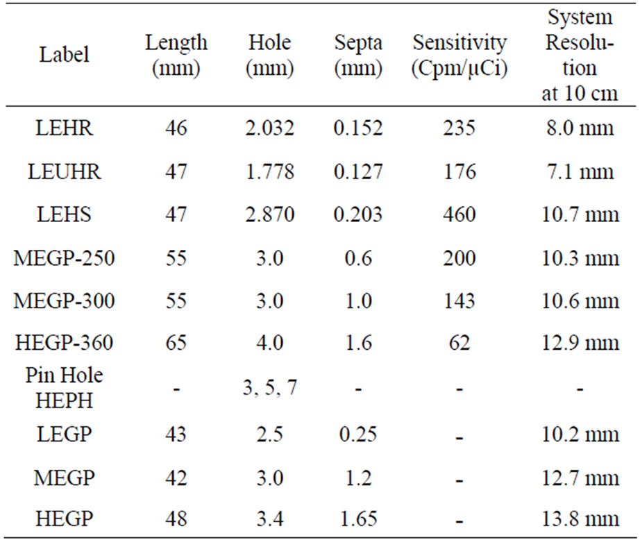
Table 1. Summary of collimator characteristics.

Figure 1. (A) AQCP mechanical section. Ball screw and reel and roll systems were used to position the point source in any desired point in space with a precision of 0.06 mm. (B) To get r related motor rotates the reel and the roll. (C) To get the Z and θ the ball screw system was used. Ball screw consists of a precise screw with a step of 1 mm and with a wide nut (with length of 4 cm). Another small nut was put under the wide nut. The θ parameter is adjusted by changing the position of the small nut and fixing it to the wide nut. When the small nut is open, the system can give different Z’s. So, in this system the Z and θ can be adjusted manually.
and Z2 = 13 cm as position 2 from the collimator and at each point of the collimators positions, the point source was imaged for a total of 50 k counts. For three HEPH collimators two images were taken at vertical distances of Z1 = 10 cm and Z2 = 13 cm as positions 1 and 2 and in horizontal center of collimators.
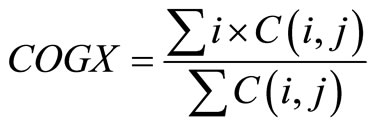
The data analysis of the two images as described in positions 1 and 2 is initiated with application of nine point smoothing kernel to reduce the random fluctuation in the data. The approximate X and Y coordinates (COGX and COGY) of each point source image is determined by calculating the centroids of each point source image from relations 1 and 2 [4,5]. COGX and COGY are, in fact, the estimated locations of point source image for each 140 points in image matrix.
 (1)
(1)
 (2)
(2)
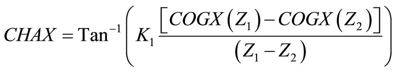
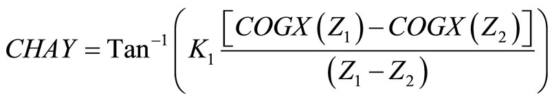
Here, C (i, j) is count in pixel (i, j). For each of the 140 points of the collimators the CHAX and CHAY were determined by relations 3 and 4 [2,4,5].
 (3)
(3)
 (4)
(4)
In relations 3 and 4: K1 = Pixel size (mm/pixel) and (Z1 – Z2) distance between two images in mm (for all measurements 30 ± 0.06 mm). The Root Mean Square (RMS) of CHA can be obtained by
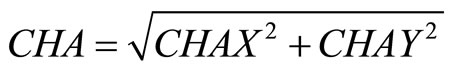 (5)
(5)
3. Results
Collimator Hole Angulation (CHA) Test: In the CHA measurement, the results of the 9 collimators of LEHR, LEHS, LEUHR, MEGP-250, MEGP-300 and HEPHs with hole diameters 3.5 and 7 cm of SMV camera and LEGP, MEGP and HEGP of GE Millennium MG were examined and the results obtained are shown in Figure 2 and Table 2. The images for LEHR CHA assessment were shown in Figure 3.
Repetition measurements for the three types of collimators including those obtained after re-running of the AQCP program gave an S.D. less than 0.1˚ for each point of collimator. CHA test was conducted within an average time of 30 - 35 min. The RMS (±S.D.) of CHA for 140 positions of LEHR, LEHS, LEUHR, MEGP with energy of 250, 300 and HEGP collimators of SMV camera were 0.290˚ (±0.207˚), 0.292˚ (±0.197˚), 0.208˚ (±0.184˚), 0.194˚ (±0.140˚), 0.181˚ (±0.130˚) and 0.177˚ (±0.120˚)
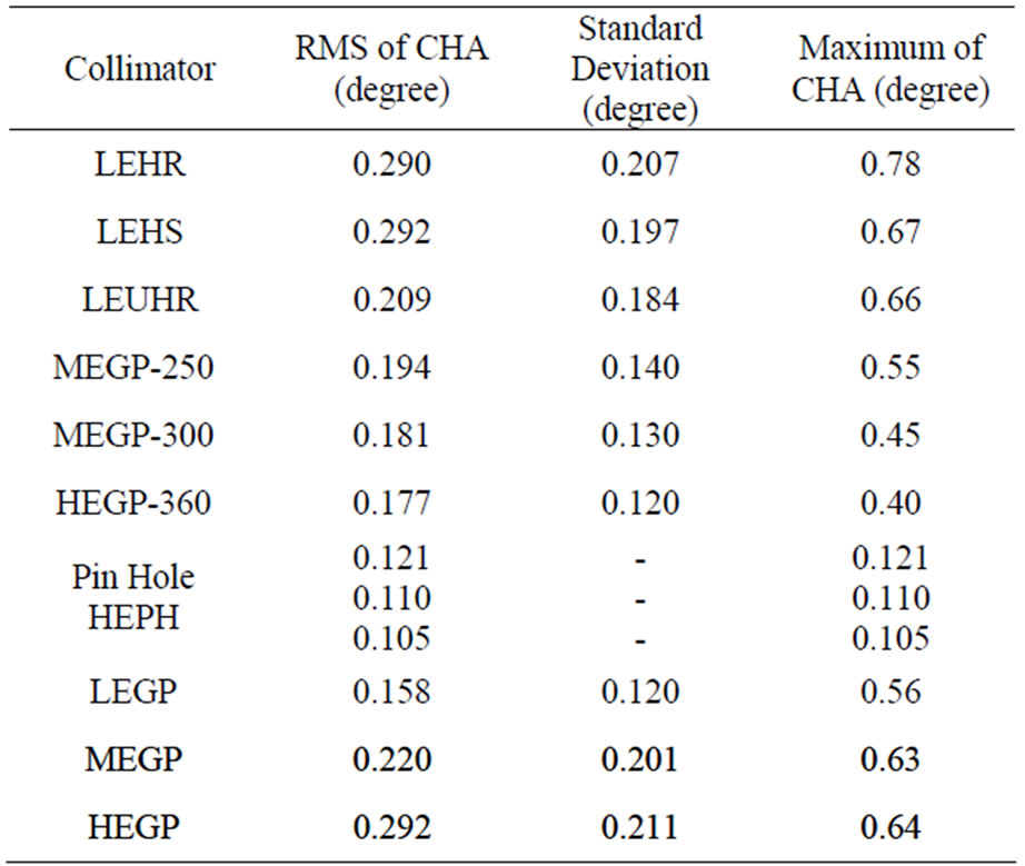
Table 2. CHA test results.

Figure 2. Statistical changes in CHA for LEHR, LEHS and LEUHR collimators of SMV camera and LEGP, MEGP and HEGP of GE Millennium MG.

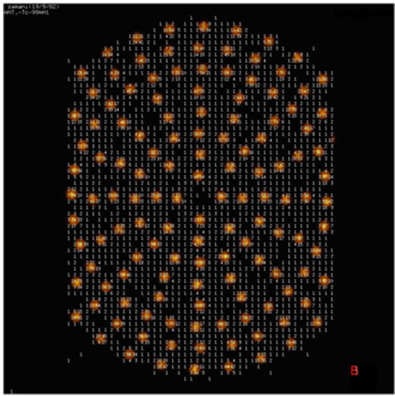
Figure 3. Two images were taken at 140 different points of LEHR collimator for measuring the CHA with AQCP method. The image A is taken in 10 cm distance and the image B in 13 cm distance from collimator surface.
respectively. The CHA of three HEPH collimators with hole diameter 3.5 and 7 are 0.121˚, 0.110˚ and 0.105˚ respectively. CHA test was conducted within an average time of 30 - 35 min. The RMS (±S.D.) of CHA for 140 positions of LEGP, MEGP and HEGP collimators of GE Millennium MG camera were 0.158˚ (±0.120˚), 0.220˚ (±0.201˚) and 0.292˚ (±0.211˚) respectively.
The Maximum of CHA for LEHR, LEHS, LEUHR, MEGP-250, MEGP-300 and HEGP-360 collimators of SMV camera were 0.78˚, 0.67˚, 0.66˚, 0.55˚, 0.45˚ and 0.40˚ respectively. The Maximum of CHA for LEGP, MEGP and HEGP collimators of Millennium MG camera were 0.56˚, 0.63˚ and 0.64˚ respectively.
In addition, it has been proved that the measured RMS of CHA for LEHR collimator with the distance variation from the collimator’s surface of ±1 mm has been varied only ±0.04 degree. The results for LEHR collimator indicate that a 1 mm change in (Z1 – Z2) ((Z1 – Z2) = (31 mm)) changes the RMS of CHA from 0.29˚ to 0.33˚ and –1 mm change in (Z1 – Z2) ((Z1 – Z2) = (29 mm)) changes the RMS of CHA from 0.29˚ to 0.25˚.
It should be mentioned that CHA is dependent on the variation of the distance of the two images. For precise measurement of CHA, the precise distance of the point source movement should be measured vertically away from collimator face.
4. Discussion
AQCP which is computerized and automated phantom with unique features in design and construction is capable of being adapted for diverse and various QC test measurements. AQCP produces spatial distribution of gamma rays to simulate QC phantom for acceptance and/or routine QC testing.
AQCP has some advantages compared to any other similar QC measurement methods which briefly include the following: reduction of radioactive material consumption, reduction of radiation exposure to the staff, reduction of QC test cost, implementation of QC program with one phantom, performing a uniform set of procedures, increasing the accuracy and precision of some QC tests, and automation of the measurements and evaluation processes.
5. Acknowledgements
The authors of the present paper should present their special thanks and appreciation to the administration and the staff of the Karaj Nuclear Medicine and Agricultural Research Center as well as Mr. Mehdi Zamani Zeinali for his cordial assistance.
REFERENCES
- R. E. Malmin, C. S. Peggy and W. R. Guth, “Collimator Angulation Error and Its Effect on SPECT,” Journal of Nuclear Medicine, Vol. 31, No. 5, 1990, 655-659.
- E. Busemann-Sokole, “Measurement of Collimator Hole Angulation and Camera Head Tilt for Slant and Parallel Hole Collimators Used in SPECT,” Journal of Nuclear Medicine, Vol. 28, No. 10, 1986, pp. 1592-1598.
- W. Chang, S. Q. Li, J. J. Williams, et al., “New Methods of Examining Gamma Camera Collimators,” Journal of Nuclear Medicine, Vol. 29, No. 5, 1988, pp. 674-683.
- American Association of Physicists in Medicine, “Rotating Scintillation Camera SPECT Acceptance Testing and Quality Control,” AAPM Report No. 22, College Park, 1987.
- International Atomic Energy Agency, “Quality Control of Nuclear Medicine Instruments,” IAEA TECDOC 602, Vienna, 1991.
- M. Eckholt and H. Bergmann, “Angulation Errors in Parallel-Hole and Fan Beam Collimators: Computer Controlled Quality Control and Acceptance Testing Procedure,” Journal of Nuclear Medicine, Vol. 41, No. 3, 2000 pp. 548-555.
- Y. Takahashi, K. Murase, H. Higashno, et al., “SPECT Imaging with Off-Set Detector System: Comparison of Sampling Angles 2, 4 and 6 Degrees,” Annals of Nuclear Medicine, Vol. 16, No. 5, 2002, pp. 343-347. doi:10.1007/BF02988623
- H. Hines, R. Kayayan, J. Colsher, et al., “Recommendations for Implementing SPECT Instrumentation Quality Control. Nuclear Medicine Section—National Electrical Manufacturers Association,” European Journal of Nuclear Medicine and Molecular Imaging, Vol. 26, No. 5, 1999, pp. 527-532. doi:10.1007/s002590050421
- G. B. Thomas, “Calculus and Analytic Geometry,” 4th Edition, Addison-Wesley Publishing Company, Boston, 1969.
- B. C. Kuo, “Automatic Control Systems,” 5th Edition, McGraw-Hill Companies, New York, 1987.
- Web Site of National Instruments Corporation. www.NI.com.
- H. Z. Zeinali, M. Ghiassi-Nejad and A. Mirzai, “Design an Adaptive Quality Control Phantom to optimize QC Test Methods,” The Open Medical Imaging Journal, Vol. 1, 2007, pp. 1-6.
- H. Z. Zeinali and A. Mirzai, “Design an Adaptive Quality Control Phantom to optimize Integral and Differential Uniformity, Collimator Hole angulation and Center of Rotation of SPECT,” The Journal of Instrumentation, Vol. 3, 2008, pp. 1-8. doi:10.2174/157340508784356743
- H. Z. Zeinali, M. Ghiassi-Nejad and A. Mirzai, “Design an Adaptive Quality Control Phantom to Optimize Uniformity, Collimator Hole Angulation and Center of Rotation of SPECT,” The Journal of Instrumentation, 2008. www.iop.org/EJ/jinst
NOTES
*Corresponding author.