Modern Mechanical Engineering
Vol.04 No.04(2014), Article ID:51874,14 pages
10.4236/mme.2014.44018
Experimental and FEM Modal Analysis of a Deployable-Retractable Wing
P. Jia1,2,3*, S. K. Lai4, W. Zhang3, C. W. Lim1,2
1Department of Architecture and Civil Engineering, City University of Hong Kong, Hong Kong, China
2Shenzhen Research Institute, City University of Hong Kong, Shenzhen, China
3College of Mechanical Engineering, Beijing University of Technology, Beijing, China
4Meinhardt (M & E) Ltd, Hong Kong, China
Email: *pengsir06010101@sina.com, skken.lai@gmail.com, sandyzhang0@yahoo.com, bccwlim@cityu.edu.hk
Copyright © 2014 by authors and Scientific Research Publishing Inc.
This work is licensed under the Creative Commons Attribution International License (CC BY).
http://creativecommons.org/licenses/by/4.0/


Received 12 September 2014; revised 16 October 2014; accepted 2 November 2014
ABSTRACT
The aim of this paper is to conduct experimental modal analysis and numerical simulation to verify the structural characteristics of a deployable-retractable wing for aircraft and spacecraft. A modal impact test was conducted in order to determine the free vibration characteristics. Natural frequencies and vibration mode shapes were obtained via measurement in LMS Test. Lab. The frequency response functions were identified and computed by force and acceleration signals, and then mode shapes of this morphing wing structure were subsequently identified by PolyMAX modal parameter estimation method. FEM modal analysis was also implemented and its numerical results convincingly presented the mode shape and natural frequency characteristics were in good agreement with those obtained from experimental modal analysis. Experimental study in this paper focuses on the transverse response of morphing wing as its moveable part is deploying or retreating. Vibration response to different rotation speeds have been collected, managed and analyzed through the use of comparison methodology with each other. Evident phenomena have been discovered including the resonance on which most analysis is focused because of its potential use to generate large amplitude vibration of specific frequency or to avoid such resonant frequencies from a wide spectrum of response. Manufactured deployable-retractable wings are studied in stage of experimental modal analysis, in which some nonlinear vibration resulted should be particularly noted because such wing structure displays a low resonant frequency which is always optimal to be avoided for structural safety and stability.
Keywords:
Deployable-Retractable Wing, Experimental Modal Analysis, FEM, Mode Shapes, Natural Frequency, LMS Test. Lab

1. Introduction
In recent years, there has been considerable research focusing on aircraft morphing wing [1] due to its high efficiency during manoeuvre or flight operations. This is because aircrafts with morphing structures are able to change its configuration in order to adapt to varying flight conditions and to maximize its performance. This morphing wing concept can be classified into three major types: planform alternation, out-of-plane transformation, and airfoil adjustment. For the planform alternation category, the wing area could be adjusted such that the wing sweep is continuously altered to suit the best operation conditions. For the out-of-plane transformation category, the wing chord and span-wise camber can be suitably changed such that the twisted wing could be controlled. For airfoil adjustment, the wing airfoil cross-sectional profile could be lively adjusted while the wing fixture remains unaltered.
To exploit these new concepts, the Defense Advanced Research Projects Agency (DARPA) [2] , began in 2003 a program on Morphing Aircraft Structures (MAS) and its main objective was to develop wing structures with the ability to change wing shape and geometry substantially in order to accommodate the very different performance demands of varying missions and manoveuvre conditions. By introducing variable stiffness components [3] , a promising solution was offered for the inherent contradiction between high stiffness and reversible deformation capacity posed by morphing. A wide range of studies has been published which addressed the variable structural stiffness from a pure morphing perspective point of view. The studies can be grouped into four broad approaches: material engineering, active mechanical design, semi-active techniques and elastic structural behavior manipulation. A “Morphing Laminar Wing” (MLW) [4] concept has been introduced and it has a flexible skin and actuators connected by a transmission system. It is capable of inducing friction drag reduction by extending the laminar flow over an active wing extrados and it has been proven effective for subsonic aerodynamic conditions. An optimal design for a MLW active structure has been developed. Reich and Sanders [5] listed the major challenges of a morphing wing design that included the requirement for distributed high-power density actuation, structural mechanization, flexible skins, and efficient control regulations.
Following the concept of a morphing wing as described above, this paper focuses on a class of aircraft wing which are able to deploy and to retreat continuously and these wings are called the deployable-retractable wings. The wing span is adjustable and its main components include a fixed wing, a moveable wing, a base part and a screw vice. The symmetric span morphing wings are good at reducing the vortex induced drag, extending endurance, and reducing the take-off field length and landing distance. Wind tunnel tests [6] showed that a variable span wing was able to maintain sufficiently low drag throughout a range of lift coefficients. On the other hand, telescopic structures have been extensively applied to achieve a dramatic length of the wing structure and this telescopic mechanism could smoothly be operated at a wide range of distance with different rotation speed.
In general, there are two distinct approaches for modal analysis, the experimental modal analysis [7] and the numerical simulation modal analysis. When a structure is subjected to an input force, the most common data that can be obtained is the frequency response function (FRF) that carries the frequency and mode shape characteristics. Experimental modal analysis is a typical method which has been widely used in structural engineering for determining structural modal parameters, such as natural frequencies, mode shapes, etc. Bart Peeters et al. [8] applied a multisine excitation to a full-scale F-16 aircraft in order to obtain an improved FRF and to assess the vibration characteristics. By ground vibration test, an onera-dlr [9] specialized team conducted an experimental modal analysis on a new design for Airbus, a composite Airbus A350 XWB. A modal experimental analysis was performed on an Unmanned Aircraft System [10] and the effects of wing pods on the structural characteristics of the aircraft were investigated. In another study, highly flexible morphing wings were studied using experimental identification of structures [11] . Vibration tests were performed on a joined wing structure for a range of static load at different vibration levels. An add-on tool which was able to extend the traditional modal testing procedures to nonlinear applications was also presented in this analysis. Lynx Mk7 (XZ649), an experimental modal analysis was applied to estimate the modal parameters [12] , where a ground vibration test was performed and the behavior of both frequency- and time-domain-based operational modal analysis techniques were applied for the modal parameter estimates. The results were estimated using an Experimental Modal Analysis approach based on the experimental frequency response functions, and the Operational Modal Analysis method was applied directly to the output response functions. An experimental test with analysis on an F-16 aircraft [13] using modal analysis was presented. The analysis was advantageous because the relationship between the degree of the test data and the cloud points was not needed.
The structure of this deploying-and-retreating wing will be easily changed as the moveable wing deploys or retreats and those introduced changes in turn influence the structural vibration response [14] , for most applications especially resonant frequencies are easy to measure and to be used for further analysis [15] [16] . This paper is to conduct vibration test on a deploying-and-retreating wing to detect how difference rotation speed influence this telescopic morphing wing structure. The main content of this paper is in two areas, an experimental modal analysis using LMS Test. Lab and a numerical finite element (FE) modal simulation using ANSYS. A comparison between the FE simulation and the measured test data will be presented to justify the agreement between the two different approaches.
2. Modal Impact Experiment Setup and Procedure
2.1. Deployable-Retractable Wing
A three-dimensional geometric model and the Cartesian coordinate system are shown in Figure 1. This geometry of this deployable-retractable wing is constructed in Pro/ENGINEER by creating each individual part and then assembling them together. It is observed that the main structure resembles a typical cantilever beam.
The schematic diagram of the experimental apparatus used to identify the modal parameter is illustrated in Figure 2 and this structure has been fabricated and located in a laboratory. Subsequent experimental tests were conducted to obtain further insights into this telescopic structure and to verify the feasibility of this new concept of morphing wing. The frame is made of aluminum alloy and its wing span is adjustable by controlling the inner movable wing which is located in the middle of the fixed, but bigger outer wing. The structural characteristics of the entire wing can be altered by changing the location of the movable wing. The state of motion of this moveable wing is controlled by a specialized control system consisting of STC89C52 SCM, an AC servo motor and two margin micro-switches. The variable speed and directions are realized by this control system, at the same time, the screw vice and bevel gears translate the rotation of servo gear to linear motion of the movable wing.
2.2. Testing Setup and Procedure
In laboratory tests, an ideal impact to be excited on a structure is an instantaneous impulse with an infinitely small duration. The impact causes constant amplitude in frequency domain and it results in a combination of all modes of vibration being excited with an equal amount of energy.

Figure 1. Geometric figure of deployable-retractable wing.

Figure 2. Experimental setup of the deployable-retractable wing.
In this study, a hammer impact test is designed to produce a test as described above. However, in reality a hammer strike cannot last for an infinitely small duration, instead the strike lasts for a definite known period of contact time. The contact time duration directly influences the frequency response of the force and a longer contact time induces a smaller range of bandwidth. A load cell is attached to the end of the hammer to record the force. A hammer impact test is ideal for small light weight structures. As the size of structure increases, other undesirable issues may occur due to a poor signal-to-noise ratio. This is common for large civil engineering structures.
The experimental modal analysis is conducted in two major steps, the modal impact test and the modal analysis. The modal analysis aims to measure the frequency response functions, response phases and coherence of structure. To conduct a modal impact test, the experiment setup requires B & K acceleration sensors, an impact hammer with various heads, and a SCADAS Mobile Data Acquisition System with a total of 40 channels. The data analysis software used in this study is LMS Test. Lab. Another 3-D geometry of this deployable-retractable morphing wing is created using Test. Lab and it is illustrated in Figure 3.
A total of seven acceleration sensors are installed at asymmetric locations as shown in Figure 4. The acceleration response at these points are recorded via ICP B & K sensors, with an average 0.18 C/(ms2) sensitivity. The rubber and nylon hammers are used to produce an impact on this wing structure separately.
To setup the channel, the impact hammer and acceleration sensors are respectively connected to channels of LMS SCADAS, which has 40 channels in total. More importantly, directions of the hammer and acceleration sensors must be correctly adjusted to match the axis of the geometric model in order to present better animations. In general, fine modal data can be obtained if sufficiently many impact points are planted. The 3D geometric points represent two different kinds of channels, one of which is connected to B & K acceleration sensors shown in Figure 4 and the other ones to the impact points. In this study, seven acceleration sensors are used to acquire the output signal and more than thirty impact points are located on the structure. The acceleration sensors are planted in an asymmetric format with respect to their measured positions. This is because highly regular and symmetric arrangement might result in bad response data, as what has been verified through many experimental experiences. After completing the test setup, the hammer impact test can be conducted on the deployable- retractable wing. The B & K acceleration sensors are adhered to the wing structure. While testing, the impact hammer hit the wing five times so that sufficient data can be collected for calculating an average value. The procedure is repeated for other impact points.
3. Measurement and Analysis
3.1. Coherent Coefficient
The modal coherent coefficient is one critical parameter to evaluate whether an experimental modal analysis is reliable because it reflects how different experimental measurements agree with each other. In order to ensure

Figure 3. Wing geometry in LMS Test. Lab.

Figure 4. Acceleration locations used in EMA.
reliability of measured data, the coherent coefficient should be limited to between 0.8 and 1.0. A typical case of the coherent coefficient plot in this study is shown in Figure 5. It shows that the measurement of modal impact tests in this study is considerably reliable for frequencies below 1000 Hz approximately. Beyond 1000 Hz, it drops significantly below 0.8 and such measurements are unreliable to a certain degree.
3.2. PolyMAX Method
The PolyMAX method is a mathematical approach related to the least-square complex frequency-domain (LSCF) estimation method. The LSCF method identifies a so-called common-denominator model and it was introduced to find the initial values for the iterative maximum likelihood method [17] . The most important advantage of the LSCF estimator over the widely applied parameter estimation techniques [18] is that very clear stabilization diagrams can be obtained. In some previous studies, it was identified that the common-denominator model closely fitted the measured FRF data [19] [20] . To improve its mathematical analysis, a polyreference version of the LSCF method, called “PolyMAX” [21] [22] , was developed. Figure 6 presents the stabilization diagram obtained by using PolyMAX, where each mode of the deployable-retractable wing is extracted. In the extracted modes in this figure, there are more “s” values at the peaks of the response curve and these “s” points are the stable points of frequency and damping ratio. The peaks on the FRF plots of each point correspond to the natural frequencies and the corresponding mode shapes identified using PolyMAX can be further used for animation.

Figure 5. Coherent coefficient plot.

Figure 6. Stabilization diagram obtained by using LMS PolyMAX solver.
Experimental modal analysis of the wing as a telescopic structure is conducted with an impact hammer. The natural frequencies are presented in Table 1. Because the morphing wing structure is adjustable corresponding to the state of movable wings, it is necessary to repeat the procedure to obtain more accurate data. Three cases of modal experiments are completed and a total number of . FRFs are obtained and used for the identification of the modal parameters. The first case corresponds to a non-extended inner movable wing (State 1),

Table 1. Natural frequencies and mode shape descriptions estimated with EMA.
the second case (State 2) corresponds to state that the remote edge of movable wing is 400 mm away from the fixed wings, and the third case (State 3) is for a distance of 600 mm away from the fixed wing. In this paper, 15 mode shapes in the frequency band 0 - 420 Hz are identified using the LMS PolyMAX solver. These modes represent the rigid bending modes in the z-direction and the torsion modes with respect to the longitudinal axis (x-direction). The specific telescopic wing structure can be approximately treated as a cantilever plate vibrating in the x- and y-directions. For State 1, the first vibration mode of this morphing wing is a typical bending mode as shown in Table 2 with a natural frequency of approximately 8.3 Hz. It implies that vibration resonance may be relatively easy to be excited for this deployable-retractable wing. Consequently, for an aircraft with a morphing wing at this state, a low frequency excitation around 8 Hz must be avoided to ensure flight safety. From Table 2, it is also clear that the second vibration mode corresponds to the first torsion mode about the x-axis at frequency 25.3 Hz; the third vibration mode illustrates a second bending mode in z-direction at the frequency of 75.5 Hz; the fourth vibration mode represents the second torsion mode at frequency 138.9 Hz; and the fifth vibration mode is the third bending mode at frequency 372.4 Hz. A decrease in natural frequency is observed as the corresponding deploying length increases. It is consistent with the fact that the stiffness of a longer structure is lower.
3.3. Comparison and Convergence Analysis
In this section, a comprehensive comparison study is presented and mode shapes identified by experimental modal analysis are directly compared with FEM simulation as shown in Table 2. The numerical natural frequencies and vibration mode shapes are simulated using ANSYS. The material parameters are listed as follows, Young’s modulus , Poisson’s ratio
  and Density
 . The FE model is meshed with SOLID 45 and a total of more than 370,000 elements are obtained. It is necessary to create joint blocks in the mesh model because the moveable wing is attached to the fixed wing as a structural entity. To simplify the model, the screw and bearing are ignored in order to avoid unnecessary complexity in this study. The wing skin is also ignored in both simulation and experiment. In numerical analysis, the Block Lanczos Method is applied to obtain the numerical modal results. The first five vibration mode shapes are illustrated in Table 2.
It can be summarized from Table 2 that both the tested and simulated vibration modes are similar and they are the first bending modes. Similar conclusion can also be observed for other bending vibration modes and torsion vibration modes.
Excellent agreement is observed in Figure 7 by comparing the FEM natural frequencies and experiment. However, there are only five vibration modes identified in this experiment modal analysis and the number is smaller than that determined in FEM analysis. This is mainly due to the limitation of impact direction constraints in the experiments. For example, the mode shapes in all directions are simulated in FEM analysis, including the bending modes and torsion modes. However in the experimental modal analysis, only the vibration response with respect to the z-axis is targeted while the response with respect to the other two axes is ignored. Consequently the total number of experimental mode shapes detected is fewer than that of FE simulation. In addition, all measured data mainly focus in the transverse directions but FE simulation does not have such constraint. Comparison of The FEM numerical solution and experiment for natural frequency is presented in Figure 7.
The mesh generation in different element sizes mesh numerical convergence is discussed here. Mesh size ef-
Table 2. Concise presentations of mode shapes obtained in experiment and simulation.
fect is considered as one of the key factors for numerical accuracy. The initial coarse FE meshes used in the simulation is shown in Figure 8 and a much finer meshed model is presented in Figure 9. The initial smart

Figure 7. Comparison of natural frequency at typical mode shapes.

Figure 8. Coarse mesh smart-size = 10 (no black background).
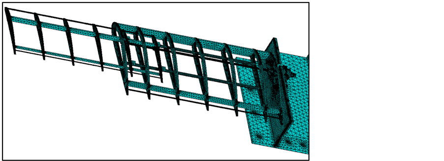
Figure 9. Fine free mesh smart-size = 6 (no black background).
meshing size is 10 and 20,774 meshed elements are created. For each simulation, the parameters such as element type, material properties and solving conditions remain unchanged. By decreasing the element size, good numerical convergence can be obtained in modal analysis. The numerical convergent solutions are derived and presented in Figure 10. It is observed that decreasing the mesh element smart-size (i.e. increasing the number of elements) convincingly increases numerical accuracy. It is also obvious that the vibration frequencies converge downwards and the lower modes converge at a faster rate than the higher modes.
4. Vibration Test
Testing System
The complete experimental system is divided into two main components, including hardware of mechanical structure and the acquisition-and-analyzing system. Three measured points are numbered to identify the amplitudes of transverse vibration data, as presented in Figure 11. In order to detect the response signal, three acceleration sensors have been planted at corresponding locations, two of them are attached to the fixed wing surface, while the last one is fixed at the end of moveable wing. Figure 11 clearly displays the location of sensors: Sensor No.1 locates at the middle of the fixed wing, Sensor No. 2 at the most remote point of the fixed wing and Sensor No.3 is attached on the wing surface where the last, bigger rib is located.
In this section, series of vibration tests have been performed in order to characterize distinguished resonance on this specific telescopic wing structure. This means changes in the rotation speed of motor are the basic conditions to distinguish such control experimental groups from each other, and vibration data have been collected as this speed changes from 350 r/min to 1450 r/min. Considering the integrity of wing’s working, sufficient similar testing groups have been performed in a total number of 28 including both the deploying and retreating process. In each group, transverse vibration signal response, excited by corresponding rotation speed of motor, is acquired by the SCADAS, transferred and stored by LMS Test. Lab software completely in time-domain. After data processing, three calculated FRFs are obtained and presented in both the peak values of these curves and its resonance frequency. Consider the time-domain transverse vibration signal, the maximum value of displacement is easily discovered at the time when resonance occurs. After comparing the measured data, the maximum response in deflection is obtained. Three sensor channels acquired maximum transverse vibration response and it is noted that none of them are found in deploying process. It implies that vibration at resonance is very likely to be excited when the moveable wing retracts to the fixed wing chamber, rather than during the deploying process. Three groups of typical response are illustrated in Figures 12-14 in which the maximum transverse vibration response is detected at the measured point.

Figure 10. Convergence of natural frequencies.
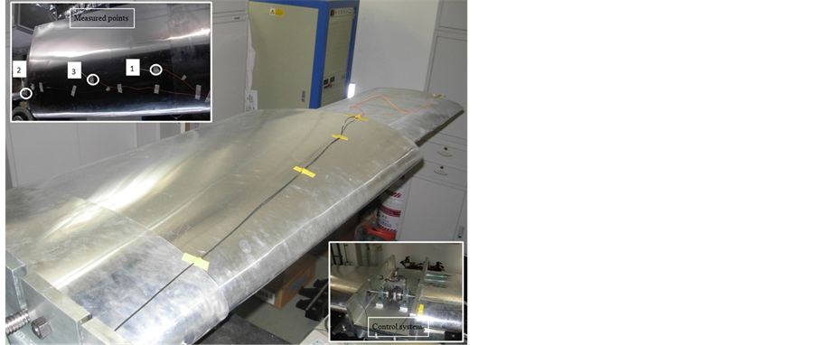
Figure 11. Experiment equipments used in vibration test.

Figure 12. Transverse vibration response and frequency response curve of point 1 at rotation speed 700 r/min with a maximum at 10.28 mm (retreating).
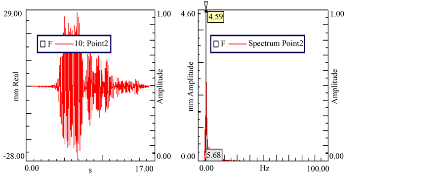
Figure 13. Transverse vibration response and frequency response curve of point 2 at rotation speed 650 r/min with a maximum at 28.07 mm (retreating).

Figure 14. Transverse vibration response and frequency response curve of point 2 at rotation speed 650 r/min with a maximum at 16.42 mm (retreating).
These significant values and identified information are summarized in Table 3 and Table 4, where several additional parameters are reported to reveal how this telescopic wing structure is influenced by different rotation speeds.
The experiment curve generated by the sliding velocity of moveable wing with respect to the maximum transverse vibration is shown in Figure 15. The curves correspond to the channels and the sliding velocity is converted by the wing deploying velocity. This figure shows that the deployable-retractable wing is influenced by various rotation speeds and the transverse response signal varies with parametric excitation. As shown in the figure, the peak vibration amplitude increases first and then it decreases as the moveable wing deploys faster. In particular, when the motor rotates at a speed of 750 r/min, the respective retreating velocity increases to approximately 60 mm/s, and the peak value of each channel occurred. In is concluded that forced vibration resonance has been excited in this morphing wing because of the impulse signal generated by motor rotation. In addition, the measured point No. 3 has larger peak response signal than the other two in each test run. Hence, the common conclusion that a longer structure results in more severe vibration is reached.
5. Conclusions
This paper aims to use a combination of experiment methodology and FEM modal analysis to study an especially designed deployable-retractable morphing wing. The free vibration of this morphing wing has been investigated by a hammer impact test and the measured data are compared with FEM solutions. In order to obtain original insights into the vibration mode shapes and natural frequencies of this telescopic structure, a good comparison result between the numerical simulation and experiment for the first five vibration modes has been completed.
Three distinct states have been considered in this paper. The first one is a non-extended movable wing and the other two correspond to two different extended states of moveable wing. The fundamental natural frequency is approximately 8 Hz and it is rather low. Hence, it is concluded here that any random impulse or unexpected excitation from the surrounding environment could easily excite a resonance at this state. It is probably and potentially very harmful to the morphing wing structure and therefore precaution should be taken to avoid resonance at this state.
It is recorded that an increasingly extended movable wing has lower natural frequencies. This experimental observation is consistent with knowledge in structural dynamics that a longer structure has lower natural frequencies. Different dynamic vibration characteristics for a movable wing at different extended positions are also recorded in this paper.
Fourteen cases at different motor rotation speeds are examined. The speed ranges from 350 r/min to 1450 r/min in 100 r/min and 50 r/min increments while the relevant sliding speed changes from 10 mm/s to 125 mm/s. The vibration amplitude at different rotation speeds and the corresponding vibration responses have been reported in this paper. The experiment and FEM simulation results agree well and the data will be of reference values in the future. It is recommended here that further research on the effects of varying angle of attack, varia-
Table 3. Vibration response for retreating moveable wing.
Table 4. Vibration response for deploying moveable wing.

Figure 15. Experimental curves of retreating velocity and maximum vibration.
ble airfoil profile and pretwisted airfoils will be conducted.
Acknowledgements
The authors gratefully acknowledge the support of the National Natural Science Foundation of China (NNSFC) through grant Nos. 11290152, 11072008 and 10732020, and the Funding Project for Academic Human Resources Development in Institutions of Higher Learning under the Jurisdiction of Beijing Municipality (PHRIHLB), and National Natural Science Foundation of China through a research grant awarded to the Shenzhen Research Institute, City University of Hong Kong (Project No. 11272271).
References
- Zhang, W., Sun, L., Yang, X.D. and Jia, P. (2013) Nonlinear Dynamic Behaviors of a Deploying-and-Retreating Wing with Varying Velocity. Journal of Sound and Vibration, 332, 6785-6797. http://dx.doi.org/10.1016/j.jsv.2013.08.006
- Zhao, Y.H. and Hu, H.Y. (2013) Prediction of Transient Responses of a Folding Wing during the Morphing Process. Aerospace Science and Technology, 24, 89-94. http://dx.doi.org/10.1016/j.ast.2011.09.001
- Kuder, I.K., Arrieta, A.F., Raither, W.E. and Ermanni, P. (2013) Variable Stiffness Material and Structural Concepts for Morphing Applications. Progress in Aerospace Sciences, 63, 33-55. http://dx.doi.org/10.1016/j.paerosci.2013.07.001
- Coutu, D., Brailovski, V. and Terriault, P. (2010) Optimized Design of an Active Extrados Structure for an Experimental Morphing Laminar Wing. Aerospace Science and Technology, 14, 451-458. http://dx.doi.org/10.1016/j.ast.2010.01.009
- Reich, G. and Sanders, B. (2007) Introduction to Morphing Aircraft Research. Journal of Aircraft, 44, 1059. http://dx.doi.org/10.2514/1.28287
- Sofla, A.Y.N., Meguid, S.A., Tan, K.T. and Yeo, W.K. (2010) Shape Morphing of Aircraft Wing: Status and Challenges. Material and Design, 31, 1284-1292. http://dx.doi.org/10.1016/j.matdes.2009.09.011
- Peeters, M., Kerschen, G. and Golinval, J.C. (2011) Modal Testing of Nonlinear Vibrating Structures Based on Nonlinear Normal Modes: Experimental Demonstration. Mechanical System and Signal Processing, 25, 1227-1247. http://dx.doi.org/10.1016/j.ymssp.2010.11.006
- Peeters, B., Carrella, A., Lau, J., Gattp, M. and Coppotelli, G. (2011) Advanced Shaker Excitation Signals for Aerospace Testing. Advanced Aerospace Applications, 1, 229-241.
- Lubrina, P., Giclais, S., Stephan, C., Boeswald, M., Govers, Y. and Botargues, N. (2014) AIRBUS A350 XWB GVT: State-of-the-Art Techniques to Perform a Faster and Better GVT Campaign. Conference Proceedings of the Society for Experimental Mechanics Series, Topics in Modal Analysis II, Vol. 8, 243-256.
- Lemler, K.J. and Semke, W.H. (2013) Application of Modal Testing and Analysis Techniques on a sUAV. Conference Proceedings of the Society for Experimental Mechanics Series, Special Topics in Structural Dynamics, Vol. 6, 47-57.
- Londono, J.M. and Cooper, J.E. (2014) Experimental Identification of a System Containing Geometric Nonlinearities. Proceedings of the 32nd IMAC, A Conference and Exposition on Structural Dynamics, Conference Proceedings of the Society or Experimental Mechanics Series, 7, 253-260.
- Ameri, N., Grappasonni, C., Coppotelli, G. and Ewins, D.J. (2013) Ground Vibration Tests of a Helicopter Structure Using OMA Techniques. Mechanical Systems and Signal Processing, 35, 35-51. http://dx.doi.org/10.1016/j.ymssp.2012.09.013
- Lau, J., Peeters, B., Debille, J., Guzek, Q., Flynn, W., Lange, D.S. and Kahlmann, T. (2011) Ground Vibration Testing Master Class: Modern Testing and Analysis Concepts Applied to an F-16 Aircraft. Advanced Aerospace Applications, Conference Proceedings of the Society for Experimental Mechanics Series, 1, 221-228.
- Trendafilova, I., Cartmell, M.P. and Ostachowicz, W. (2008) Vibration-Based Damage Detection in an Aircraft Wing Scaled Model Using Principal Component Analysis and Pattern Recognition. Journal of Sound and Vibration, 313, 560-566. http://dx.doi.org/10.1016/j.jsv.2007.12.008
- Doebling, S.W., Farrar, C.R. and Prime, M.B. (1998) A Summary Review of Vibration-Based Damage Identification Methods. The Shock and Vibration Digest, 30, 91-105.
- Hu, N., Wang, X., Fukunaga, H., Yao, Z.H., Zhang, H.X. and Wu, Z.S. (2001) Damage Assessment of Structures Using Modal Test Data. International Journal of Solids and Structures, 38, 3111-3126. http://dx.doi.org/10.1016/S0020-7683(00)00292-4
- Peeters, B., Baets, P.D., Mosenich, L., Vecchio, A., Auweraer, H.V. and Lambert, F. (2005) Ground Vibration Testing in the Aeroelastic Design and Certification of a Small Composite Aircraft. 46th AIAA/ASME/ASCE/AHS/ASC Structures, Structural Dynamics and Materials Conference, Austin, 18-21 April 2005, 5370-5383.
- EI-Kafafy, M., Guillaume, P. and Peeters, B. (2013) Modal Parameter Estimation by Combining Stochastic and Deterministic Frequency-Domain Approaches. Mechanical Systems and Signal Processing, 35, 52-68. http://dx.doi.org/10.1016/j.ymssp.2012.08.025
- Van Der Auweraer, H., Guillaume, P., Verboven, P. and Vanlandutt, S. (2001) Application of a Fast-Stabilization Frequency Domain Parameter Estimation Method. ASME Journal of Dynamic Systems, Measurement, and Control, 123, 651-658.
- Heylen, W., Lammens, S. and Sas, P. (1997) Modal Analysis Theory and Testing. K. U. Leuven, Belgium.
- Mala, N.M.M. and Silva, J.M.M. (1997) Theoretical and Experimental Modal Analysis. Research Studies Press, Taunton.
- Pierro, E., Muchi, E., Soria, L. and Vecchio, A. (2009) On the Vibro-Acoustical Operational Modal Analysis of a Helicopter Cabin. Mechanical Systems and Signal Processing, 23, 1205-1217. http://dx.doi.org/10.1016/j.ymssp.2008.10.009
NOTES

*Corresponding author.