Modern Mechanical Engineering
Vol.4 No.3(2014), Article
ID:49343,11
pages
DOI:10.4236/mme.2014.43013
The Effect of the Variation of the Downstream Region Distance and Butterfly Valve Angle on Flow Characteristics in a 90 Degree Bended Elbow
Se Youl Won, Jae Gon Lee, Jun Seok Yang
Central Research Institute, Korea Hydro & Nuclear Power Co., Ltd., Daejeon, Korea
Email: w1310@khnp.co.kr
Copyright © 2014 by authors and Scientific Research Publishing Inc.
This work is licensed under the Creative Commons Attribution International License (CC BY).
http://creativecommons.org/licenses/by/4.0/


Received 23 June 2014; revised 24 July 2014; accepted 4 August 2014
ABSTRACT
This study presents the numerical evaluation about the impact of flow disturbance near the intrados and extrados regions of the 90 degree bended elbow using CFX for several practical cases where the 90 degree bended upward elbow is located in a proximity to the butterfly valve and the butterfly valve open angle is changed. For the change of a butterfly valve open angle from 60% to 100% and the increase of the distance between a valve and a 90 degree bended elbow, the effect of FAC (Flow-Accelerated Corrosion) in the 90 degree bended elbow may be neglected because the value and distribution of the velocity and shear stress is rapidly decreased comparing with the present status installed in an industry, and the data of 100% valve open (Case 3) and L/D ≈ 5 (Case 4) are very good agreement comparing with the reference data, L/D ≈ 8 (Case 2). The reasons are that flow already maintains a fully developed condition and a steady state in spite of less distance than the reference case, L/D = 8. Therefore, smooth flow fields have approached at a 90 degree bended elbow. Then, the effect of shear stress and vortex is hardly investigated around the intrados area of 90 degree bended elbow.
Keywords:Flow Disturbance, Shear Stress, 90 Degree Bended Elbow, Butterfly Valve, FAC

1. Introduction
Butterfly valves are widely used in industrial piping components. Addy et al., Eom, and Morris and Dutton show that butterfly valves are used for flow control in large diameter pipes because of their lightweight, simple structure and the rapidity of manipulation [1] -[3] . The principal advantages of this type of valve are their simplicity, their low cost, their speed of closing and the weak pressure drop which they produce when they are completely open. Park and Lee report that the phenomena of flow disturbance such as a pair of counter-rotating separation and recirculation zones are strongly depended on the disk open angle [4] . Barton presents that the wear scar such as pinhole may be swept round to the inside, downstream surface of the elbow for liquid flows [5] . EPRI, and Danbon and Sollice report that flow disturbing components such as elbows, orifice plates and tees are generally recommended to be located in a distance of 8 diameters (L/D ≈ 8) from the downstream of butterfly valves to decrease the effect of flow disturbance [6] [7] . However, one would encounter cases where other piping components are frequently installed in a close proximity due to the space restriction. In these cases, the numerical simulation will be useful to evaluate the impact of flow disturbances.
In this study, we have examined one practical case encountered where the elbow is located in a close proximity to the butterfly valve. Through the numerical analysis, therefore, this paper provide an optimized installation condition of region distance and valve angle for preventing piping thinning and pinhole by the variation of rapid flow disturbance and the shear stress effect such as vortex shedding near the intrados and extrados region of elbow due to the close proximity of elbow and butterfly valve.
2. Valve and Piping Line Arrangement
Figure 1 shows that the piping system consists of 50.8 cm diameter pipe (ID = 48.6 cm), a 90 degree elbow, flanges, an orifice plate and a butterfly valve. The distribution of the flow velocity and shear stress are analyzed to understand the effect of flow disturbance on the piping wall of a 90 degree bended elbow. The present study is conducted using four difference cases. Case 1 is the current arrangement: 60% valve open angle and L/D ≈ 1for the present operating case. Case 2 is the reference configuration, L/D ≈ 8, recommended with 60% valve open angle. This will be used as reference data for evaluation presented by EPRI [6] , and Danbon and Sollice [7] . Case 3 is 100% valve open angle and L/D ≈ 1. Case 4 is 60% valve open angle and L/D ≈ 5. Summary of the numerically analyzed test apparatus applied in this study is given in Table1
3. Numerical Approach and Procedures
The CFX code, version 10 [8] , is employed for the numerical predictions. ANSYS ICEM CFD 10.0 is used for the generation of the computational grid. A uniform velocity profile is employed at the inlet. Reynolds number based on channel height (ReH) is fixed at 1.9 × 10⁶, which corresponds to a spatially averaged channel inlet velocity is 3.72 m/s. Working fluid density and viscosity is 1025 kg/m3 and 9.71 × 10⁻⁴ kg/m-s, respectively. All computations are performed using turbulent flow. The energy equation is solved neglecting any radiation effects. Also, the time-averaged flow field is assumed to be at a steady state.
3.1. Computational Grid
Figure 2 shows the schematic diagram of the portion of computational grid for the butterfly valve and a 90 degree bended elbow section. The grids consist of 430,000 tetrahedral elements aligned with the flow direction to reduce the numerical dissipation errors, and thus improve the quality of the numerical prediction. Also, prism mesh is chosen for the near-wall surface region to resolve the development of the boundary layers better.
3.2. Computational Parameters and Closure Model
The RNG (Renormalization Group) k-ε model is employed as the turbulence model, because of its improved statics method to cover various length scales. Also, this RNG k-ε model is applied because the predictive capabilities and the convergence characteristics are much better than those of the standard k-ε model for a curved flow path such as an elbow, specially.
3.3. Solution Convergence
Each computational iteration is solved implicitly. The convergence of the computational solution is determined based on scaled residuals for the continuity and energy equations, and for many of the predicted variables. The
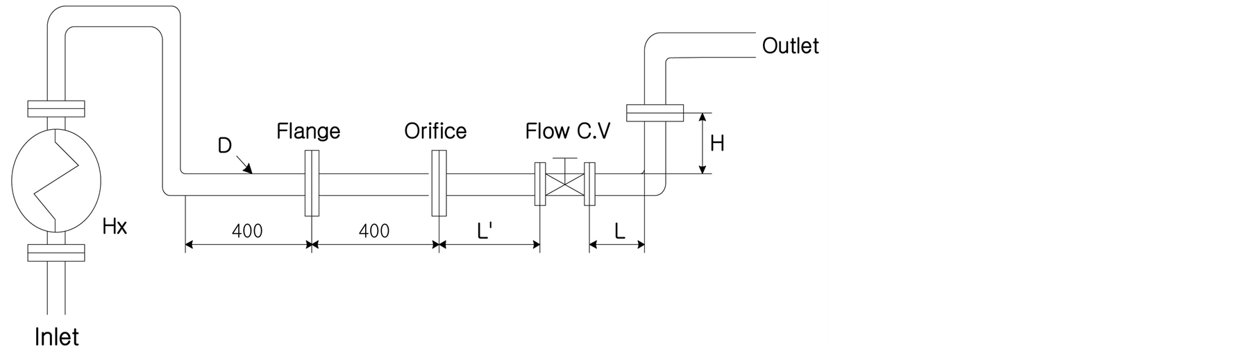
Figure 1. Schematic diagram of the test apparatus including piping system.
 (a) (b)
Figure 2. The schematic diagram of the portion of computational grid employed with (a) an orifice plate, (b) a butterfly valve and a 90 degree bended elbow.

Table 1. Summary of test conditions applied.
total residual for a given variable is based on the imbalance in an equation for conservation of that variable summed over all computational cells. The settings for the scaled residuals for solution convergence are set to 10−3 for nearly all computed residuals. The solution is considered to be converged when all of the scaled residuals are less than or equal to these default settings.
4. Results and Discussion
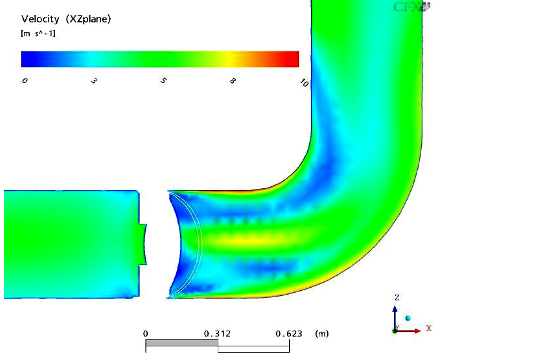
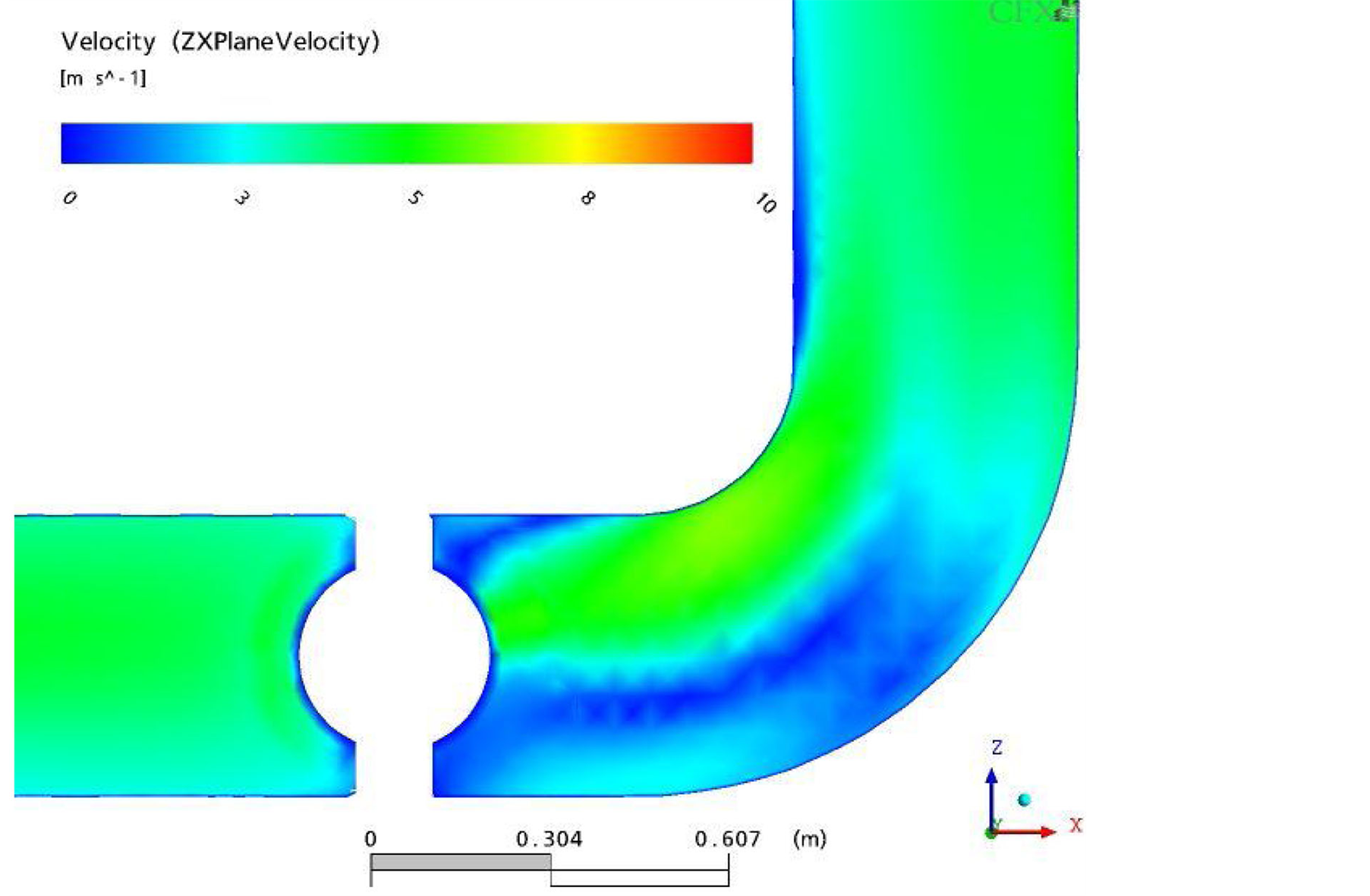
Figures 3-6 present the numerically predicted velocity contour and vector distribution for four different cases, respectively. For the Case 1, Figure 3(a), Figure 3(b) show that flow velocity through the valve is 7 - 8 m/s near the wall and the central part of a 90 degree elbow due to the effect of a big-counter rotating vortex flow near the intrados and extrados regions of a 90 degree elbow. Therefore, this case may be concerned to thin the elbow by the substantial flow disturbance.
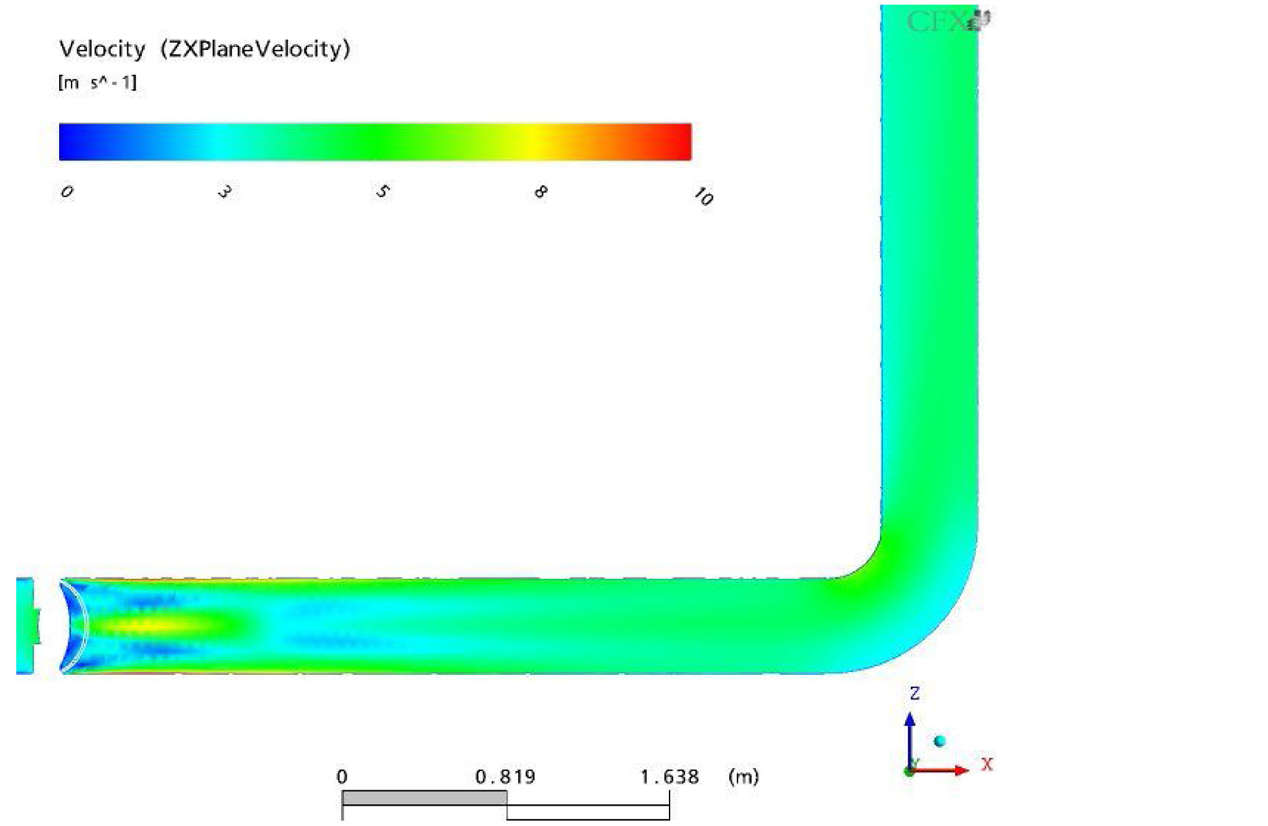
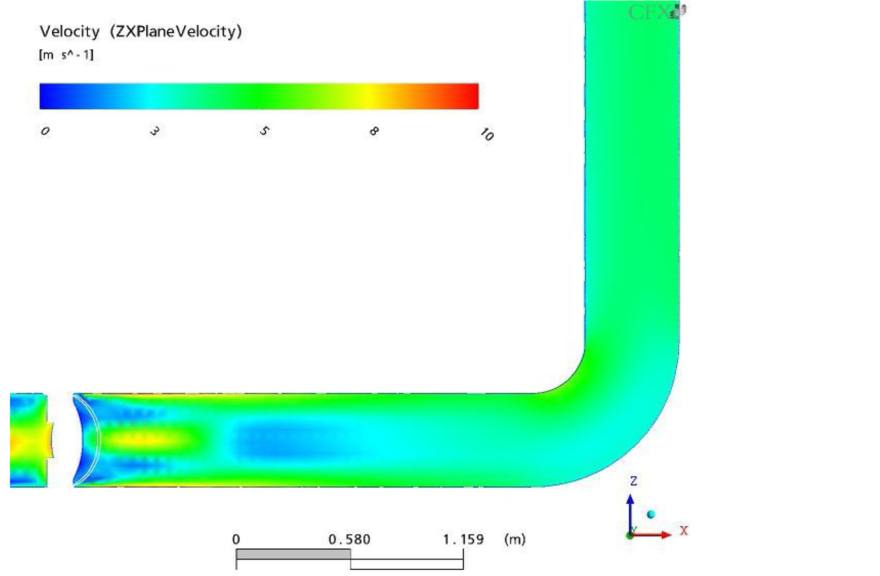
For the Case 2, Figure 4(a), Figure 4(b) present that the flow velocity is 5 - 6 m/s for the corresponding locations comparing with Case 1 and flow disturbance such as vortex shedding is practically nothing happened near
 (a)
(a)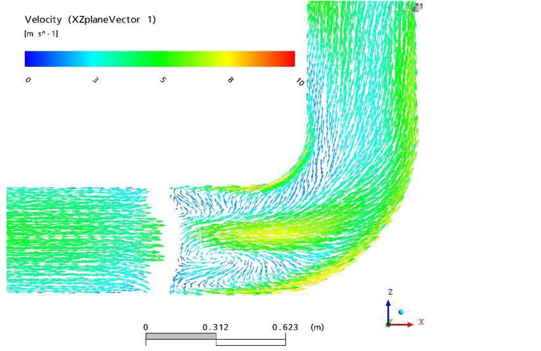 (b)
(b)
Figure 3. Streamwise direction velocity distributions near the 90 degree elbow located at the downstream region through the 60% opened valve (Case 1): (a) velocity contour plot, (b) velocity vector plot.
 (a)
(a)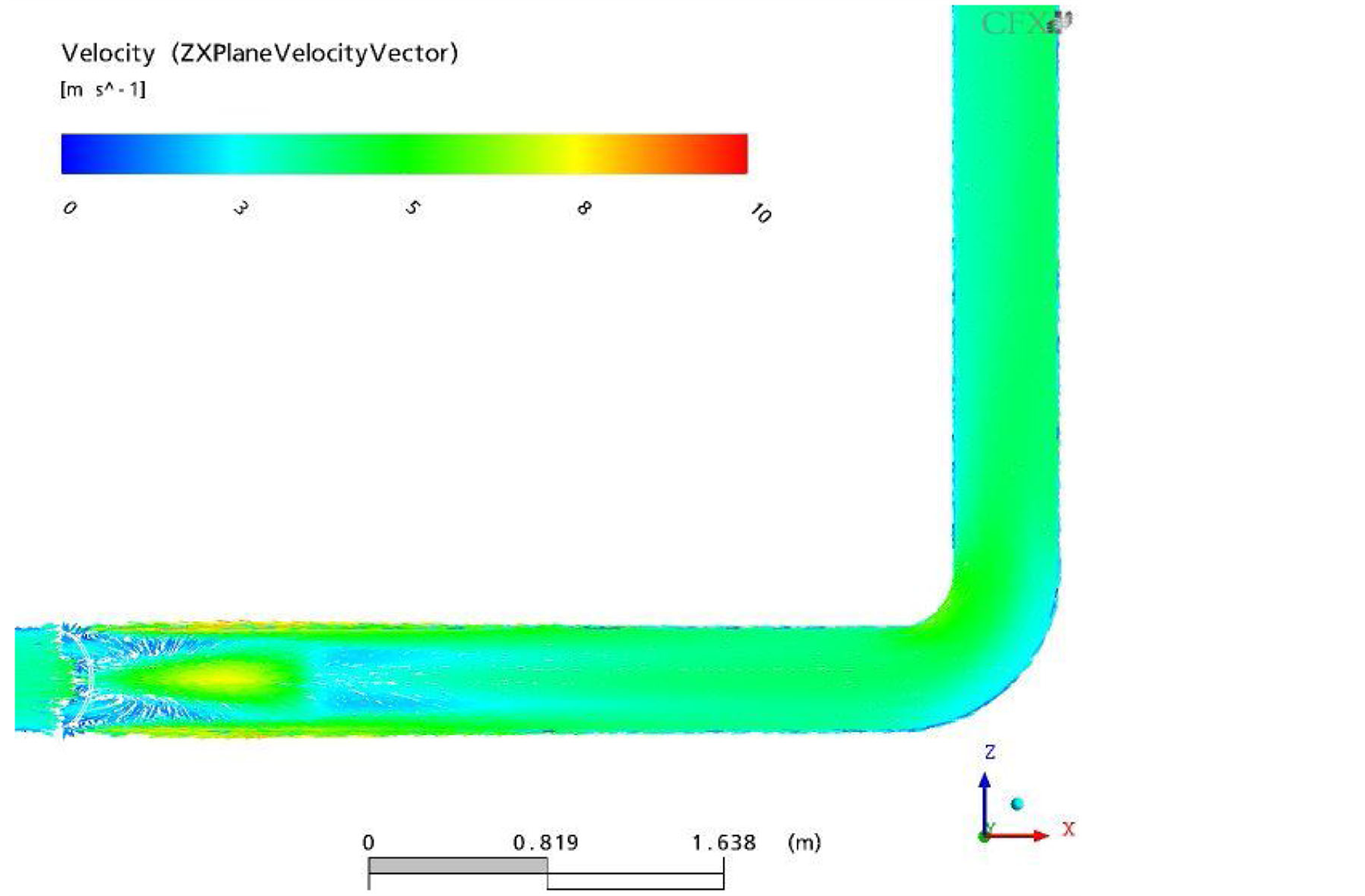 (b)
(b)
Figure 4. Streamwise direction velocity distributions near the 90 degree elbow located at the long straight downstream region through the 60% opened valve (Case 2: L/D ≈ 8, Reference): (a) velocity contour plot, (b) velocity vector plot.
 (a)
(a)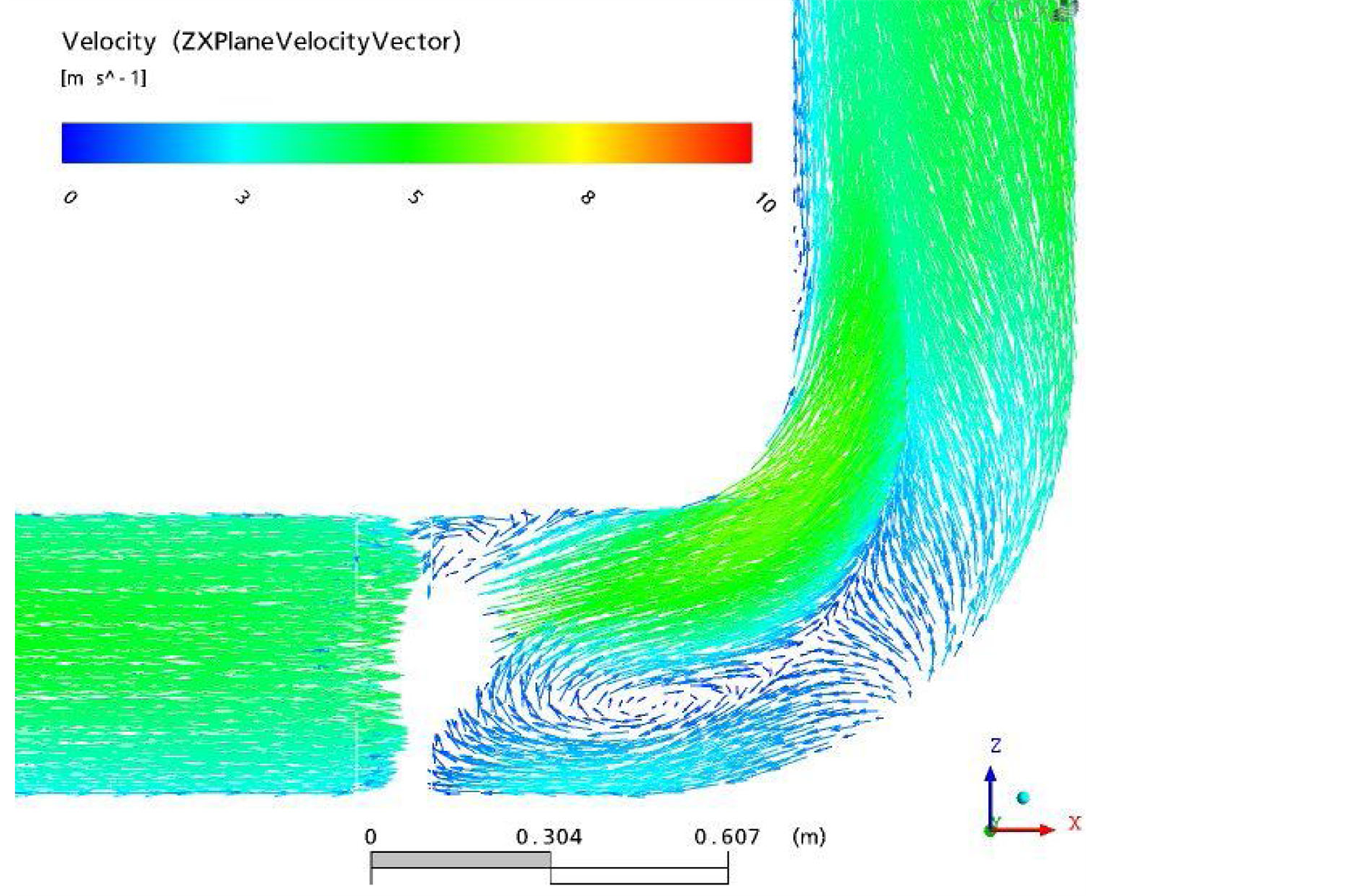 (b)
(b)
Figure 5. Streamwise direction velocity distributions near the 90 degree elbow located at the long straight downstream region through the 100% opened valve (Case 3): (a) velocity contour plot, (b) velocity vector plot.
 (a)
(a)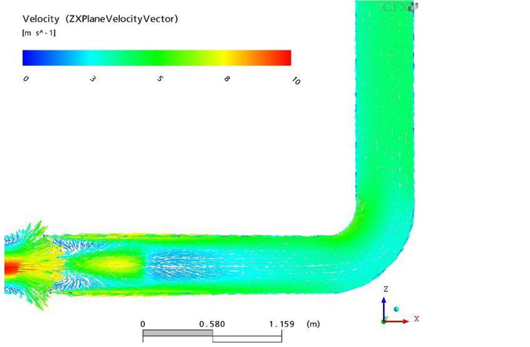 (b)
(b)
Figure 6. Streamwise direction velocity distributions near the 90 degree elbow located at the long straight downstream region through the 60% opened valve (Case 4: L/D ≈ 5): (a) velocity contour plot, (b) velocity vector plot.
the intrados and extrados regions of the 90 degree bended elbow located at the downstream region from the valve because flow is already stable and fully developed through the long straight pipe length.
For the Case 3, Figure 5(a), Figure 5(b) provide that the velocity distribution through the valve is relatively steady because the flow restriction is very small. Operating condition with the fully open valve decreases flow disturbance such as counter-rotating vortex flow at the elbow region. The vortex is observed at the extrados region.
However, the velocity is very low and almost stagnant in that region. Thus, the effect of the vortex would be small and would not threat the piping integrity. For the Case 4, Figure 6(a), Figure 6(b) show that the flow through the valve shows small vortex shedding near the wall part of a pipe line due to the effect of valve open angle and then the flow becomes stable passing through the relatively long straight pipe section. So, in this Case 4 like Case 2 and Case 3, the piping wear such as the wall thinning and pinhole near the intrados of 90 degree upward elbow caused by the flow disturbance is also not happened. Therefore, the velocity distribution at the elbow for Case 2, Case 3, and Case 4 are similar and the effect of flow disturbance hardly occurs to the 90 degree upward elbow region.
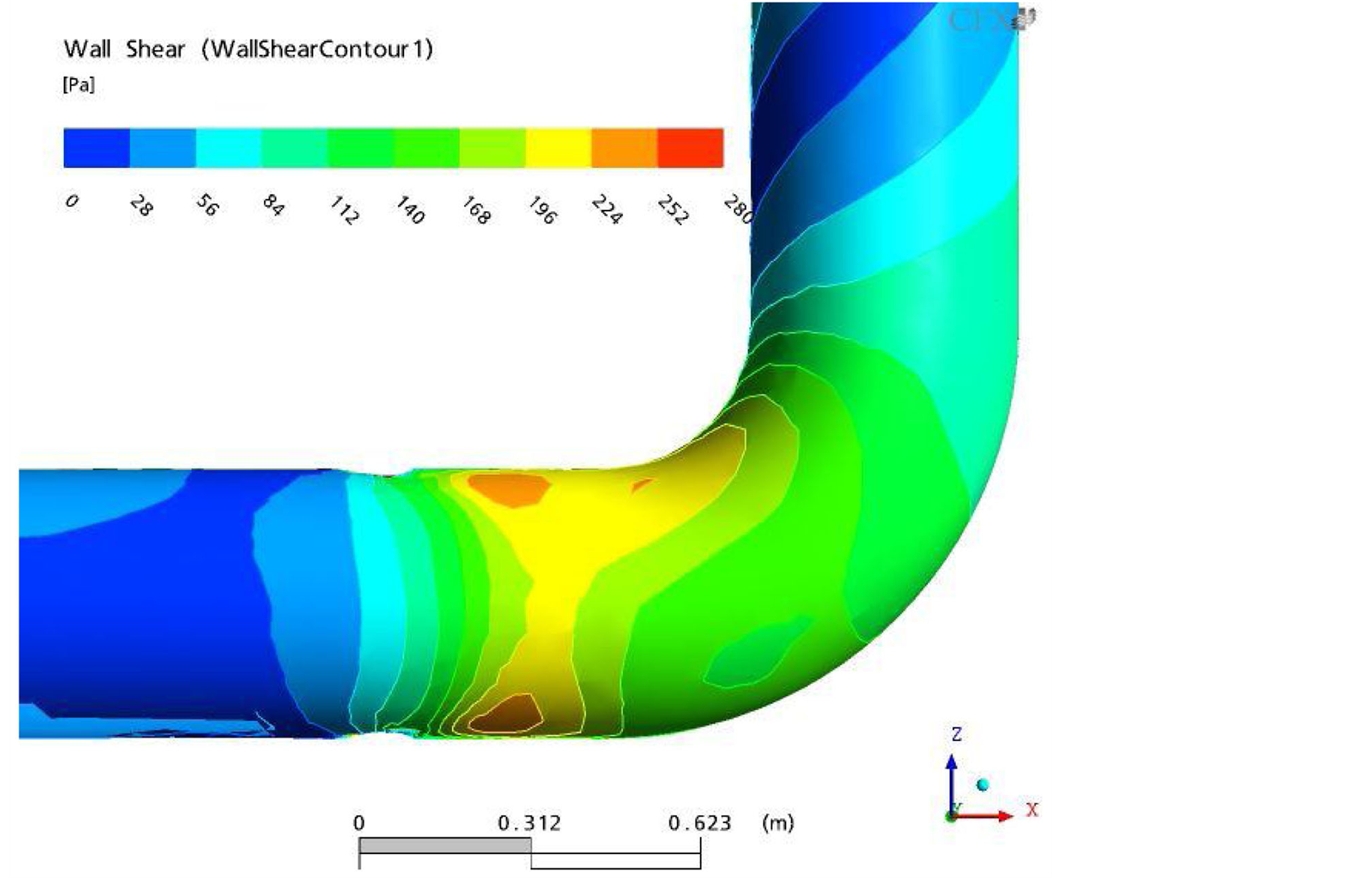
Figures 7(a)-(d) show the distribution of shear stress for four different cases. For Case 1, the shear stress is high, 182 - 200 Pa and the effect of the shear stress is observed from the front part of elbow to the elbow curvature (Figure 7(a)). Specially, the shear stress is high near the intrados region of the elbow. Also, the flow through valve experiences a high disturbance and the flow direction valve experiences a high disturbance and the flow direction has changed approaching the elbow. Thus, if the continuous high shear stress is operated, the integrity of this 90 degree upward elbow should be decreased and degraded. For Case 2 (reference case), the shear stress is about 80 Pa at the elbow (Figure 7(b)). The shear stress gradually increases in a straight piping downstream of the valve and then shear stress slightly increases sharply at the upward wall of the 90 degree bended elbow, the integrity at the intrados region of the elbow keeps healthy comparing with Case 1 (Figure 7(a)). For Case 3 (Figure 7(c)) and Case 4 (Figure 7(d)), the magnitude and distribution of the shear stress are maintained healthy without the degradation because the shear stress is quite low and flow disturbance is little near the 90 degree upward elbow.
 (a)
(a)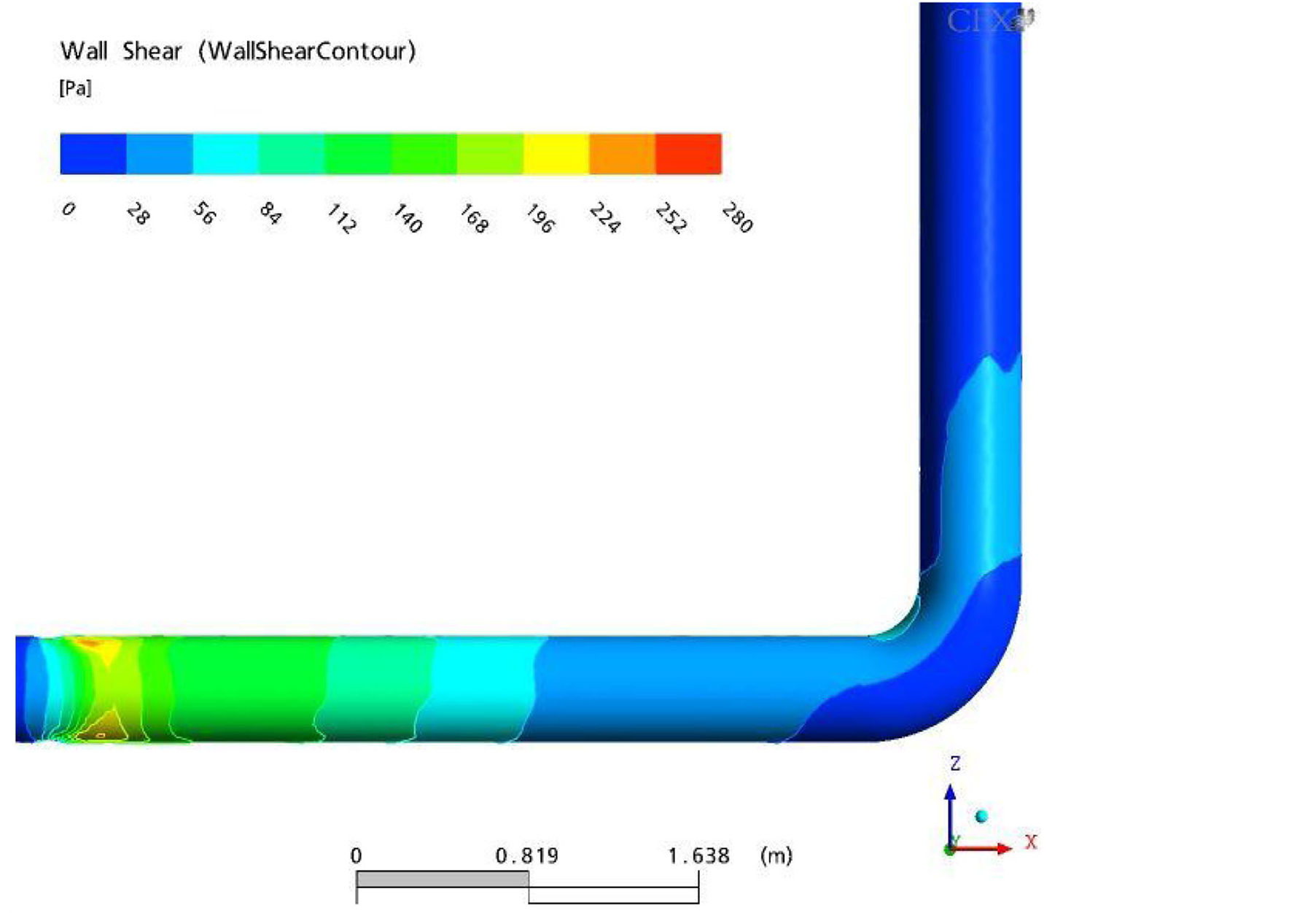 (b)
(b)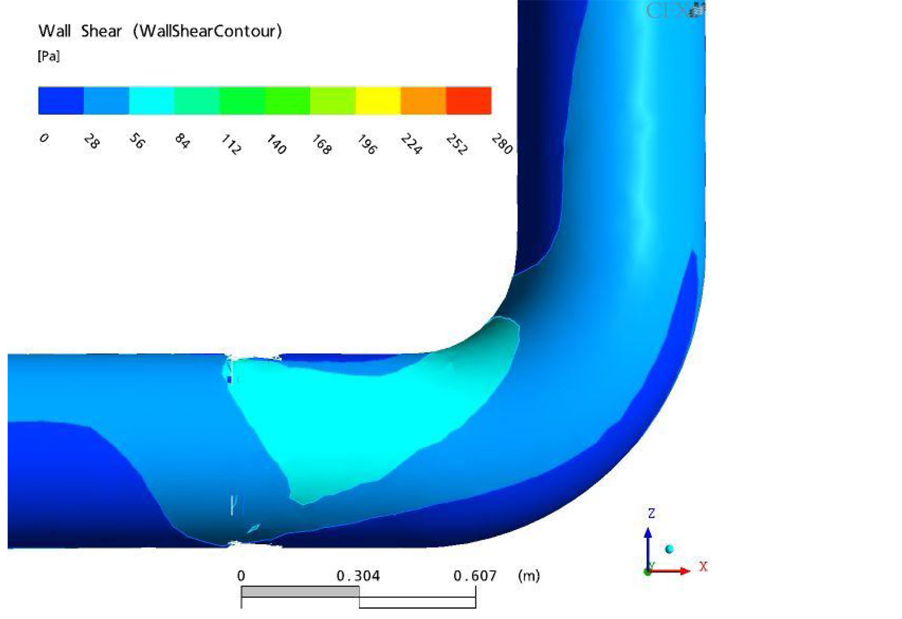 (c)
(c)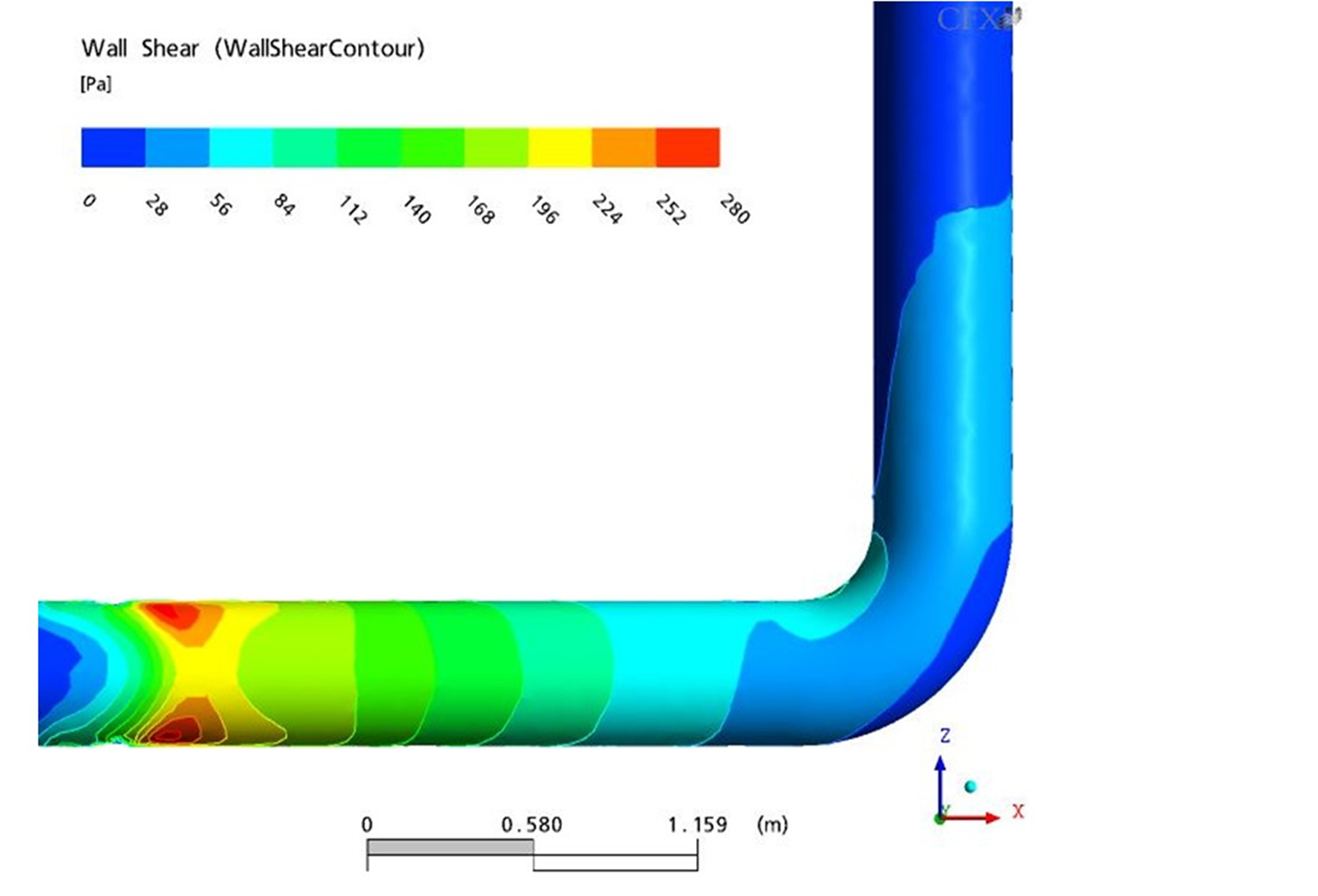 (d)
(d)
Figure 7. Distributions of a shear stress contour for (a) 60% valve open, (b) L/D ≈ 8, (c) 100% valve open, and (d) L/D ≈ 5.
5. Conclusions
The effect of a butterfly valve open angle and the distance between a butterfly valve and a 90 degree bended elbow is examined using CFX code.
Case 1 shows that the flow disturbance at the elbow is substantial and the pipe thinning would be a concern. Case 3, the case with 100% valve open, show the disturbance is similar to the reference case (Case 2). Hence, with the current piping configuration, operating with the fully open valve while regulating flow using a valve upstream could be a solution. Case 4, the case with L/D ≈ 5, shows that the flow disturbance is similar to the reference case. Therefore, the modification of piping configuration to ensure L/D ≈ 5 would be a long-term solution for the example we investigated.
References
- Addy, A.L., Morris, M J. and Dutton, J.C. (1985) An Investigation of Compressible Flow Characteristics of Butterfly Valve. ASME Journal of Fluid Engineering, 107, 512-517. http://dx.doi.org/10.1115/1.3242522
- Eom, K. (1988) Performance of Butterfly Valves as a Flow Controller. ASME Journal of Fluid Engineering, 110, 16-19. http://dx.doi.org/10.1115/1.3243503
- Morris, M.J. and Dutton, J.C. (1989) Aerodynamics Torque Characteristics of Butterfly Valves in Compressible Flow. ASME Journal of Fluids Engineering, 111, 392-399. http://dx.doi.org/10.1115/1.3243658
- Park, S.W. and Lee, S.W. (2000) Three-Dimensional Flow Characteristics in the Downstream Region of a ButterflyType Valve Used in Air-Conditioning System. KSME Journal B, 24, 260-269.
- Barton, N.A. (2003) Erosion in Elbow in Hydrocarbon Production System: Review Document. Health & Safety Executive: Research Report 115.
- EPRI (1998) Application Guide for Motor-Operated Valves in Nuclear Power Plant. EPRI TR-106563-V2.
- Danbon, F. and Solliec, C. (2000) Aerodynamic Torque of a Butterfly Valve: Influence of an Elbow on the Time-Mean and Instantaneous Aerodynamic Torque. ASME Journal of Fluids Engineering, 122, 337-377. http://dx.doi.org/10.1115/1.483262
- Ansys (2005) CFX-10: User’s Manual Version 10, USA.