Modern Mechanical Engineering
Vol.3 No.2(2013), Article ID:31639,8 pages DOI:10.4236/mme.2013.32011
Vibrating Drivers for Transportation
Mechanical Engineering Department, Ben Gurion University, Beer Sheva, Israel
Email: sandler@.bgu.ac.il
Copyright © 2013 Ben Zion Sandler, Vladimir Chapsky. This is an open access article distributed under the Creative Commons Attribution License, which permits unrestricted use, distribution, and reproduction in any medium, provided the original work is properly cited.
Received January 7, 2013; revised March 22, 2013; accepted April 11, 2013
Keywords: Inertial Drivers; Asymmetric Friction Force; Parking Mechanism
ABSTRACT
The movement of objects by means of vibrations is a widely known idea, used for bodies transportation in automated industry based on vibrating bases, on which the transported elements are placed. We consider an inversed idea: vibration is applied to the movable element. Surface, on which this displacement must be realized, is unmovable. The asymmetry of the friction forces in the different phases of the vibration is the cause of motion in this case. A distinctive feature of the proposed device is a slope of the plane of vibration of the inertial mass, which leads to increasing of the asymmetry of friction. In this paper, we consider an example of application of the device to the lateral vehicle parking. The idea is numerically estimated and tested with a laboratory prototype. The movement along a straight line of the trolley with sloped vibrating mechanism under influence of asymmetric friction forces has been estimated and practically simulated with the laboratory prototype.
1. Introduction
In this paper, the author addresses a powerful means for developing new technical concepts, finding novel solutions and solving certain technical problems. It involves a method of thinking that produces results over several different cognitive levels: from the simplest design level in up to the highest conceptual level used to formulate new technical ideas. The method has already been partially described in this author’s book [1].
The movement of objects by means of vibration is the widely known idea, used for transportation different parts and bodies in automated industry based on the use of vibrating bases, on which the transported elements are placed. This vibration is mainly realized by electromagnets and variable voltage. In this paper we consider the inversed idea: the vibration is applied to the moved element while the surface, on which this displacement must be realized, is unmovable.
The most known use of vibration of the object to move it himself is the vibro-hammers, used in the building and mining industries. These designs are mainly intended for movement in the vertical direction. Here, except the inertia forces, the force of weight acts in the vertical direction and leads to the asymmetry of the acting forces. Another situation occurs in devices intended for horizontal movement. In them the difference is caused by the asymmetry of the friction forces, acting on the base at different periods of the movement of the inertial mass, mounted on the base.
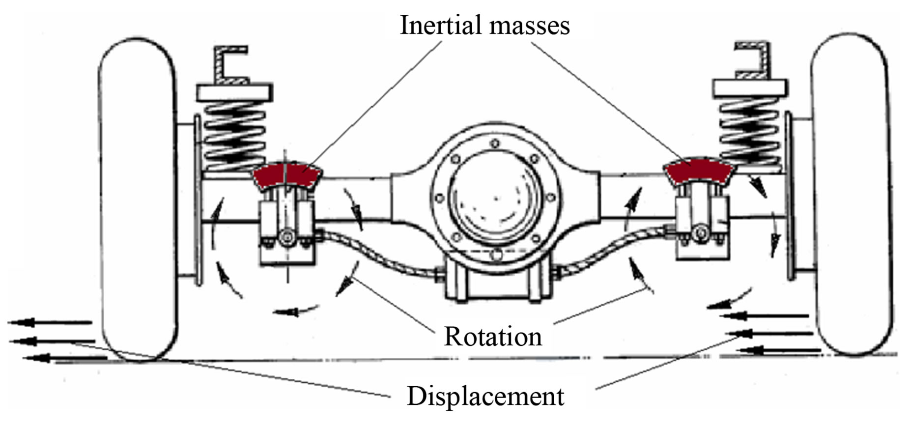
Example of such device is the mechanisms described in the patent USP No. 2639777 [2]. It intended for vehicles parking. In the method described in this patent the difference of friction between the wheels and the road in different phases of the rotation of the inertial mass (Figure 1(a)) is provided by an additional pressure, caused by the force of inertia of the rotating masses. This leads to the displacement of the car (Figure 1(b)). But calculations showed low efficiency of this design.
Search the efficiency of this method has led to a method of inertial driver, described in this article. In the new proposed method, the plane of rotation of the inertial mass is inclined to the line of moving direction. Calculations and simulations show that the proposed method is much more efficient than previously known, and can actually be used in practice. In addition, there are prospects for the use of this type of inertial drives to simply move the mobile objects.
2. Description of the Proposed Mechanism
2.1. Construction
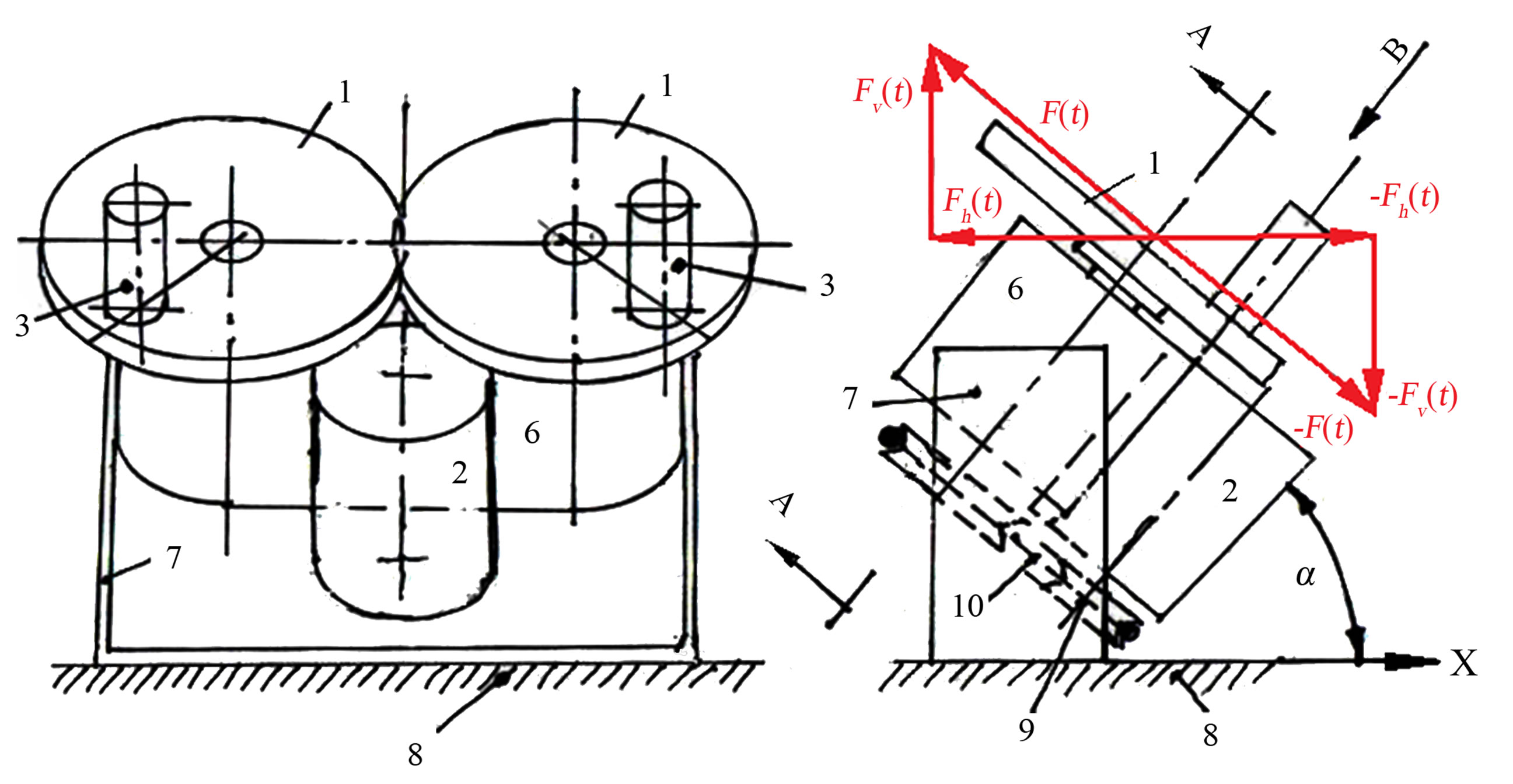
The inclined inertial device is shown in Figures 2(a) and (b). It consists of two identical engage gears (1), driven by motor (2). The gears are equipped with two symmet-
 (a)
(a)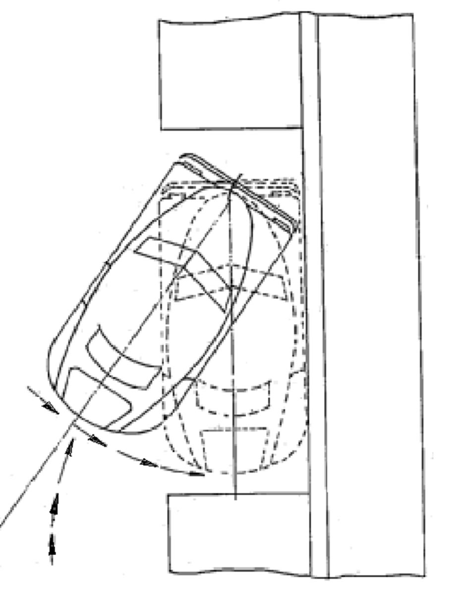 (b)
(b)
Figure 1. Parking of the car. Figures from USP No. 2639777.
rically fixed masses (3). The gears are assembled in a bearing common base (6) by means of two axes 4 and ball bearings (5). The assembly is mounted on a platform (7) at an inclination angle . The platform slides on the surface (8) in the direction X. The transmission of rotation from the motor (2) to gears (1) is provided by two pulleys (9) and belt (10). Two force vectors
  and
and  are created as a result of masses (3) rotation, which influences the normal force creating the friction between surface (8) and the devices support and the driving force moving the body the device is fastened on.
2.2. The Working Principle
We consider the operation of proposed vibration driver mechanism on example of car parking (Figure 3).
Laboratory model that demonstrates this movement is shown in the following video [3].
In following example the proposed mechanism consists from two rotating gear wheels mounted on rear axis of the car at some inclination angle as shown schematically in Figure 4.
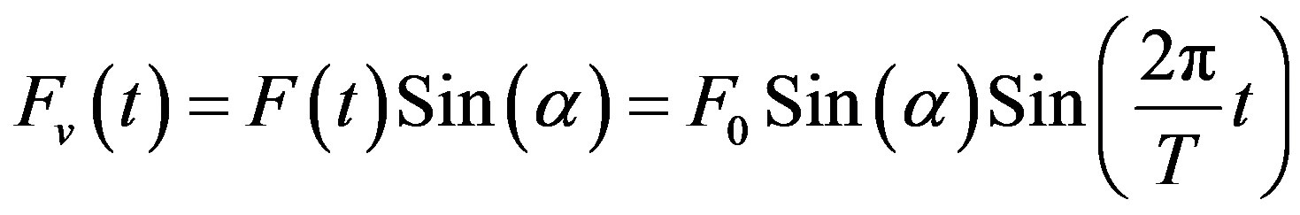
The working principle is based on difference between friction forces, acting in two half-periods of wheels rotation. The rotation of the inertial masses, fixed on the disks, in the opposite direction leads to inertia forces, acting on the car, in the direction perpendicular to the line connecting the centers of disks ( in Figure 4). The components of inertial forces, acting along the line, connecting the centers of disks, are equals and opposite in direction, so they cancel each other out. If the rotation of the discs is with a constant angular velocity
 , then the function of inertia forces versus time is of a harmonic function with frequency f, as shown in Figure 4.
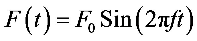 (1)
(1)
where  is magnitude of the inertial force, created by two rotating masses:
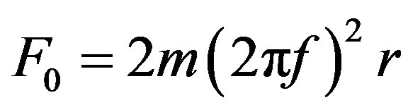 (2)
(2)
m, mass of one inertial body; f, the frequency of rotation of the discs in Hertz units (or rotations per second); r, the distance between the centers of mass of the inertial bodies and the centers of the rotating disks.
The vertical component of force  changes the pressure on the car axle, and consequently changes the force of friction in the different phases of the rotation of the discs. The horizontal component of harmonic force
  together with the different friction forces in the different phases of the discs rotation, leads to the movement of the car.
2.3. Calculation of the Angle of Car Displacement
In common case the movement of the car consists of three parts in each period of disc rotation: 1) sliding, the motion with friction, when the horizontal component of force is greater than the friction force and the vertical force component is less than the weight of the moving object; 2) hovering above the road, when the vertical component of force is greater than the weight of the moving object (which leads to its flying); 3) deceleration, motion in the presence of the friction force after touching the road.
Let’s assume some restrictions on the physical model for considered here numerical examples (the estimated quantities are approximate):
• The friction index does not depend on the motion speed;
• Vehicle mass is much greater than the inertial mass of rotating bodies;
• The magnitude of the loading force, acting on bearing of rotating rings does not exceed 10,000 Newton;
• The rotation speed of the rings does not exceed 1200 rpm.
As shown in Figure 3, the car’s back part is mowed inside the free place due to the vibrating driver. The same way, after the device is rotated for 180 degrees, it can be used for bringing the car out of the parking place by moving it reverse.
For the numerical example of the calculation of turning the car, we will take the geometric and physical pa-
 (a)
(a)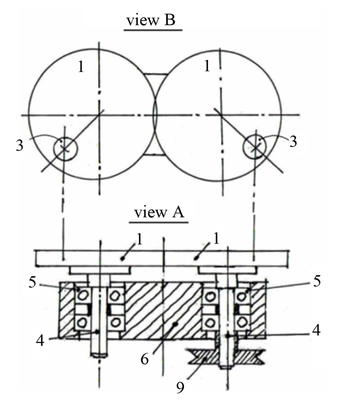 (b)
(b)
Figure 2. General view of the vibrations generating device.
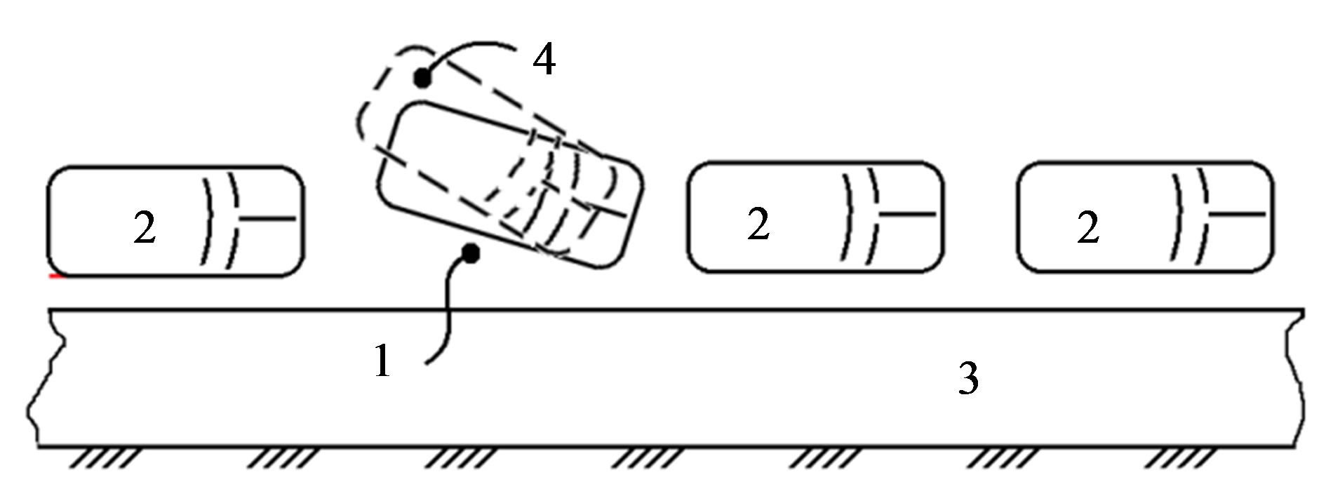
Figure 3. Lay-out of the parking place 1 in a street near the side walk 3. Car 2 finishes the parking process by moving its back part 4.
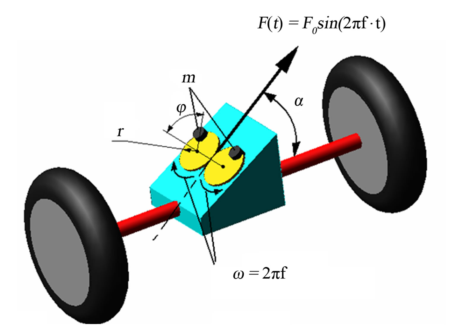
Figure 4. Schematic diagram of the back car’s axe with inclined inertial device, mounted on it.
rameters of the vehicle and the inertial unit close to the real. Here are the following data:
• mass of the car is ;
;
• distance between rear and front axles is  meters;
• moment of inertia of the car relative to center of the front suspension ;
;
• pressure on the rear axle due to gravitation weight of the car is  (Newton);
• radius of rotation disc is  meter;
• mass of the inertial body ;
;
• rotation speed is 1200 rpm ;
;
• inclination angles are ;
;
• index of friction is ;
;
• the permissible load on the bearings of the rotation discs assumed as .
.
The purpose of the calculation is to estimate the angular displacement of the car relative the center of front suspension for all given α during one cycle, one second, and ten seconds.
For definiteness, the initial conditions assume as:
• The discs are already spinning with angular velocity 
• At the time  the position of the inertial body
 .
.
• The car is not moving.
1) Sliding. For calculation of the first part of displacement, when car moves with friction, the time, when car starts to move and time when car starts to hover should be defined. Also, we need to define the equation of motion in horizontal direction.
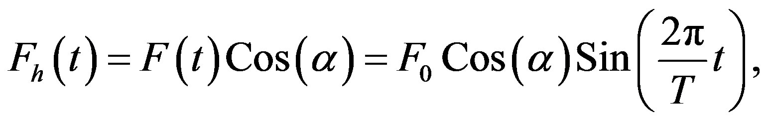
Let  be the time function of the vertical component of the inertial force
 :
:
 (3)
(3)
where  is the period of disc rotation. F0, magnitude of the inertial force (Equation 3);
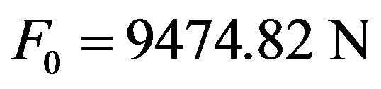 . (The load on the bearings Fb = F0/2 = 4737.41 N is less than permissible.
At the time, when the vertical component of inertial force equals or greater than the pressure force on the rear car axle, it breaks away from the road.
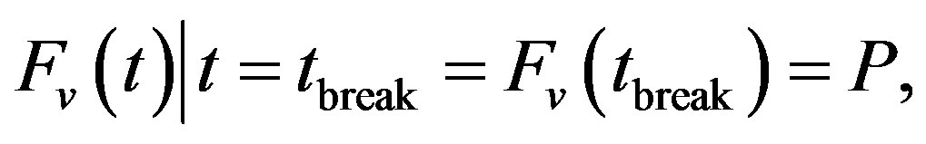 (4)
(4)
The break time tbreak was calculated from Equations (3) and (4). The graphs of function  for different inclination angles and the break time tbreak were calculated using the Wolfram’s Mathematica 8 software, shown in Figure 5. As shown in Figure 5, for
  tbreak = 0.0067 seconds. As can be seen from Figure 5, in the current example only for α1 the hovering takes place. Thus, further we consider the current example separately for
 , and then for
  and
and .
.
Determination of time tstart when back part of the car starts to move transversal with friction, sliding.
The condition for horizontal moving is the horizontal component of the inertial force becomes greater than friction force. The following equation expresses this condition:
 (5)
(5)
where , the magnitude of horizontal component of inertial force.
From Equation (5) implies that:
 and
and
 (6)
(6)
Equation (6) is true for all  and
and . Calculation gives the following:
Let  be the horizontal component of the inertial force
 ,
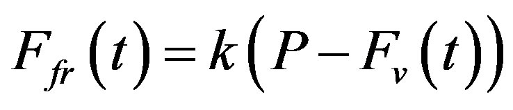
,  be the locomotive power, defined as difference of horizontal component of the inertial force and force of friction
 :
:
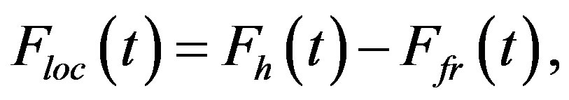
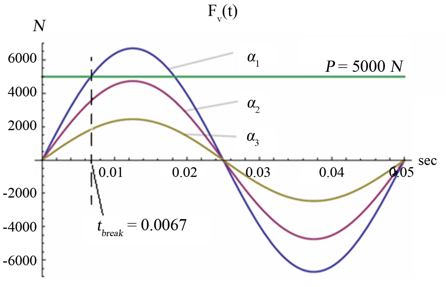
Figure 5. Vertical component of the inertial force versus time for different inclination angles of the plane of rotation discs.
where:
 (7)
(7)
 (8)
(8)
The moments of the corresponding forces relative to center of the front axle are:
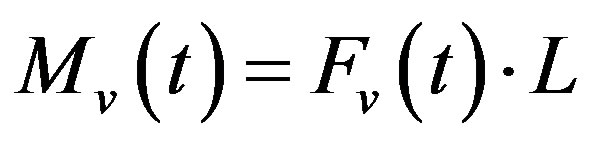 , the moment of vertical component of inertial force,
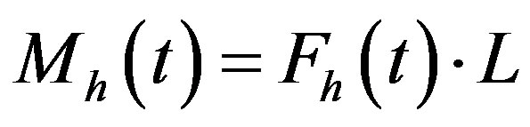 , the moment of horizontal component of inertial force,
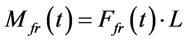 , the moment of friction force,
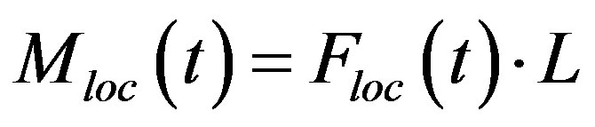 , the moment of locomotive powerwhere L, the distance between rear and front axles.
The angular acceleration of the car relative to center of front axle, caused by moment of locomotive force during first part of motion (sliding):
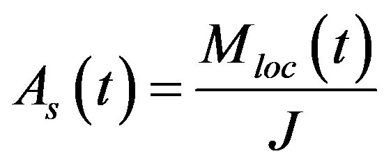 (9)
(9)
Graphs of function  versus time for different inclination angles of discs plane are shown in Figure 6.
The angular velocity  of the car relative to center of front axle as function of time is calculated by integration of the function
  over time and is represented in Figure 7.
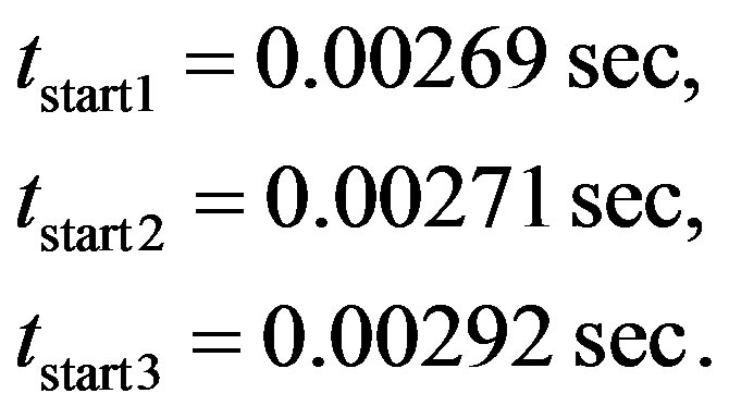
The area under velocity plot from t = tstart1 = 0.00269 sec to . numerically equals to angular displacement
  of the car during one cycle. The result of calculation gives
  and the angular velocity at the time of breaking
 :
:
 (10)
(10)
2) Hovering. The second part of the motion is the movement of a car under the action of gravitational and inertial forces, without touching the road with an initial velocity.
The vertical component of the initial angular velocity equals to zero. Equation of the second part of motion (hovering) in vertical direction looks as follows:
 (11)
(11)
where , vertical component of angular acceleration during hovering;
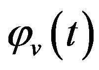 , angular displacement in vertical direction during hovering as function of time. The numerical representation of Equation (11) and graph of function
  for inclination angle
  is shown in Equation (12) and Figure 8.
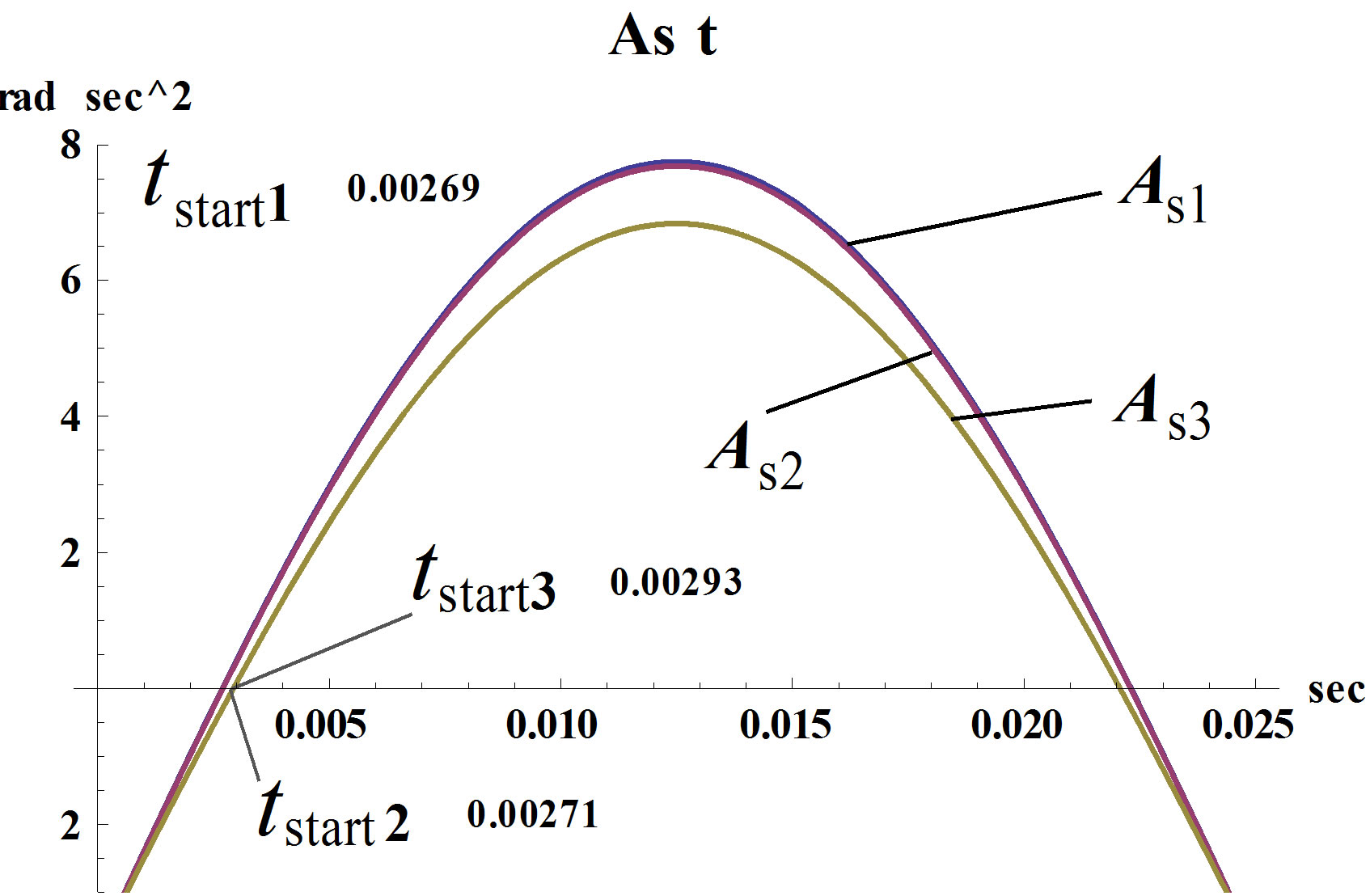
Figure 6. Horizontal angular acceleration of the car during sliding and friction on the road as a function of time.

Figure 7. The horizontal angular velocity of the car for inclination angle α1 during sliding.
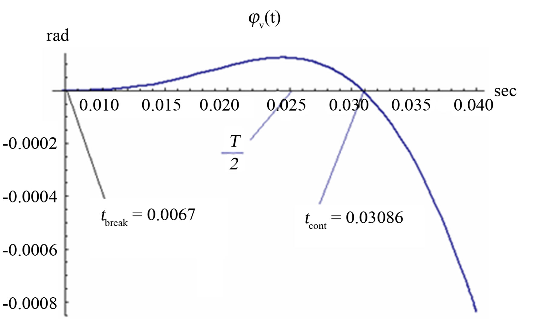
Figure 8. Vertical angular displacement φv(t) during hovering as function of time.
 (12)
(12)
Obviously only positive values of the vertical displacement make sense. Figure 8 shows that contact with the road exists in the second half of the period T of disks rotation. It means that after the time of  inertial force acting opposite the movement of the car and slows it.
The horizontal component of the initial angular velocity equals to the angular velocity at the time of breaking . Equations of the second part of motion (hovering) in horizontal direction looks as follows:
 (13)
(13)
Or in the numeric representation:
 (14)
(14)
where , horizontal component of angular acceleration during hovering,
  , horizontal component of angular velocity during hovering,
  , angular displacement in horizontal direction during hovering.
Figure 9 shows the horizontal component of angular velocity  of the car relative to center of front axle as function of time. The area under velocity plot from
 to
to . Numerically equals to the angular displacement
  of the car during one hover. The result of calculation gives:
The horizontal component of angular velocity at the time of contact with road is:
 (15)
(15)
3) Deceleration. We assume that the collision with the road was of the nature of the inelastic and there was no rebound. Thus, the third part of movement is the horizontal sliding with presence of friction force with initial angular velocity  under action of the moment of horizontal component of inertial force
 . The
. The
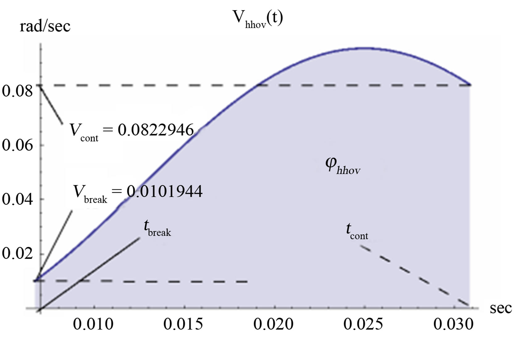
Figure 9. Angular velocity of the car in horizontal hovering, as a function of time (without friction).
equations of motion for third part are the same, as for the first part, but with other initial conditions. There are as follows:
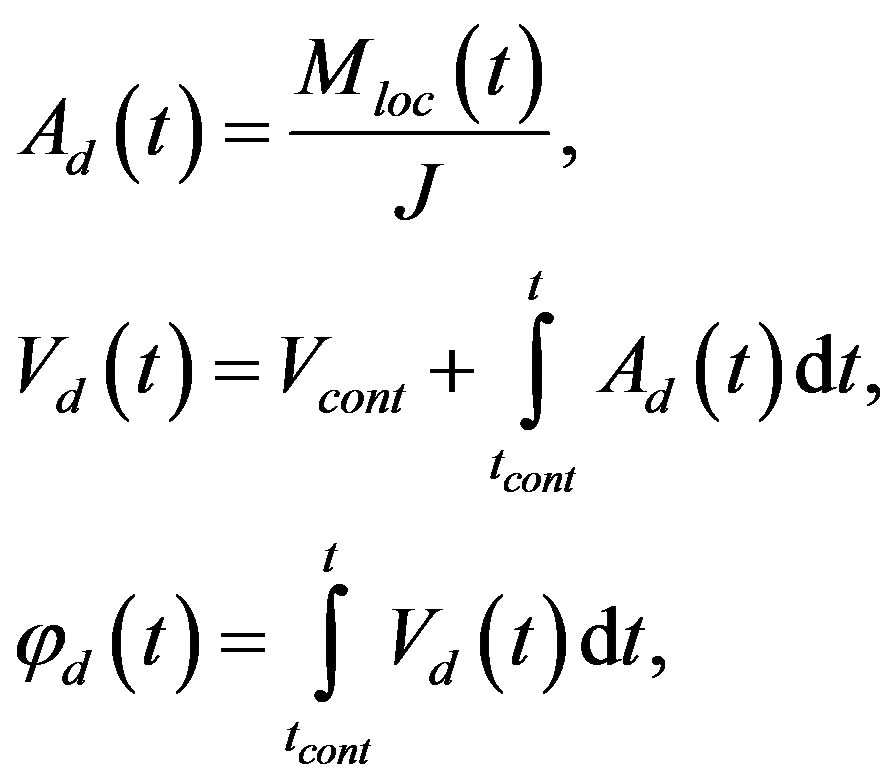 (16)
(16)
where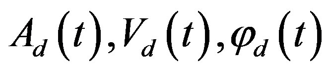 , are the angular acceleration, velocity, and displacement during the third part of movement (deceleration). Numerical representation of the angular velocity
  is follows:
 (17)
(17)
Graph of this function is shown in Figure 10. The area under the graph of  numerically equals to angular displacement of the car during part of deceleration:
 (18)
(18)
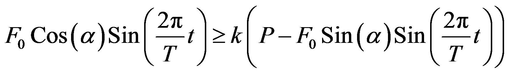
Finally, the absence of a reverse movement should be checked. For this purpose, the model must satisfy the following condition: the value of horizontal force less than the value of friction force,  , for
, for , or, according to Equation (5):
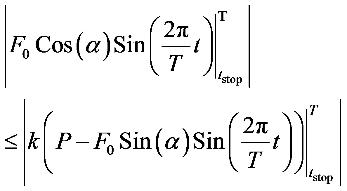 (19)
(19)
Graphs of left and right sides of Equation (19) are shown in Figure 11.
As clear from Figure 11, the condition of Equation (19) is satisfied. Reverse movement during deceleration is absent.
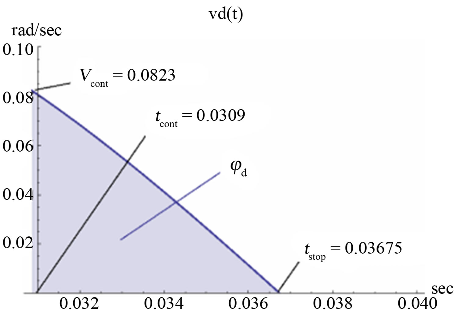
Figure 10. Angular velocity of car’s movement during horizontal deceleration, as a function of time.
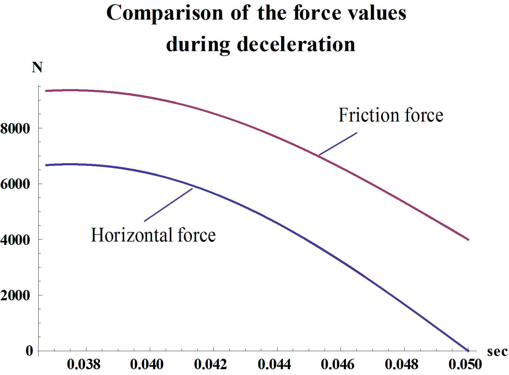
Figure 11. Comparison of the force values during deceleration.
Full rotation in one cycle is the sum of three parts of angular displacement:
 (20)
(20)
The full rotation in one second is:
 (21)
(21)
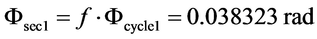
The full rotation in fifteen seconds is:
 , or in degrees:
 (22)
(22)
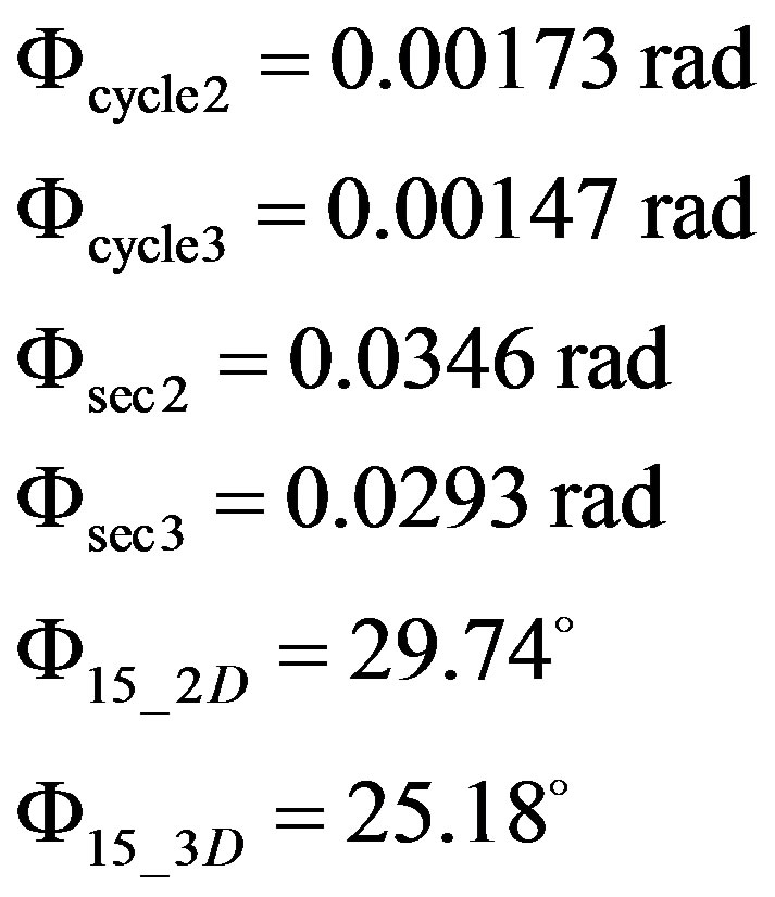
The calculations of the angular displacements for inclination angles  and
and  were performed in the same way as for Parts 1 and 3 of previous calculation, but only for continuous time range from
  to
to . The corresponding start times, which have been calculated previously by Equation (6), are:
 ,
, 
By integration of function of angular acceleration of the car Equation (9) the function of angular velocity for  and
and  should be obtained. The results of calculations are follows:
 (23)
(23)
The graphs of listed functions are shown in Figure 12.
The angular displacements numerically equal to arias under graphs , and should be calculated by integration in time range from tstart to tstop.
 (24)
(24)
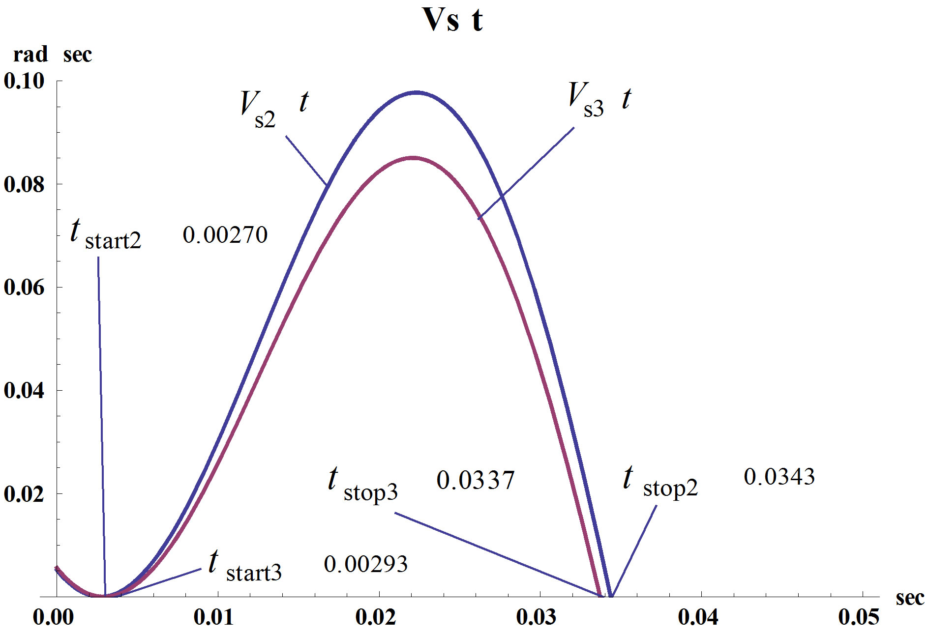
Figure 12. Function of angular velocity during sliding for inclination angles α2 = 30˚ and α3 = 15˚.
The results of calculations showed that the proposed model of the inertial drive with inclination angle of discs plane 30˚ - 45˚ is acceptable for use for car parking.
2.4. Some Possible Improvements of the Proposed Devise
The above example shows the opportunity to apply the proposed inertial drive for parking a small car. Some additional design solutions can enhance the capabilities of the devices, described above.
A design in which exists the possibility of rotation of the device around the vertical axis by 180˚, will allow the car both, to enter inside a parking place and out of it.
The ability to change the angle (α) of the plane of disks rotating will change the parameters of the lateral movement of the car according to the coefficient of friction between the tires and the road surface.
For heavy goods vehicles the inertial unit with four or more rotating inertia bodies can be used. The schematic drawings of such units are shown in Figure 13 or in Figures 6 and 9 in the patent 4050527 “Vibrodriving apparatus” [4].
3. Brief Discussion about Linear Displacement of the Vehicle
As it is obvious from the description of the operating principle of the proposed inertial drive, it can also be used for different other vehicles. A necessary condition is the creation as much as possible difference in the friction forces between the vehicle and the road, acting in the various phases of the rotation of the inertial drive. Rectilinear movement of the vehicle with the inertial drive on the normal wheels in the presence of rolling friction (which is much less than sliding friction) is not effective. To use the above described model with the inertial drive for the rectilinear motion of the vehicle, its design shall ensure the presence of the forces of sliding friction.
Experimental Model Examination
An example of this design is the model of a trolley with inertial drive, which is shown in the following video clip [5].
In this trolley, the back axle was stalled and was loaded with additional weight, for increasing the force of sliding friction. Also, the line of action of the inertial force passes through the rear axle of the trolley that increases the effect of the vertical component of the force of inertia on value of pressure on the rear axle (Figure 14).
The front swivel wheels provide a stable direction of the trolley motion because in the direction of rectilinear motion acts the force of rolling friction, but in the transverse direction acts the force of sliding friction between rubber tires and the floor, which is much larger than rolling friction.
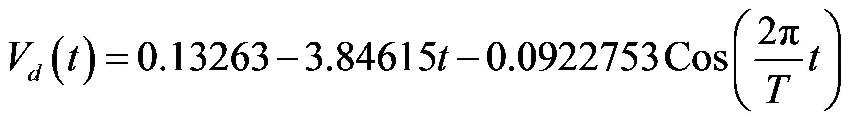
Calculations using the algorithm described above for car parking (for the sliding motion) gave results similar to those observed in the video clip. The trolley has an average speed of 11.3 cm/second, slightly more than in the video clip (~10.8 cm. per second.). Measuring the distance traveled by the trolley is represented by the graph in Figure 15.
Approximation section  (interrupted line) obviously can be described by a simple formula of the following form:
 (25)
(25)
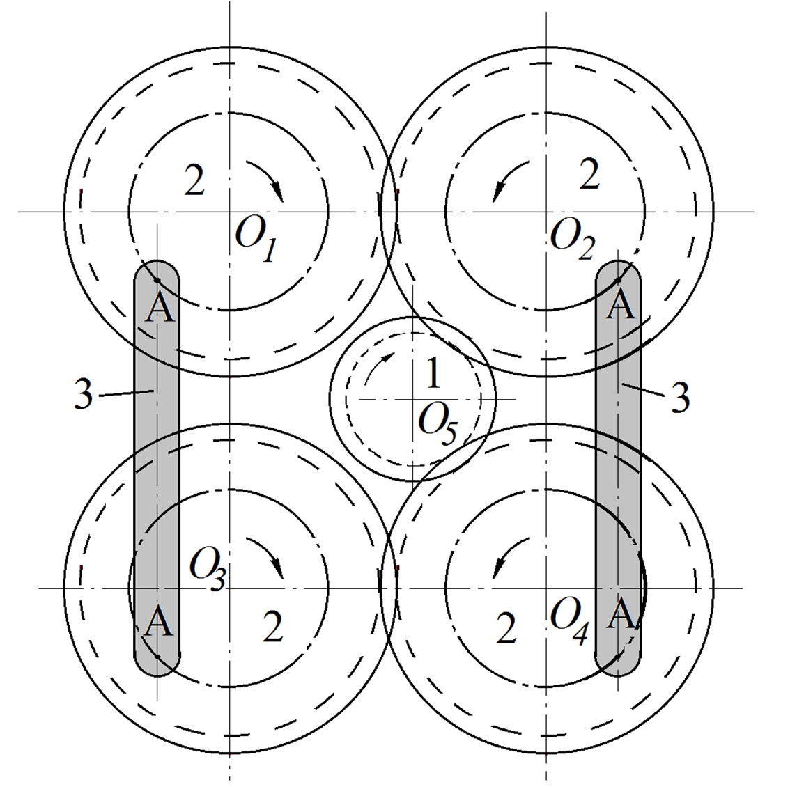
Figure 13. Inertial unit, consisting of four rotating discs (2) with inertial bodies (3), driven by gear (1).
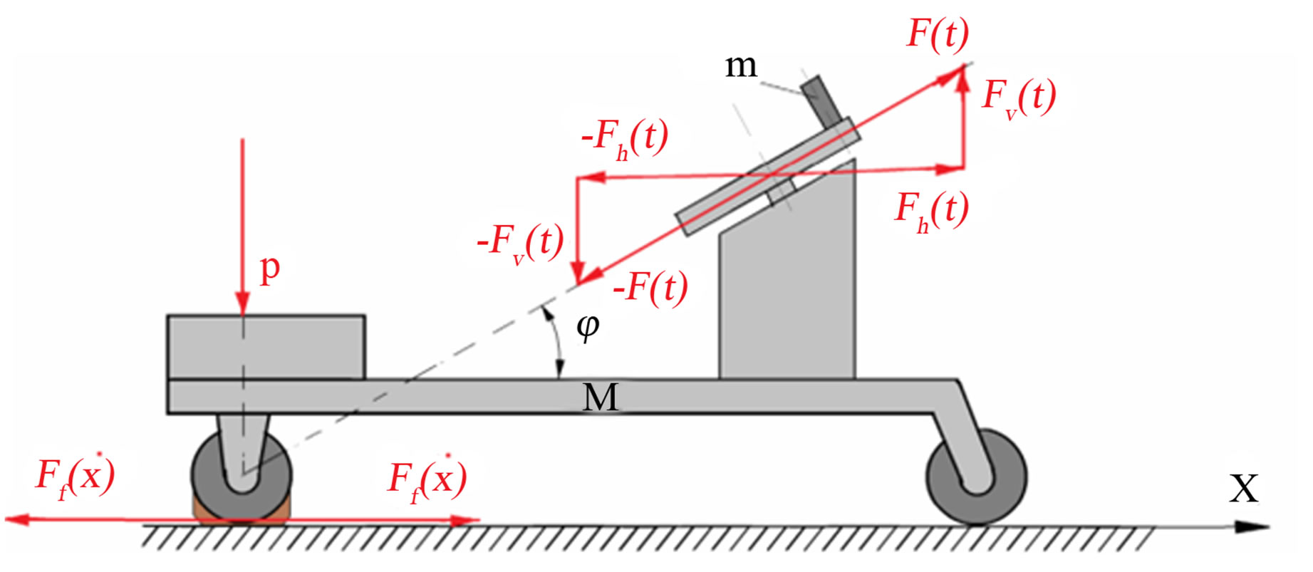
Figure 14. Lay-out of a platform moving by the inertial driving mechanism.
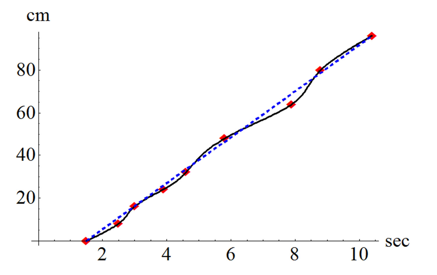
Figure 15. Displacements of the trolley versus time (according to test, shown in the video clip). A linear approximation of the “motion versus time” is also shown in this Figure.
(Time is taken from about ~1.5 seconds without movement, which is about 15 cm, while further it moves with the speed about 10.8 cm/sec for about t = 10 sec).
4. Conclusion, Some Possible Designs
We consider this paper as an example mainly describing the first steps in the design process. The step, where the main idea of the solution, answering the formulated problem the design task requires, must be found, at least one answer, or a number of them. At this stage, the main accent is put on the lay-out or model of the solution. It can be found in already existing designs, or inversed existing idea, or somehow changed, improved existing idea. A consideration of this approach and description of it are given, for instance in some author’s books [1,2] and others.
Technical Proposals for Transportation
We are speaking about mechanical dynamic vibrations as a reason to create certain displacement of a car, improving the parking possibilities. This dynamic mechanical effect, as is here reminded, is widely used in industry.
We inversed this idea by deciding to vibrate the back of the car (not the surface the car is standing on) in such a way moving it to the needed place. Another change, which we propose in our design, is not to use electromagnets as a vibration source, which is often used in industrial machines, usually automatic, for transportation parts. We propose pure mechanical vibrator design (see Figure 2). The simplest consideration brings us to think about counterbalance fly-wheels used in rail-way engines or locomotives. The same solution is sometimes used in crank-shaft mechanisms. The cranks and wheels usually rotate in vertical plane, which makes the inertial forces appearing here not appropriated to create driving the mechanism to certain direction. To reach the effect of certain movement direction, the orientation of the vibrating device in space must be changed and the direction of the driving force must be strictly defined. This is achieved in the given here solution (Figure 2).
An idea to drive by the device, considered in Figure 2, placing it on elastic bases, say, on 4 rubber balls. This may be a specific device, on which the vibrator can be directed in the needed way. Such a device may be a simple toy or a special used carriage.
REFERENCES
- B. Sandler, “Creative Machine Design, Design Innovations and the Right Solutions,” Paragon House Publishers, New York 1985.
- M. L. Dull, “Method and Device for Imparting Lateral Movement to an Automobile,” US Patent No: 2639777, 1953.
- Video Clip in YouTube. http://www.youtube.com/watch?v=B3p4zH4992c&feature=relmfu
- J. L. Lebelle, “Vibrodriver Apparatus,” US Patent: 4050527, 1977.
- Video Clip in YouTube. http://youtu.be/Owu2ANuwPLw