Open Journal of Metal
Vol.2 No.1(2012), Article ID:18315,6 pages DOI:10.4236/ojmetal.2012.21003
Thermal Stability of Ni-Fe Alloy Foils Continuously Electrodeposited in a Fluorborate Bath
1Key Laboratory of Ethnic Medicine Resource Chemistry, State Ethnic Affairs Commission and Ministry of Education, Yunnan University of Nationalities, Kunming, China
2College of Chemistry and Chemical Engineering, Hunan University, Changsha, China
Email: abrastein@163.com
Received January 15, 2012; revised February 12, 2012; accepted February 21, 2012
Keywords: Iron-Nickel Alloys; XRD; Electrodeposition; Fluorborate
ABSTRACT
Nanocrystalline Ni-Fe alloy foils were fabricated by using a continuous electrodeposition system, and then they were annealed at different temperatures ranging from room temperature to 650˚C. A ductile-brittle-ductile evolution of these alloy foils was observed along with the increase of annealing temperature, and was affected by iron content. The first and second transformation took place at below 300˚C and over 500˚C, respectively. Iron improved thermal stability of nanocrystalline Ni-Fe alloys. The XRD data indicated that for Ni100–xFex (x > 55) alloys bcc to fcc phase transformed at 300˚C and completely at 500˚C.
1. Introduction
Due to their magnetic and mechanical properties, Ni-Fe alloys have been a focus of many researchers. Nanocrystalline Ni-Fe alloys can be easily prepared using an electrodeposition method [1-17]. Li et al. [9-16] electrochemically deposited nanocrystalline Ni100–xFex (x = 15, 21, 45) alloys in a sulfamate-sulfate bath, and studied in detail their thermal stability and mechanical properties. They found that the Ni-Fe alloys possessed high tensile strength (such as Ni85Fe15 alloy, 2.4 GPa [15]). The wonderful tensile properties of the nanocrystalline Ni-Fe alloys allow them to be applied as a mechanical carrier.
Nanocrystalline Ni-Fe alloys exhibit poor thermal stability and their grain growth has been observed at relatively low homologous temperatures [9,18,19]. The mechanical properties (such as tensile strength) of Ni-Fe alloys are related with the grain size [14,15]. As a grain refiner and compressive stress reagent, saccharine is usually added into the baths to decrease the grain size and the tension stress of Ni-Fe alloys. Saccharin, however, enhances the sulfur content in alloy electrodeposits [20]. Due to the inclusion of sulfur impurity, the Ni deposits exhibit a sulfur embrittlement phenomenon [21,22]. Some researchers considered that Mn [21] and Re [22] can prevent the sulfur embrittlement of Ni deposits. It was found that iron can prevent partially the sulfur embrittlement.
Bright and flexible Ni100–xFex (30 < x < 73) alloy foils have been mass-produced by our group using a continuous electrodeposition technique in a fluorborate bath. The effects of pH value, temperature, electrode rotating speed and iron content of the bath on Ni-Fe alloy composition and plating current efficiency were studied by means of a rotating cylindrical electrode [23]. The electrodeposition process of Ni-Fe alloys in the bath was also investigated by our group [24]. In this paper, the effect of annealed temperature on the embrittlement of Ni-Fe alloys was investigated. The relationship between embrittlement and XRD patterns was also discussed.
2. Experimental
A fluoborate bath was used to continuously electrodeposit Ni-Fe alloys, whose composition can be found in [23]. Ni-Fe alloy foils with different iron content were deposited on a cathodic drum, detached from its surface, then rinsed by water, dried by hot wind, and lastly coiled by a motor. The whole process was completed automatically using self-made equipment.
Ni-Fe alloys were annealed in a vacuum tube furnace (<10 Pa) for 1h at temperatures of 200˚C, 300˚C, 500˚C and 650˚C. The heating rate was 5˚C/min, and the cooling rate was 1˚C/min.
Based on the standard ASTM B 490-92, the ductility of Ni-Fe alloys was analyzed. Because obtained results have a significant operator dependence, the bend test was performed as follow: Ni-Fe alloy shims with a thickness of 30 µm were folded 90˚ and 180˚ (θ) along a line on the shims.
X-ray diffraction patterns of the samples were recorded using a D/max-r A diffractometer with Ni-filtered and raphite-monochromatized Cu kα radiation operating at 50 kV and 100 mA over 2θ-range of 20 - 90 degree. The Ni-Fe shim with a length of 300 mm, a width of 12.5 mm, and a thickness of 9.5 μm was employed for tensiletesting using a Universal Material Testing Machine according to the criterion of GB/T 228 - 2002.
3. Results and Discussion
3.1. XRD Patterns of As-Deposited Ni-Fe Alloys
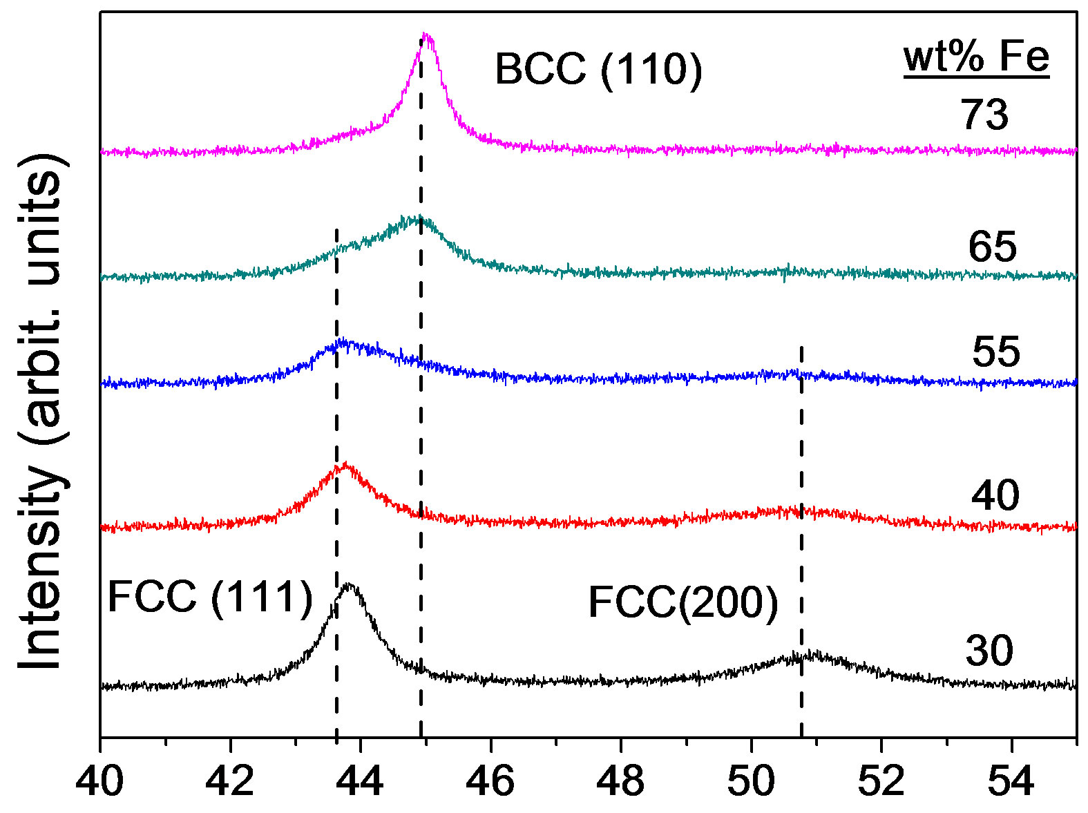
Figure 1 shows the XRD patterns of as-deposited Ni-Fe alloys with different iron content. It can be seen that the phase transformation from fcc to bcc occurs when iron content in Ni-Fe alloys increases from 30% to 73%. Alloys with Ni100–xFex (55 < x < 65) exhibit mixed fcc and bcc phases. However, the iron range of Ni-Fe alloys with mixed phases is about from 40 to 95 (wt% Fe) as Figure 2 shown. The preferred orientations are (111) and (200) reflections for fcc phase and (110) reflection for bcc phase. The (200) peak degrades with the increase of iron content. The results are in agreement with those of Ni-Fe alloys obtained in a rotating cylindrical electrode [23]. The data indicate that the as-deposited Ni-Fe alloys are metastable.
The Ni-Fe alloy grain size obtained from XRD data is comparative with those results of TEM [13,15]. In the present study, the grain size was analyzed using the XRD line broadening analysis of the (111) peak for fcc Ni-Fe alloys and the (110) peak for bcc Ni-Fe alloys by means of the MDI Jade 5.0 software. The grain sizes of Ni-Fe alloys with 30%, 40%, 55%, 65% and 73% iron were 9.7, 8, 4.7, 5.6 and 12.1 nm, respectively. For pure fcc Ni-Fe alloys, the grain size decreased with the increase of iron content. This result is in good agreement with that of Ni-Fe alloys prepared in other baths [7]. Over 55% iron, the grain size, however, increased with the increase of iron content. This grain size reversal may be due to the formation of bcc phase.
3.2. Thermal Stability of Ni-Fe Alloy Foils
As we know, saccharin, a typical organo-sulfur compound, can refine grain size of deposits but induce the sulfur impurity into nickel [22] or Ni-Fe alloy deposits [19]. It was considered that the sulfur impurity resulted in the thermal embrittlement of deposits [21,22]. Dini et al. [25] indicated that the low-melting-point Ni-NiS2 formed in the grain boundaries, thus destroying cohesion between grains as the temperature increased. Sulfur segregation in the grain boundaries had also been detected in Ni and Ni-Fe alloys by Hibbard [19]. Some researchers added Mn [21] and Re [22] into the Ni bath to co-deposit with Ni, and these Ni-Mn and Ni-Re alloys prevent the
 2θ (deg)
Figure 1.X-ray diffraction patterns of as-deposited Ni-Fe alloys with different iron contents.
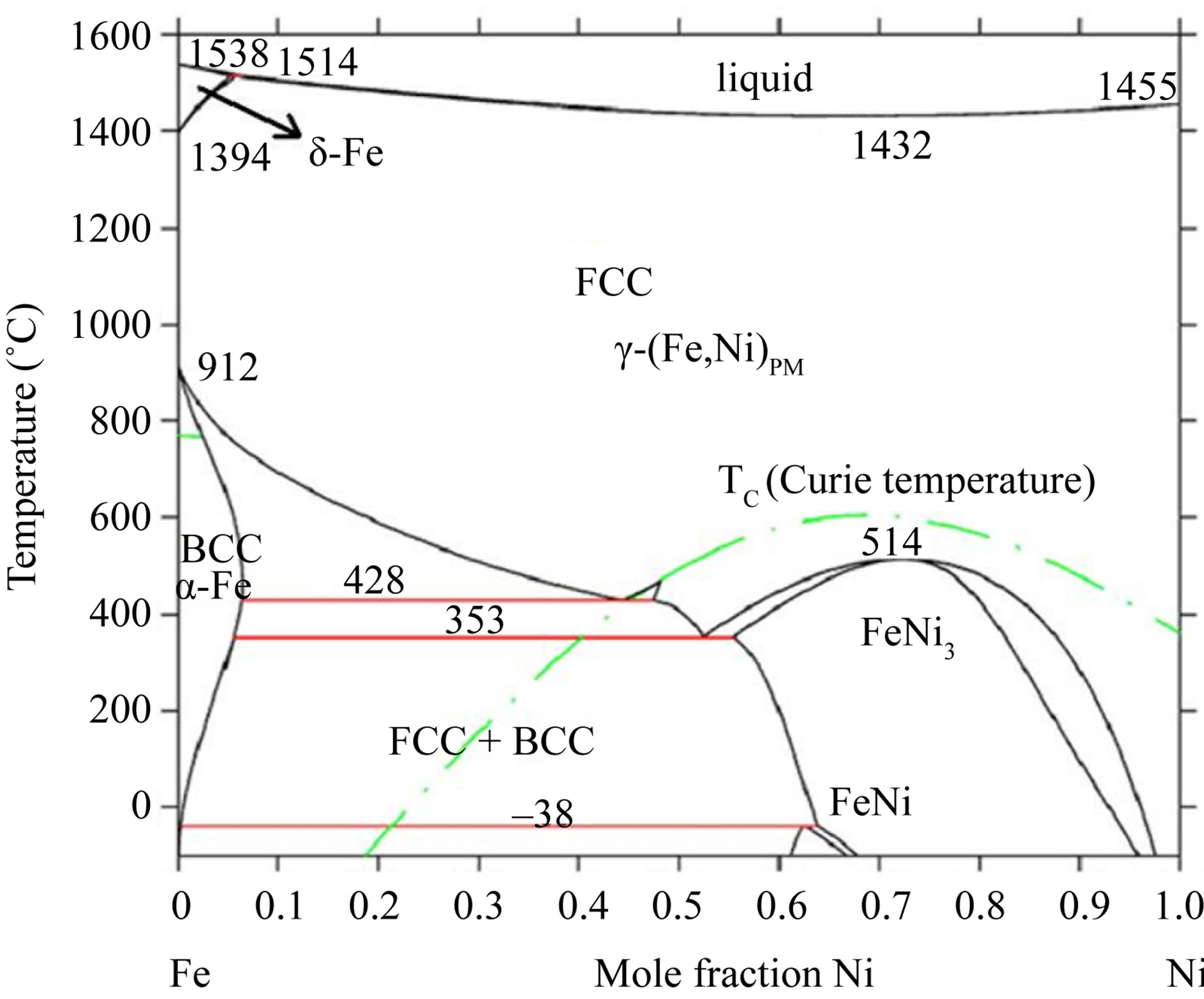
Figure 2. The Fe-Ni phase diagram from a literature [26].
sulfur embrittlement.
Table 1 shows the ductility of the Ni-Fe alloys annealed at different temperatures. All as-deposited Ni-Fe alloys exhibit ductile. For all Ni-Fe alloys, it can be seen that a ductile-brittle-ductile transformation process ˚C occurred when the annealing temperature increased.
It was found from Table 1 that the embrittlement region became narrower when iron content increases, implying that Fe also inhibits the sulfur embrittlement.
But these Ni-Fe alloys did not exhibit an embrittlement property any more, after they were annealed at a high temperature (for example 650˚C), indicating that the ductile-brittle-ductile transformation is irreversible. Views of ductile and brittle Ni-65% Fe alloy foils annealed respectively at 650˚C and 200˚C were shown in Figure 3.
Figure 4 shows XRD patterns of the Ni70Fe30 alloy annealed at different temperatures. The strongest diffraction peak of (111) rapidly became high along with the annealing temperature, implying a growth of alloy grains. For example, at 200˚C the grain of this alloy grew from
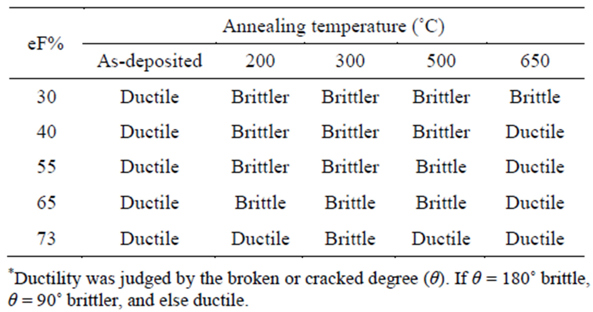
Table 1. Ductility* of the Ni-Fe alloys annealed at different temperatures.
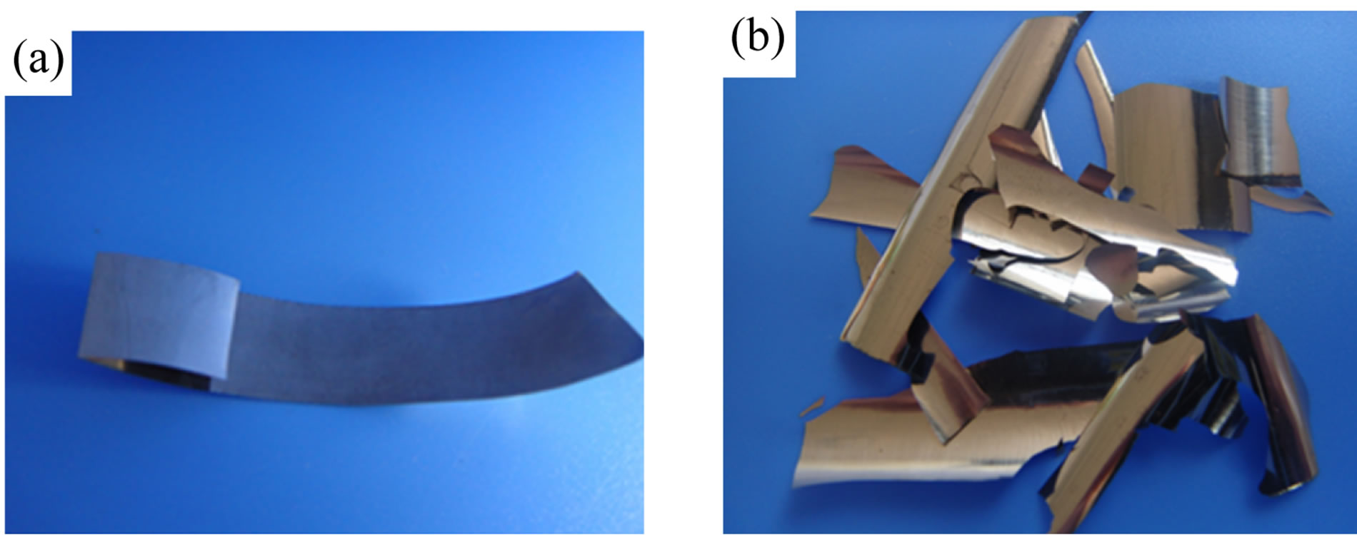
Figure 3. Views of (a) ductile and (b) brittler Ni-Fe alloy foils.
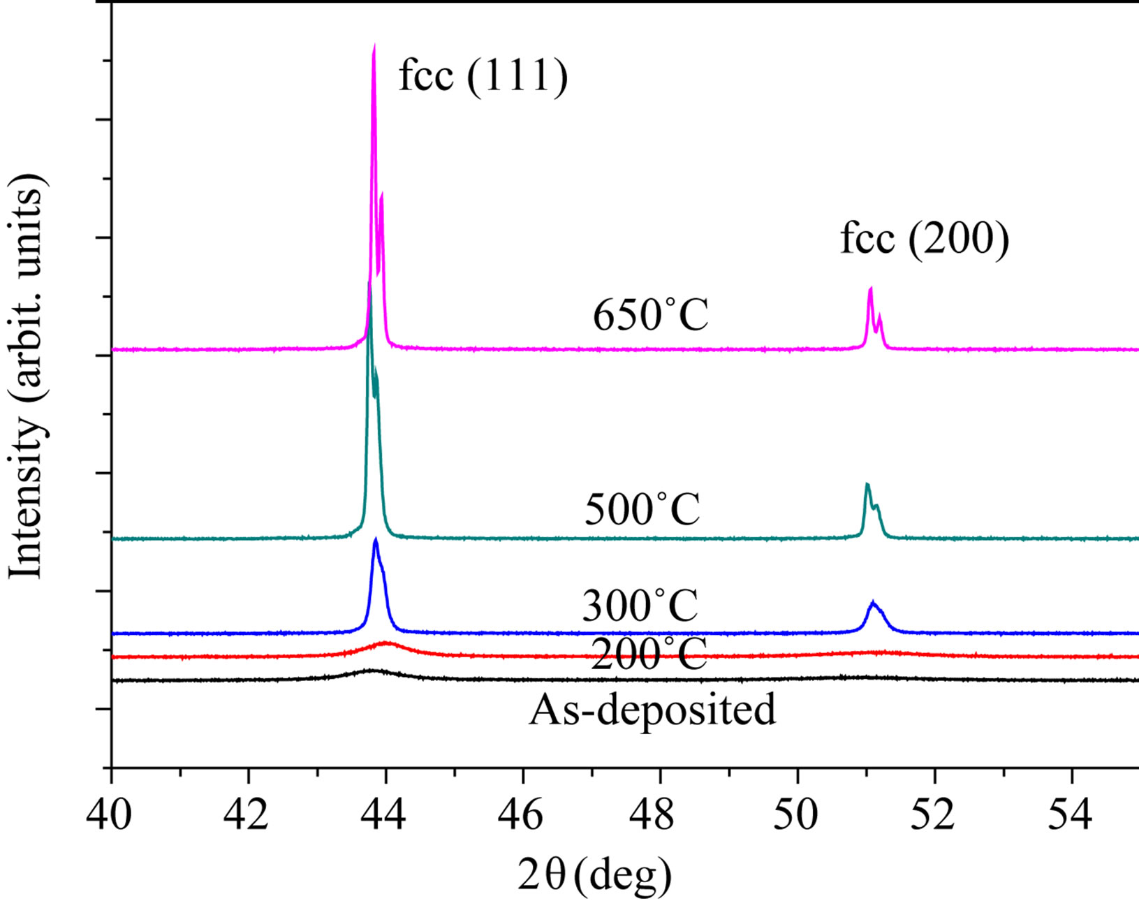
Figure 4. X-ray diffraction patterns for the Ni-30% Fe alloy annealed at temperatures.
9.7 to 12 nm calculated by the MDI Jade 5.0 software. However, a rapid grain growth took place at 300˚C, this temperature corresponds closely with that of electrodeposited Ni-Fe alloys reported elsewhere [13,18,19]. Additionally, as expected in Figure 2 the annealing did not lead to phase change.
It can be observed from Figure 4 that the (111) diffraction peak showed right-left-right shift along with the increase of annealing temperature. At low temperatures (<300˚C) sulfur should segregate to grain boundaries, resulting in brittleness transformation [21,22,25]. Thuvander [19] considered that rather than being caused by diffusion the observed sulphur segregation in nanocrystalline nickel may be a drag effect of moving grain boundaries. Hence, the (111) peak hardly shift.
At high temperatures (for example 500˚C), segregated sulfur gets dissolved interstitially into the bulk lattice, which leads to an increase in lattice constant, and concomitantly to a decrease (i.e. a shift to the left) in diffraction angle. It cannot, however, explain the shift to higher Bragg angles (the right) at 650˚C. At the temperature, irreversible brittle-ductile transformation in the Ni-Fe alloys occurred and was affected by Fe content in these alloys. The results indicated that the Sulfur might disappear from the bulk lattice by formation of sulfide precipitate contained Fe.
The evolution of XRD patterns of Ni60Fe40 is similar to the Ni70Fe30 alloy, and consequently the data were not shown here.
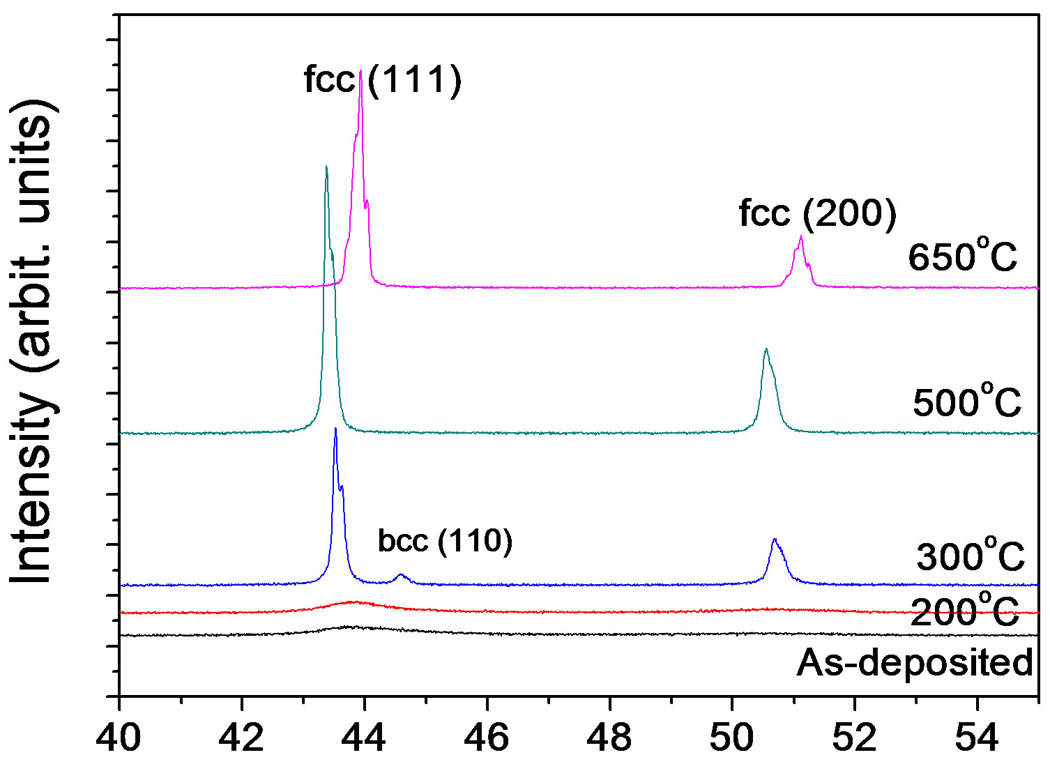
Figure 5 shows XRD patterns of the Ni45Fe55 alloy annealed at different temperatures. At 300˚C, the alloy exhibited also a rapid grain growth, and presented mixed phases with fcc (a main phase) and bcc, according with the Fe-Ni equilibrium phase diagram (Figure 2). When Ni-Fe alloys are annealed at higher than the γ-(Fe, Ni) phase boundary temperature (about 428˚C for the Ni45Fe55 alloy), the bcc phase is hardly observed in the Figure 5, although there is a driving force for the formation of Fe rich bcc phase during the cooling process. The reason is likely that the formation of bcc phase is under kinetic control. Dokania et al. [27] demonstrated the bcc to fcc phase transition for Invar by short pulse laser treatment, and found that the fcc phase became gradually a main phase with increasing the pulse times. This indicated that the role of heat treatment is the same as that of laser treatment.
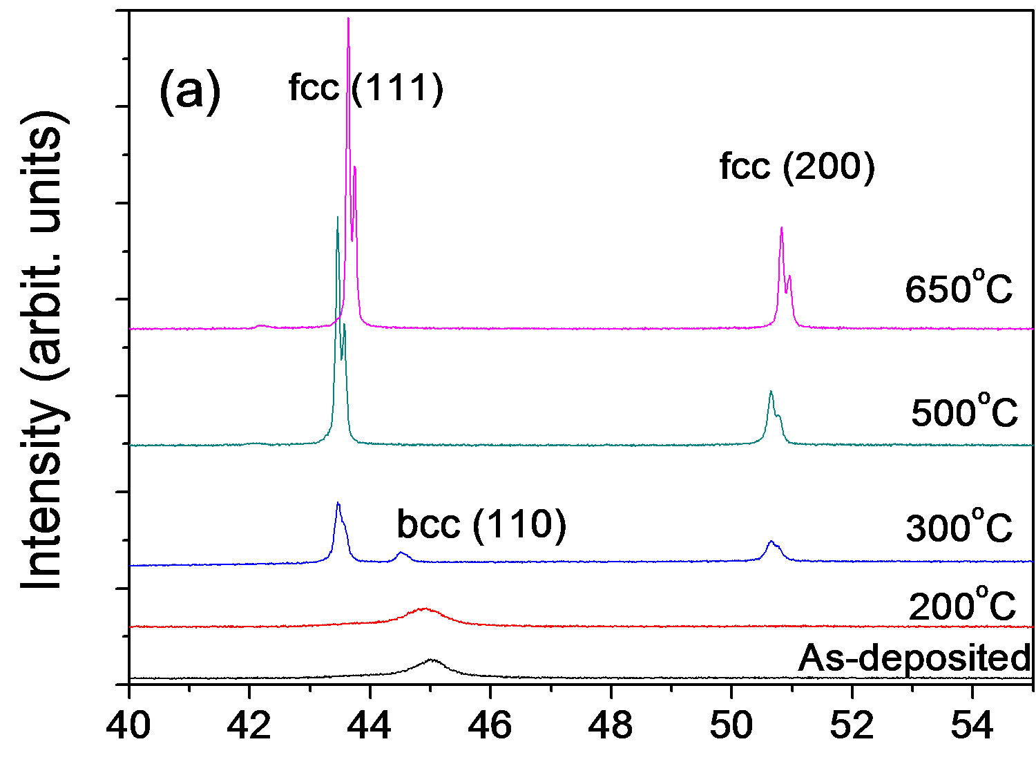
Although the as-deposited alloys exhibited a different phase, namely bcc, the evolutions of XRD patterns of the Ni35Fe65 and Ni27Fe73 alloys (see Figure 6) are similar to that of the Ni45Fe55 alloy. It can be seen that at 300˚C the fcc phase is still a main phase, indicating that its formation is under thermodynamic control. For the Ni27Fe73 alloy, a difference was that diffraction peaks shift to right
 2θ (deg)
Figure 5.X-ray diffraction patterns for the Ni-55% Fe alloy annealed at temperatures.
 2θ (deg)
 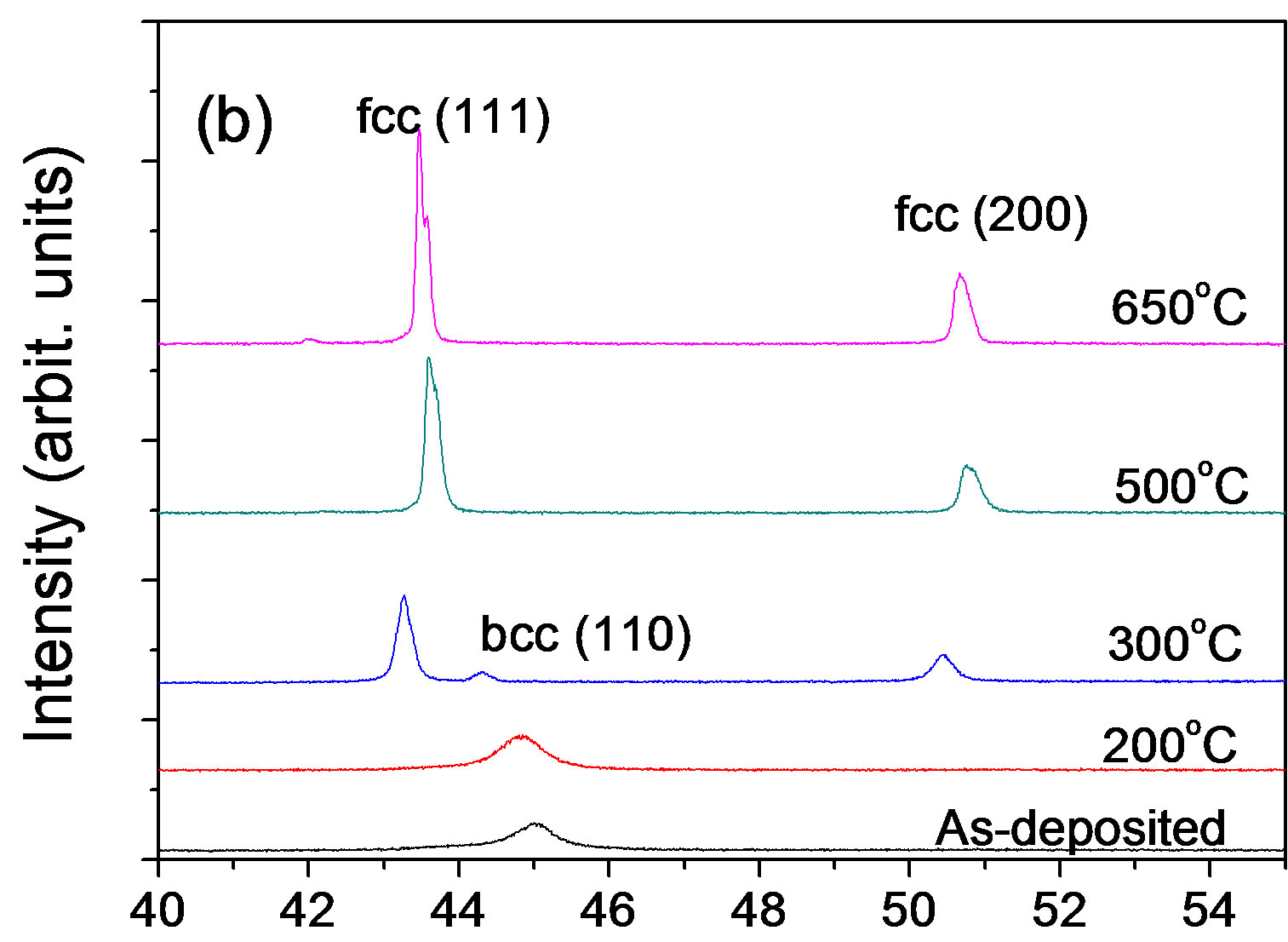 2θ (deg)
Figure 6. X-ray diffraction patterns for the (a) 65% Fe-Ni alloy and (b) 73% Fe-Ni alloy annealed at different temperatures.
occurred at 500˚C, when the alloy became ductile.
3.3. Representative Tensile Curves
Figure 7 shows the stress-strain curves of the Ni-65% Fe alloy as-deposited and annealed at 650˚C. The tensile strength is 995 MPa and 852 MPa for as-deposited and annealed at 650˚C, respectively. Different with the results of bend tests, these curves suggest the alloy as-deposited and annealed does not exhibit ductility. But the reason is unclear. However, four factors could affect the stressstrain curves: grain size, strain state, defects and thickness of these materials. For example, Li [14] demonstrated ductile-to-brittle transition in nanocrystalline metals by reducing grain size to their critical size (12 nm for the Ni-15% Fe alloy). Another example, Gu [28] found ductile-brittle-ductile transition in an electrodeposited 13 nanometer grain sized Ni-8.6 wt% Co alloy through increasing the strain rates from 1.04 × 10⁻⁵ to 1.04 s−1.
4. Conclusion
The phase of Ni100–xFex alloys in the as-deposited state is dependent on the iron content. A pure fcc phase is presented at low iron content (x < 55), a pure bcc phase at high iron content (x > 73), and fcc and bcc mixed phases
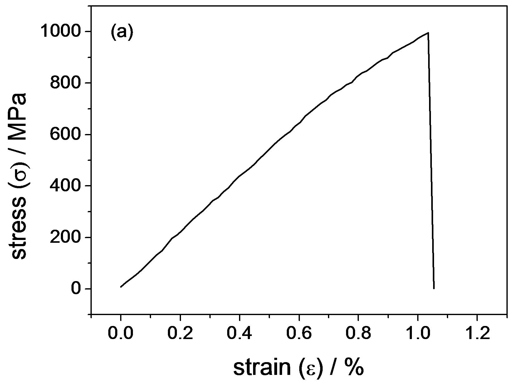
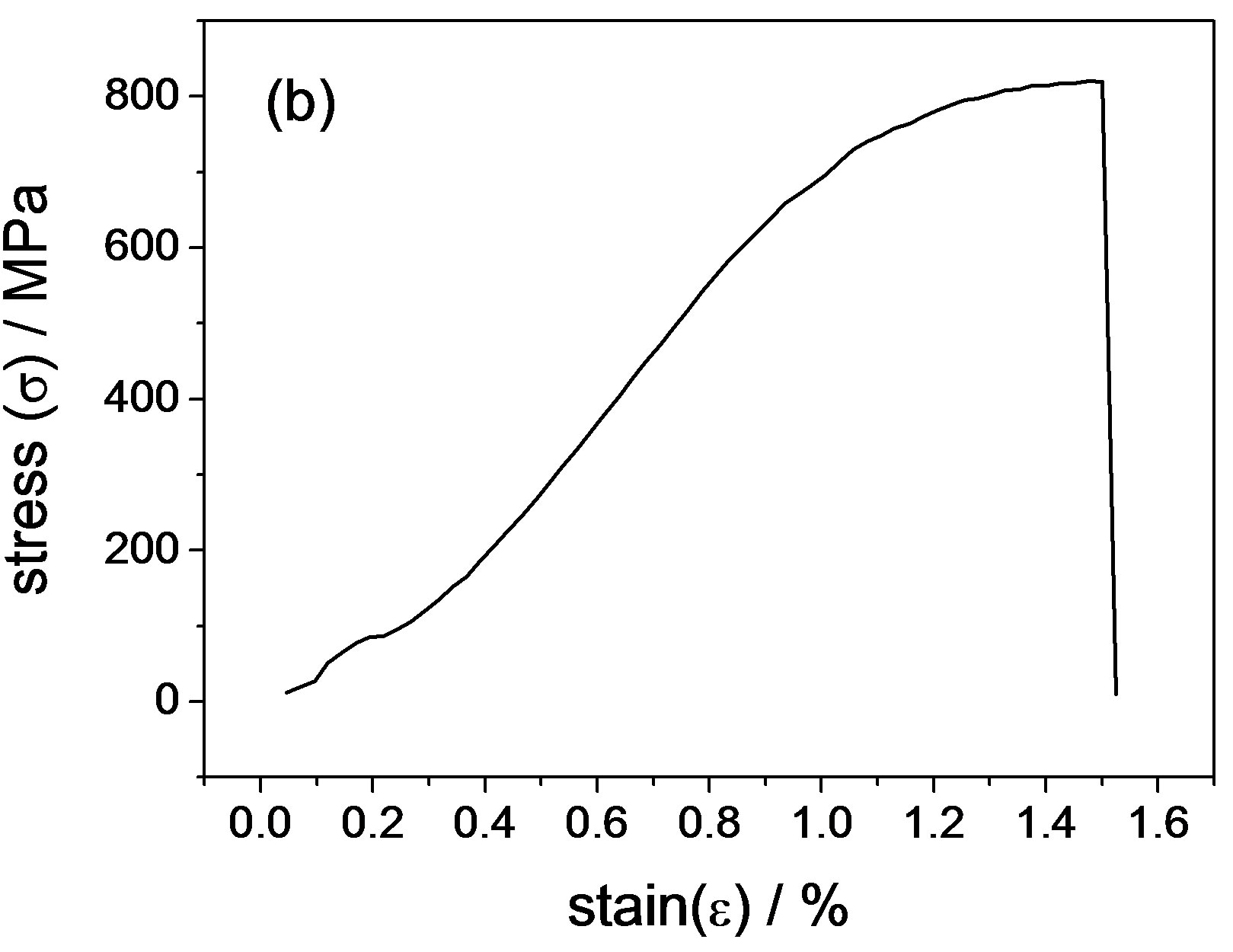
Figure 7. Stress–strain curves for electrodeposited Ni-65%Fe alloy (a) as-deposited and (b) annealed at 650˚C.
at middle iron content (55 < x < 73).
The ductile-brittle-ductile transformation occurred when Ni100–xFex alloys were annealed from room temperature to 650˚C. The embrittlement phenomenon arose from the sulfur segregation in grain boundaries. For Ni100–xFex alloys annealed at 200˚C, the ductility increased with the increase of iron content, indicating that iron can partly prevent the sulfur embrittlement, i.e. iron can improve thermal stability of Ni-Fe alloys. But nanocrystalline Ni-Fe alloys contained S impurity should be utilized only at a temperature of below 200˚C. Bcc to fcc phase transformation in the Ni100–xFex alloys (x > 55) was observed at the annealed temperature of over 300˚C.
5. Acknowledgements
This work was supported by Open Research Fund Program of Key Laboratory of Ethnic Medicine Resource Chemistry, State Ethnic Affairs Commission & Ministry of Education, Yunnan University of Nationalities, P.R. China (Fund Number: YMY1113), and supported by Program for Innovative Research Team (in Science and Technology) in University of Yunnan Province (IRTSTYN) and Green Chemistry and Functional Materials Research for Yunnan Innovation Team (2011HC008).
REFERENCES
- P. C. Andricacos, C. Arana, J. Tabib, J. Dukovic and L. T. Romankiw, “Electrodeposition of Nickel-Iron Alloys,” Journal of the Electrochemical Society, Vol. 136, No. 5, 1989, pp. 1136-1340. doi:10.1149/1.2096917
- D. L. Grimmett, M. Schwartz and K. Nobe, “Comparison of DC and Pulsed Fe-Ni Alloy Deposits,” Journal of the Electrochemical Society, Vol. 140, No. 4, 1993, pp. 1136- 1340. doi:10.1149/1.2056238
- C. Cheung, F. Djuanda, U. Erb and G. Palumbo, “Electrodeposition of Nanocrystalline Ni-Fe Alloys,” Nanostructured Materials, Vol. 5, No. 5, 1995, pp. 513-523. doi:10.1016/0965-9773(95)00264-F
- P. C. Andricacos and N. Robertson, “Future Directions in Electroplated Materials for Thin-Film Recording Heads,” IBM Journal of Research and Developement, Vol. 42, No. 5, 1998, pp. 671-680. doi:10.1147/rd.425.0671
- S. D. Leith, S. Ramli, D. T. Schwartz and J. Electrochem, “Characterization of NixFe1-x (0.10 < x < 0.95) ElectroDeposition from a Family of Sulfamate-Chloride Electrolytes,” Journal of the Electrochemical Society, Vol. 146, No. 4, 1999, pp. 1431-1435. doi:10.1149/1.1391781
- A. Afshar, A. G. Dolati and M. Ghorbani, “Electrochemical Characterization of the Ni-Fe Alloy Electrodepositon from Chloride-Citrate-Glycolic Acid Solutions,” Materials Chemistry and Physics, Vol. 72, No. 2, 2002, pp. 352-258.
- A. Ispas, H. Matsushima, W. Plieth and A. Bund, “Influence of a Magnetic Field on the Electrodeposition of NickelIron Alloys,” Electrochimica Acta, Vol. 52, No. 8, 2007, pp. 2785-2795. doi:10.1016/j.electacta.2006.10.064
- P. Fricoteaux and C. Rousse, “Influence of Substrate, pH and Magnetic Field onto Composition and Current Efficiency of Electrodeposited Ni-Fe Alloys,” Journal of Electroanalytical Chemistry, Vol. 612, No. 1, 2008, pp. 9-14. doi:10.1016/j.jelechem.2007.08.022
- H. Li and F. Ebrahimi, “Synthesis and Characterization of Electrodeposited Nanocrystalline Nickel-Iron Alloys,” Materials Science and Engineering: A, Vol. 347, No. 1-2, 2003, pp. 93-101. doi:10.1016/S0921-5093(02)00586-5
- F. Ebrahimi and H. Li, “Grain Growth In Electrodeposited Nanocrystalline Fcc Ni-Fe Alloys,” Scripta Materialia, Vol. 55, No. 3, 2006, pp. 263-366. doi:10.1016/j.scriptamat.2006.03.053
- F. R. Bento and L. H. Mascaro, “Electrocrystallisation of Fe-Ni Alloys from Chloride Electrolytes,” Surface and Coatings Technology, Vol. 201, No. 3-4, 2006, pp. 1752- 1756. doi:10.1016/j.surfcoat.2006.02.055
- F. Czerwinski, H. Li, M. Megret, J. A. Szpunar, D. G. Clark and U. Erb, “The Evolution of Texture and Grain Size During Annealing of Nanocrystalline Ni-45% Fe Electrodeposits,” Scripta Materialia, Vol. 37, No. 12, 1997, pp. 1967-1972. doi:10.1016/S1359-6462(97)00390-4
- H. Li and F. Ebrahimi, “An investigation of Thermal Stability and Microhardness of Electrodeposited Nanocrystalline Nickel-21% Iron Alloys,” Acta Materialia, Vol. 51, No. 13, 2003, pp. 3905-3913. doi:10.1016/S1359-6454(03)00215-5
- H. Li and F. Ebrahimi, “Ductile-to-Brittle Transition in Nanocrystalline Metals,” Advanced Materials, Vol. 17, No. 16, 2005, pp. 1969-1972. doi:10.1002/adma.200500436
- H. Li, P. K. Liaw, H. Choo, et al., “Temperature-Dependent Mechanical Behavior of a Nanostructured Ni-Fe Alloy,” Materials Science and Engineering: A, Vol. 493, No. 1-2, 2008, pp. 93-96. doi:10.1016/j.msea.2007.08.085
- H. Li and F. Ebrahimi, “Grain Growth in Electrodeposited Nanocrystalline Fcc Ni-Fe Alloys,” Scripta Materialia, Vol. 55, No. 3, 2006, pp. 263-366. doi:10.1016/j.scriptamat.2006.03.053
- I. Tabakovic, V. Intruri, J. Thurn and M. Kief, “Properties of Ni1−xFex (0.1 < x < 0.9) and Invar (x = 0.64) Alloys Obtained by Electrodeposition,” Electrochimica Acta, Vol. 55, No. 22, 2010, pp. 6749-6754. doi:10.1016/j.electacta.2010.05.095
- J. H. Seo, J. K. Kim, T. H. Yim and Y. B. Park, “Textrures and Grain Growth in Nanocrystalline Fe-Ni Alloys,” Materials Science Forum, Vol. 475-479, 2005, pp. 3483-3488. doi:10.4028/www.scientific.net/MSF.475-479.3483
- M. Thuvander, M. Abraham, A. Cerezo and G.D.W. Smith, “Thermal Stability of Electrodeposited Nanocrystalline Nickel and Iron-Nickel Alloys,” Materials Science and Technology, Vol. 17, No. 8, 2001, pp. 961-970. doi:10.1179/026708301101510799
- C. H. Huang, “Effect of Organic Additives on the Electroformed Nickel Alloys,” Metal Finishing, Vol. 91, No. 6, 1993, pp. 107-110.
- W. R. Wearmouth and K. C. Belt, “Electroforming with Heat-Resistant Sulfur-Hardened Nickel,” Pltating and Surface Finishing, Vol. 66, No. 10, 1979, pp. 53-57.
- C. H. Huang, J. R. Jan, W. Y Shu and H. M. Wu, “Study of Sulfur Embrittlement in Electroformed Ni-Re Alloy,” Journal of Materials Science, Vol. 36, No. 18, 2001, pp. 4385-4391. doi:10.1023/A:1017962215151
- C. W. Su, E. L. Wang, Y. B. Zhang and F. J. He, “Ni1−xFex (0.1 < x < 0.75) Alloy Foils Prepared From a Fluorborate Bath Using Electrochemical Deposition,” Jounal of Alloys and Compounds, Vol. 474, No. 1-2, 2009, pp. 190-194. doi:10.1016/j.jallcom.2008.06.050
- C. W. Su, F. J. He, H. Jui, Y. B. Zhang and E. L. Wang, “Electrodeposition of Ni, Fe and Ni-Fe Alloys on a 316 Stainless Steel Surface in a Fluorborate Bath,” Electrochimica Acta, Vol. 54, No. 26, 2009, pp. 6257-6263. doi:10.1016/j.electacta.2009.05.076
- J. W. Dini and H. R. Johnson, “The Influence of Nickel Sulfamate Operating Parameters on the Impurity Content and Properties of Electrodeposits,” Thin Solid Films, Vol. 54, No. 2, 1978, pp. 183-188. doi:10.1016/0040-6090(78)90197-9
- G. Cacciamani, A. Dinsdale, M. Palumbo and A. Pasturel, “The Fe-Ni System: Thermodynamic Modelling Assisted by Atomistic Calculations,” Intermetallics, Vol. 18, No. 6, 2010, pp. 1148-1162. doi:10.1016/j.intermet.2010.02.026
- A. K. Dokania, B. Kocdemir, R. Diebolder, J. Cai, R. J. Behm, R. Hibst and U. Herr, “α to γ Phase Transformation in Electrodeposited Invar Film by Short Pulse Laser Treatment,” Materials Science and Engineering: A, Vol. 456, No. 1, 2007, pp. 64-71. doi:10.1016/j.msea.2006.11.141
- C. Gu, J. Lian, Q. Jiang and Z. Jiang, “Ductile-Brittle-Ducitile Transition in an Electrodeposited 13 Nanometer Grain Sized Ni-8.6 wt% Co Alloy,” Materials Science and Engineering: A, Vol. 459, No. 1-2, 2007, pp. 75-81.