Open Journal of Composite Materials
Vol.4 No.2(2014), Article ID:44933,11 pages DOI:10.4236/ojcm.2014.42012
Optimum Design for CLD Laminate Plates Using Genetic Algorithms
Guang-Min Luo, Tsung-Yen Hsieh
Department of Naval Architecture and Ocean Engineering, National Kaohsiung Marine University, Kaohsiung, Taiwan
Email: gmluo@webmail.nkmu.edu.tw
Copyright © 2014 by authors and Scientific Research Publishing Inc.
This work is licensed under the Creative Commons Attribution International License (CC BY).
http://creativecommons.org/licenses/by/4.0/


Received 4 January 2014; revised 4 February 2014; accepted 28 February 2014
ABSTRACT
The optimizations of constrained layered damped (CLD) laminated structures are discussed in this study. Genetic algorithms (GAs) are employed as the search tool for optimization because these algorithms are suitable for solving optimization problems involving multiple discrete variable combinations. The numerical computation packages, ANSYS and MATLAB, have been used to estimate the optimum stacking sequence of CLD laminated structures. MATLAB package is used to achieve GAs process, and ANSYS package is used to proceed the structural analysis. This study successfully developed a numerical simulation mechanism for optimizing CLD adhesion efficiency by implementing GAs and the finite element method. The loss coefficients of the CLD damping layer vary with vibration frequency and failure constraints of CLD laminated plates are considered in objective function. In addition, the modified plasticity analysis (MPA) is used to increase the search efficiency of GAs and simply plastic analysis.
Keywords
Constrained Layered Damping (CLD), Genetic Algorithms (GAs)

1. Introduction
When fiber reinforced plastic (FRP) laminate structures are affected by an out-of-plane impact load, delamination frequently occurs due to a lack of interlaminar strength. In recent years, studies regarding how to enhance interlaminar strength have consistently emerged [1] -[3] . In particular, Luo applied constrained layered damping (CLD) to laminates and conducted low-velocity impact experiments and simulations, proving that CLD can effectively enhance the low-velocity impact strength of laminate structures [4] [5] .
CLD is a composite layer made from viscoelastic materials and thin metal. When a structure bends because of external pressure, the viscoelastic layer constrained within the metal layers produces shear deformation, consequently dissipating energy. Theoretically, the larger the amount of deformation is, the more effective CLD is when dissipating energy; however, excessive deformation may induce failure in the structure’s base material and the thin metal layers, thereby decreasing structural strength. Therefore, with consideration to the strength of laminate structures, the effectiveness of CLD adhesion can be enhanced by appropriately modifying stacking sequences, facilitating greater deformation capacity of the laminate structure within a reasonable range. This study adopted genetic algorithms (GAs) to examine the optimization of CLD laminate structures, in the hope of developing a numerical method to accurately search for optimal stacking sequences when external impacts occur, and ultimately maximizing the adhesion effects of CLD.
The strength of laminated materials is primarily determined by stacking sequence and angle. In recent years, numerous scholars have developed research on the optimization of laminate structures. A review of relevant studies is as follows:
Kere [6] adopted GAs to simulate the optimization of laminated cylindrical panels under various load conditions; Rao [7] employed scatter search algorithms to calculate the optimal stacking angles of laminates; Matsuzaki [8] adopted the fractal branch-and-bound method to optimize the stacking sequences for asymmetrical laminates; and Aymerich [9] adopted the ant-colony optimization method and identified the maximum value of buckling load by changing the stacking sequences of laminates.
Because stacking sequences and angles of laminated materials are regarded as combinations of multiple discrete variables, performing searches is more difficult when using traditional optimization methods. Hence, a majority of current studies have adopted GAs as a search tool for laminate optimization. For example, after accounting for structural stability, Nagendra [10] employed GAs to identify stacking sequence optimization; Rahul [11] proposed laminate optimization research on lateral impact and combined the finite element method with GAs to design inexpensive lightweight structures; and Antonio [12] contended that composite materials show nonlinear behavior and, consequently, used genetic manipulation to enhance overall search efficiency when optimizing stacking sequences. Moreover, Jafari [13] adopted GAs and finite element analysis to formulate a laminate structure optimization design, subsequently developing a mass-deflection or mass-cost minimization method before analyzing the maximum stiffness of the structures’ outer shells. Additionally, Narita [14] employed GAs and targeted staple fiber laminate structures with local anisotropism to conduct vibration optimization, successfully improving the effect of anisotropic staple fibers and achieving optimized designs.
This study adopted CLD adhesion efficiency in laminate structures as an objective for optimized design and searched for the most suitable stacking sequences when specific external forces were applied. This study employed GAs as the search tool for optimization because these algorithms are suitable for solving optimization problems involving multiple discrete variable combinations.
2. Methods
2.1. Introduction to Analysis
In this study, the ANSYS and MATLAB packages were combined to assess the optimization of CLD laminate structures. Specifically, the GA program was written using MATLAB, whereas structural strength was computed in ANSYS. In addition, the encoding and decoding method adopted in this study differed from those used in traditional GAs: encoding of differing stacking angles was conducted using a ranking method of 0 and 1. The codes and the corresponding stacking angles are shown in Table 1.
The procedures used in the study analysis were as follows: First, random genetic encoding was conducted in

Table 1. GA encoding of stacking angles.
MATLAB and the initial population was formed. Next, the codes were converted into their corresponding stacking angles, and structural strength calculations were conducted by inputting parametric design language into ANSYS. After completing structural analysis, data such as the amount of deformation, stress, and strain on the CLD laminate structures were extracted and substituted into MATLAB to compute the GA’s objective function and assess fitness values. Simultaneously, a single generation of GA computation was completed. The GA subsequently considered the fitness value outcomes and conducted processes including crossover and mutation, preserving the more optimal angle configurations to breed the next-generation population. Subsequently, the GA repeated computations regarding structural strength and the objective function until no objective functions demonstrating superior optimization levels could be obtained. Finally, the optimal solution was represented as the corresponding stacking angle. The procedures used in this study are shown in Figure 1.
2.2. Objective Function
This study assumed that when a CLD laminate structure is affected by an external impact, as the amount of deformation increases, adhesion becomes more effective. However, common optimization methods determine the minimum value of the objective function when locating optimal solutions. Therefore, when the amount of deformation for the CLD laminate structure reaches Δ, Objective function F can be shown as follows:
 (1)
(1)
Furthermore, to prevent the GA from searching for the optimal solution in a direction of extreme deformation, constraints must be implemented to control the search direction during optimization. When applying GAs to identify the optimal stacking sequence of laminates, constraints cannot be directly established on relevant parameters. Consequently, constraints must be written into the objective function. In this study, the constraints employed were the interlaminar strength of the laminated material, the tensile strength of the CLD, and the damping vibration frequency. The constraining method is described below:
1) Laminated Material Failure Constraint

Figure 1. Procedures of optimization.
Delamination is the most common type of failure that results from low-velocity impact. This study referred to the reciprocal stiffness degradation mechanism proposed by Huang [15] and adapted the delamination failure criteria proposed by Yeh, which adopt strain as a parameter, to serve as the failure constraint conditions:
Delamination failure from tension 
 (2)
(2)
Delamination failure from shear 
 (3)
(3)
where, 1, 2, and 3 represent fiber direction, perpendicular fiber direction, and thickness direction, respectively.  is the strength of tensile strain in the thickness direction,
  is the strength of shear strain on the Plane ij, εij is the principal strain in three directions represented on Plane ij, and γij is the shear strain on Plane ij.
f is the failure factor and represents the degree of failure. Failure begins when f = 1.0, and f > 1.0 indicates severe failure. The numerical definition is as follows:
 (4)
(4)
2) CLD Failure Constraint CLD is composed of damping material and thin metal. As identified in Luo [16] , damping failure occurs subsequent to thin metal failure when a material is affected by impact load. Consequently, when investigating CLD failure, only thin metal failure was considered.
The failure criteria proposed by Von Mises were adopted to form yield judgment criteria for the thin metal:
 (5)
(5)
 ,
,  , and
, and  represent principal stress in three directions. Assuming that
  is the yield stress for pure aluminum, its numerical definition may be defined as follows:
 (6)
(6)
3) Vibration Frequency The loss coefficients of the CLD damping layer vary with vibration frequency. This study employed 3M SJ- 2552 as the CLD material, with ISD-112 acting as the viscoelastic glue; the relationship between the vibration frequency of ISD-112 and damping is shown in Figure 2. The natural vibration frequency of the sample
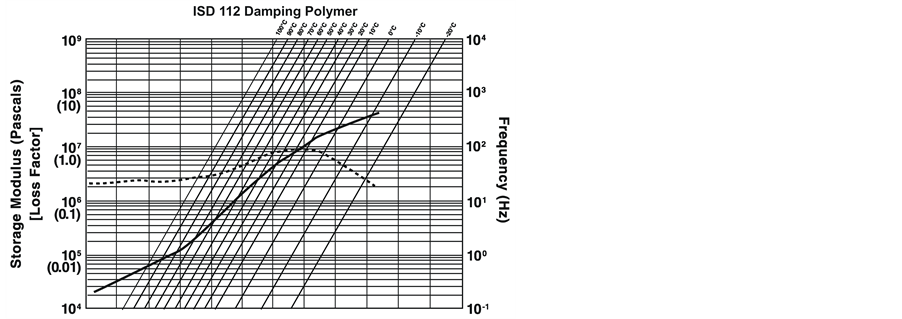
Figure 2. Loss factor of Damping Polymer ISD-112.
employed in this study varied depending on the stacking method, ranging between approximately 400 and 1000 Hz. Therefore, according to Figure 2, the variation in the relationship between Loss Factorη and Frequency ω can be delineated as follows:
 (7)
(7)
Moreover, the vibration frequency is represented as the following expression after conversion to numerical values:
 (8)
(8)
where, the  of 3M SJ-2552 is 0.9.
After establishing the quantified constraints, these constraints can then be employed to modify the initial objective function and to further accommodate the GA in its search for the optimal solution. The modified objective function was
 (9)
(9)
2.3. Modified Plasticity Analysis (MPA)
This study considered eight lamination angles, 0˚, ±30˚, ±45˚, ±60˚, and 90˚, to analyze laminar models with 16 layers and dimensions measuring 0.10 m long and 0.05 m wide. The laminated material was Toray T700/Epoxy E765, and the damping material for the constraint layer was 3M SJ-2552. Properties for related materials are shown in Table 2 and Table 3. During finite element simulation, the solid element, Solid 46, was used to simulate the laminar structure, whereas Solid 45 was employed to simulate the damping material and aluminum sheet. Boundary conditions were fixed at both ends.
Table 2. Material properties of Toray T700/Epoxy E765.
Table 3. Material properties of 3M SJ-2552.
ANSYS typically conducts simplified plastic analysis and frequently assumes that the elastic-plastic behavior of a material implies a bilinear stress-strain relationship; however, computation using ANSYS is highly timeconsuming. To increase the search efficiency of the GA, this study modified aluminum plasticity stress in MATLAB rather than performing this procedure in ANSYS, and titled the process “modified plasticity analysis” (MPA). The analysis method is described below:
The bilinear stress-strain relationship of the aluminum yield was first written into MATLAB, and ANSYS was implemented to perform only linear elasticity analysis. The bilinear stress-strain relationship of the aluminum yield is shown in Figure 3.
In Figure 3, Point A shows the yield stress of the material, m1 is the coefficient of elasticity for aluminum, and m2 is the coefficient of elasticity beyond the aluminum yield point. The aluminum stress value was retrieved during each generational computation to determine if it had exceeded the yield stress point. If the aluminum stress had not yet reached the yield stress point, no modification was required. If the aluminum stress had exceeded the yield stress point, it was automatically converted into a stress value corresponding to the m2 curve and substituted into Equations (5) and (6) to solve for parameter CFC. If MPA was proven feasible, it could reduce the time required for performing plasticity analysis using ANSYS as well as significantly improve computational efficiency.
The testing case of MPA was titled “M-Plas-01” and normal plasticity analysis of ANSYS was titled “Plas-01”. Subsequently, the results of both methods were compared to verify the accuracy of MPA.
In Table 4, computational results derived from comparisons of Plas-01 and M-Plas-01 regarding factors such as the amount of deformation in the CLD laminar structure and aluminum stress suggest an error value of less than 5%. This demonstrated that M-Plas-01 possessed a significant level of precision during analysis. Furthermore, in the search for optimal solutions, the computation time required for M-Plas-01 was significantly shorter than that necessary for Plas-01, facilitating the completion of computations in half the time required for traditional methods. Consequently, M-Plas-01 demonstrated higher efficiency.
Based on these test results, traditional plasticity analysis was replaced with the proposed modified plasticity analysis in subsequent optimization computations to further reduce computation time.
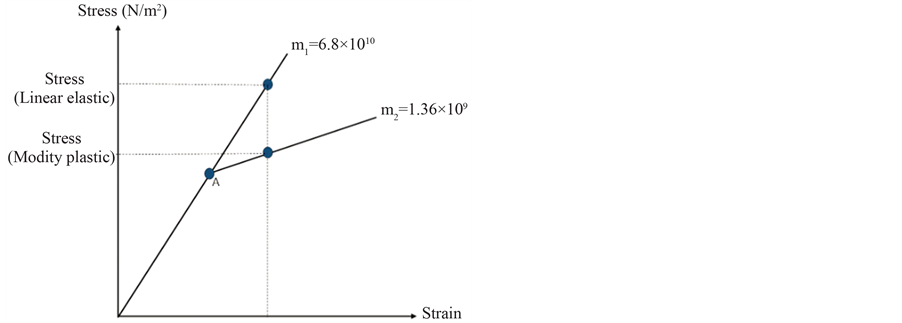
Figure 3. The bilinear stress-strain relationship of aluminum.
Table 4. Analysis results of Plas-01 and M-Plas-01.
3. Optimization Parameters
When assigning parameters for optimization, varying genetic parameters may affect the convergence and accuracy of numerical analysis. Therefore, a uniform static load of 105 N/m2 was initially employed to determine appropriate genetic parameters, which then served as a reference when identifying the optimal solution for dynamic load.
The parameters considered in this study included population size, number of genes, crossover rate, mutation rate, and elitism. Subsequently, each parameter was adjusted and modified to facilitate comparisons of the computation results and the time required to complete computations.
The order of parameter modifications was as follows: no crossover rate (Cros-off), high crossover rate (Croshigh), no mutation rate (Mut-off), high mutation rate (Mut-high), small population size (Popu-less), large population size (Popu-high), small generation size (Gen-less), large generation size (Gen-high), and no elitism (Eli-off). The assignment of parameter values is shown in Table 5.
The computation results for the parameters are shown in Table 6. Comparisons between the target functions and time demonstrated that Cros-high, Mut-off, and Mut-high possessed significant search efficiency. However, parameter assignment for Mut-off was not adopted because Mut-off implied that no mutation rate was set, and an assumption of no mutation rate could result in a partial optimal solution. Furthermore, optimal solutions can be obtained when fewer generations of Mut-high are employed; consequently, the Mut-high assigning mode was adopted in subsequent dynamic simulations to increase efficiency when identifying optimal solutions.
Table 5. Assignment of gene parameter values.
Table 6. Computation results for disparate gene parameters.
4. Discussions
This study primarily endeavored to investigate the structural optimization of CLD laminar structure when affected by low-velocity impact. The low-velocity impact conditions were simulated using dynamic uniform loadings and assuming that impact duration (Δ) of uniform loadings were 0.01 s and 0.02 s individually. Additionally, uniform loadings were postulated to impact at a half sine-wave, with maximum values of impact force (Pmax) were 500 N and 1000 N. Types of external force are shown in Figure 4.
Structural strength and stiffness can be determined using the stacking sequence of a laminate. Therefore, when the deformation of a laminate increases or when the laminate is located in a certain vibration frequency range, the damping layer can demonstrate larger shear deformation or a higher loss factor, both of which would affect CLD adhesion efficiency. Thus, the optimization objective for this study was to adequately modify stacking angles so that an appropriate amount of deformation in the laminate was produced when it was affected by an equivalent load.
During simulation, modal analysis was initially conducted to identify the natural vibration frequency of the CLD laminar structure, thereby allowing the computation of parameter VF in the objective function. A dynamic impact simulation was subsequently conducted and the maximum values of the amount of deformation, stress, and strain for the CLD laminar structure were computed; these values varied with time. The values of the calculated stress and strain could be used to compute the LFC and CFC values in the objective function, and the amount of deformation was represented as Δ in the objective function.
Subsequently, the damping thickness was modified and adopted as a genetic variable. Damping thickness was entered into the GA with the stacking angle variable to assess and observe if adhesion efficiency improved after modifying both factors. In the present study, the dynamic analysis of constant damping thickness was titled “Opt-n” and varying damping thickness was titled “Opt-n-d”. The code n was 1 to 4, and it represented various impact loading conditions respectively. The assignment of genetic parameters for Opt-n-d was identical to that for Opt-n, in which damping thickness was constrained between 0.1 mm and 1.0 mm. After computation, the parameters of Opt-n and Opt-n-d, such as the objective function and the amount of deformation, were compared, and this comparison was adopted to assess whether significant variation occurred in adhesion efficiency due to modifications in damping thickness. Nomenclature of different loading conditions was shown in Table 7.
The computation results for low-velocity impact optimization are shown in Tables 7-10. In this study, Opt-1 and Opt-1-d are utilized to illustrate the computation results first, and the search and retrieval processes employed for the GA are shown in Figure 5.
Table 8 shows the computation results of comparisons between Opt-1 and Opt-1-d. A discussion regarding the Opt-1 and Opt-1-d results derived from the objective function and relevant deformation amounts is included below:

Figure 4. Half-sine wave loading.
Table 7. Nomenclature of various impact loading conditions.
*, “-d” means damping thickness is a varying parameter.
Table 8. Comparison results of Opt-1 and Opt-1-d.
Table 9. Comparison results of Opt-2 and Opt-2-d.
Table 10. Comparison results of Opt-3 and Opt-3-d.

Figure 5. The retrieval processes of Opt-1/Opt-1-d.
First, as the objective function decreases, the adhesion efficiency identified during the GA search increases. Table 7 indicates that the objective functions of Opt-1-d, 1.2472, is slightly smaller than that of Opt-1, thereby proving that modifying damping thickness is effective in improving CLD adhesion efficiency.
In addition, computations for Opt-1-d suggested that only 2.6 mm of deformation was required to achieve optimal CLD adhesion efficiency. This amount was 16.13% less than that computed using Opt-1, which was equivalent to 3.1 mm. This phenomenon confirms that increasing the amount of deformation is not the only method that can be adopted to improve CLD adhesion efficiency and that results of more substantial significance are observed by appropriately increasing damping thickness. However, the computation results also indicate that increasing damping thickness is not necessarily a superior method for optimization, and optimal effects were only produced when the increase in damping thickness was complemented by stacking sequences for the laminated material. This data confirms the necessity of structural optimization.
Finally, regarding damping thickness, the comparison in Table 8 demonstrates that the thickness determined using Opt-1-d was 0.882 mm, which was much larger than the damping layer thickness of 0.127 mm for 3 M SJ-2552. However, the density of the damping material was one-third that of the laminated material. Based on the density of typical laminar structures, this degree of variation in damping thickness should not significantly affect the mass of the overall structure. As indicated by Table 8, appropriately increasing the thickness of the damping layer can reduce structural deformation amounts from 3.1 mm to 2.6 mm under the preliminary condition that similar damping adhesion efficiencies are present. This verifies that increasing damping thickness can maintain optimal adhesion efficiency as well as effectively reduce the amount of deformation in the laminar structure, thereby decreasing the probability of structural failure. Furthermore, the difference in vibration frequency was less than 1%, suggesting that this type of damping possessed a higher energy absorption capacity within the proposed vibration frequency range.
The other three kinds of computation results have the same conclusion as Opt-1 and Opt-1-d presented. The details were shown in Tables 9-11.
Based on the above results, it is evident that this study has successfully employed GAs to evaluate an appropriate stacking angle arrangement, resulting in optimal efficiency when CLD is adhered to laminates.
5. Conclusions
This study successfully developed a numerical simulation mechanism for optimizing CLD adhesion efficiency by implementing GAs and the finite element method. In addition, appropriately modifying damping thickness had evident benefits concerning enhancements in adhesion efficiency. The methods implemented and conclusions drawn from the simulation analyses conducted in this study are summarized below:
1) MATLAB and ANSYS were successfully integrated to examine the optimization of CLD adhesion efficiency when affected by impacts resulting from specific external forces. Future research can adapt the modal investigation employed in this study to explore the optimal effects of CLD adhesion and the optimal stacking angle arrangement when affected by different external force loads.
2) The modified plasticity analysis (MPA) method, in which stress modification beyond the aluminum yield point is written directly into MATLAB, was proposed. Consequently, finite element analysis required only linear elasticity computations, which effectively reduced the time traditionally required to conduct plasticity analysis using ANSYS and substantially improved speed when searching for optimal solutions.
3) This study confirmed that appropriately modifying both stacking angles and damping thicknesses are beneficial to improve the efficiency of CLD adhesion to laminates. In particular, increasing damping thickness can result in optimal adhesion efficiency in the case of a smaller amount of deformation, thereby enhancing structural stability.
Table 11. Comparison results of Opt-4 and Opt-4-d. Acknowledgements The authors would like to thank the National Science Council of the Republic of China for financially supporting this research. References