Open Journal of Composite Materials
Vol.4 No.1(2014), Article ID:41971,10 pages DOI:10.4236/ojcm.2014.41003
Electrical Resistance Change of Carbon/Epoxy Composite Laminates under Cyclic Loading under Damage Initiation Limit
![]()
Department of Mechanical Sciences and Engineering, Tokyo Institute of Technology, Tokyo, Japan.
Email: *atodorok@ginza.mes.titech.ac.jp
Copyright © 2014 Akira Todoroki et al. This is an open access article distributed under the Creative Commons Attribution License, which permits unrestricted use, distribution, and reproduction in any medium, provided the original work is properly cited. In accordance of the Creative Commons Attribution License all Copyrights © 2014 are reserved for SCIRP and the owner of the intellectual property Akira Todoroki et al. All Copyright © 2014 are guarded by law and by SCIRP as a guardian.
Received November 8th, 2013; revised December 8th, 2013; accepted December 25th, 2013
KEYWORDS
Carbon Fiber; Electrical Properties; Non-Destructive Testing; Smart Materials
ABSTRACT
Self-sensing multifunctional composite has sensing function using electrical resistance changes. Carbon Fiber Reinforced Polymer (CFRP) composite is one of the self-sensing multifunctional composites. For the reliability of the self-sensing, electrical contact between the lead wire and the carbon fibers is the most important issue. The present study focuses on the effect of the cyclic loading of lower applied strain range than the fatigue damage level. As a result, the electrical contact resistance at the copper electrode increased with the increase of cycles. That means that the electrical change at the electrodes must be considered for the long-term self-sensing monitoring system. When a four-probe method is used to measure the electrical resistance, the contact resistance effect is minimized. Moreover, angle-ply laminates have plastic deformation caused by shear loading, and that causes electrical resistance decrease during the cyclic loading. Cross-ply laminates of CFRP composites have no electrical resistance increase without damage. Quasi-isotropic laminates of CFRP composites, however, have electrical resistance decrease with the increase of the number of cycles because of the plastic deformation of the angle-ply laminates.
1. Introduction
Carbon Fiber Reinforced Polymer (CFRP) is applied to aerospace structures and automobile structures because of its light weight, high strength and high stiffness. A delamination crack of a CFRP laminated structure is, however, quite difficult to detect for visual inspection. That causes the requirement of self-sensing CFRP structures: the self-sensing CFRP uses the reinforcement carbon fibers as sensors [1-22]. The method detects the defects from the electrical resistance change of the CFRP structure.
Schulte et al. [1] measured electrical resistance changes of the coupon specimens during tensile tests using a twoprobe method: two electrical probes are made at the both ends of the specimen. Wang and Chung [4] adopted a four-probe method to remove the electrical contact resistance at electrodes: the outer couple of electrodes is used to apply electric current and the inner couple of electrodes is used to measure electrical voltage change. Irving et al. [6] and Seo et al. [7] employed the self-sensing method to detect fatigue damage of the unidirectional CFRP and cross-ply CFRP. De Baere et al. [15] used the self-sensing method for fatigue damage detection of woven fabric CFRP composites.
Todoroki et al. [18] adopted copper electric plating to make electrodes on CFRP specimens and performed cyclic loading tests up to 100 cycles. The results experimentally showed that the copper plating electrodes did not have degradation at least up to the 100 cycles. In that study, although electrical resistance changes decrease until 105 cycles, the experimental results included the effect of the temperature change and the effects were not separated from the effect of cyclic loading. For the selfsensing method, the most important issue is the reliability of the electrodes. To confirm the reliability of the electrodes, temperature change effect must be distinguished during the cyclic loading tests because the temperature change surely occurs during the cyclic loading process of actual composite structures. The published papers dealt with the fatigue damage detection using the electrical resistance changes. The electrical resistance change during cyclic loading without damage is not dealt with.
In the present study, at first, a temperature compensation method is shown to distinguish the effect of the temperature change from the long term cyclic loading test. A new three-probe method is proposed here to measure change of electric contact resistance at an electrode: the three-probe method is an improved method made from the four-probe method. Low cyclic strain is applied here to prevent fatigue damages. The electrical resistance change is measured under the low applied strain without damages.
2. Experimental Method
2.1. Materials
The material used in the experiments is unidirectional prepreg sheet (Mitsubishi Rayon Japan, PYROFIL#380). The stacking sequences are quasi-isotropic [0/45/-45/90]S and cross-ply [02/902]s. Plates of 250 mm length and 150 mm width of 1.7 mm thickness were made using an autoclave.
The pre-cure condition was 85˚C × 2 hours, and the main curing condition was 135˚C × 3 hours under 0.7 MPa pressure. After the curing, fiber volume fraction Vf was measured with the resin burn-off method, and the measured Vf was 67%. From the CFRP plates, rectangular plate specimens of 230 mm length and 12.5 mm width were produced as shown in Figure 1. On one side of the specimen surface, four copper electrodes of 5 mm width were made using the copper plating method described in the reference [18]. After making the electrodes, to prevent the effect of moisture absorption, the specimens were kept in a muffle furnace at 50˚C during 20 hours.
To measure the electrical resistance of the specimen,
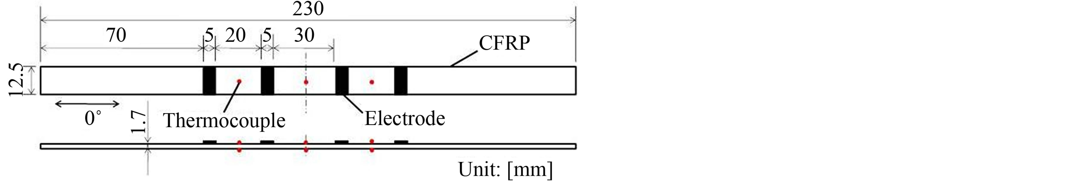
Figure 1. Specimen configuration.
the four-probe method is adopted here and a LCR meter #3522 made by Hioki Co. Japan is used. For the measurements, alternating current of 450 Hz of 30 mA is applied, and the impedance using the alternating current is measured. As the phase angle of the measured impedances of the alternating current were zero, the measured impedance was considered to be an electrical resistance here. To measure the electrical contact resistance at the electrode, a newly developed three-probe method was applied here. The three-probe method is described in the later section. The single specimen side surface was polished and the damage between the electrodes was observed here.
2.2. Temperature Compensation Experiments
To obtain electrical resistance changes caused by temperature change, a hot plate and a cooler box were prepared. K-type thermo-couples were used to measure temperature of the specimen. At the middle between the electrodes, the K-type thermo-couples were mounted shown as dots in Figure 1. The measured temperature range was from −30˚C to 70˚C. The highest temperature 70˚C of the test is lower than the temperature limit 90˚C of the CFRP used here. To prevent temperature distribution, the specimen was covered with glass-wool heat-insulation material, and the variation of the measured temperature of six points was kept within ±1˚C. The reference temperature of the specimen is the averaged temperature. Under this stable condition, the relationship between the temperature and the electrical resistance change ratio ΔR/R0 was measured for the temperature compensation. As a reference value of the electrical resistance R0, the electrical resistance at 20˚C is employed here.
2.3. Measurement of Electrical Contact Resistance
The four-probe method is shown in Figure 1: the outer couple of electrodes (A and D) were used to apply electric current and the inner couple of electrodes (B and C) were used to measure electric voltage. When the electrical resistance of the voltage meter is fully high (such as order of MΩ), the electrical current flowing in the voltage meter is negligibly small because the electrical resistance of the specimen is less than 1 Ω. This enables us to measure the electrical resistance independent of the electrode contact resistance using the four-probe method.
In the present study, at first, the electrical resistance of the specimen (R) is measured with the four-probe method. After that, the four-probe circuit is switched to the threeprobe circuit as shown in Figure 2. The three-probe method includes the electrical contact resistance (r) at the electrode B. The measured electrical resistance with the three-probe method is, therefore, (R + r). Subtraction of (R) from the (R + r) gives the electrical contact resistance (r). The method enables us to measure both (R) and (r) using a relay switch circuit. All measured electrical resistance changes ΔR (=R − R0: R0 is a reference electrical resistance at 103 cycles here) are normalized by R0 to delete the difference of the electrical resistance of each specimen.
2.4. Cyclic Loading Test
For the cyclic loading test, a closed-loop hydrostaticservo material-testing machine is used. Tension-tension cyclic loading tests of stress ratio R = 0.1 are performed here. The applied maximum strain for the quasi-isotropic specimen is 2800 μ that is only 20% of the tensile fracture strain (fracture stress is 695 MPa). The frequency is 50 Hz and the sine wave is used for loading. The maximum number of cycles is 106 here.
The reason why the applied strain is set to 20% of the fracture strain is as follows. For the actual aircraft design, the most important criterion is the compression-after-impact strength, and this demands the limitation load of 20% - 30% of the compression strength. Generally, the compression strength is almost equal to the 70% of the tensile strength. This indicates that the 20% of the tensile load is approximately used as the maximum applied load for the actual composite structures. The cyclic loading strain of the cross-ply laminate is also set to this. Most of the electric current flows in the surface 0˚-plies for both types of the specimens. As the electrical resistance change is mainly controlled by the applied strain as shown in the reference [17], this equal applied strain shows almost similar electrical resistance change under the no-damage loading condition. In the present study, therefore, the applied tensile strain is kept at the same value for the both types of the laminates.
To measure electrical resistance change, a LCR meter (type 3522) produced by Hioki Co. Japan was used. For the measurements, alternating current of 450 Hz and 30 mA was adopted, and the impedance changes were measured. As the phase angles of the measured impedances were all 0, the measured impedances were treated as being equal to electrical resistances in the present study.
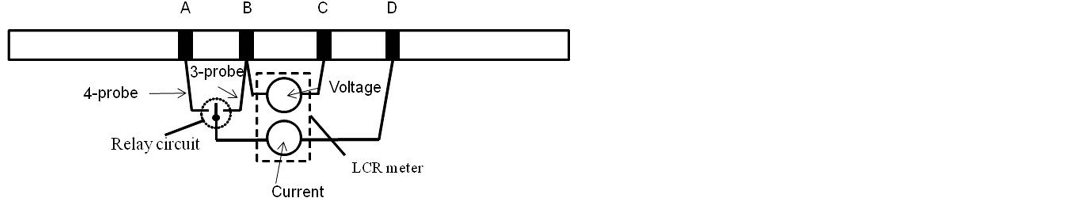
Figure 2. Schema of three-probe method to measure contact resistance.
For the measurement of the electrical resistance changes of the specimen, the four-probe method was used and the three-probe method was used to measure the electrical contact resistance change at electrode. Using a micro computer, switching from the four-probe to the three-probe method was performed with the interval of 40 s. This enables us to measure the electrical resistance changes of the CFRP and electrical contact resistance changes automatically. To measure the applied strain and residual strain under the completely unloaded condition, a normal type two-axis strain gage is used here. Six thermo couples were used to measure the temperature change and the reference temperature is decided at the mean applied load by averaging the six temperature values. The obtained experimental results are all transferred to the data at 20˚C using the temperature compensation. The specimen side surface was observed in situ during the cyclic loading using a video microscope.
3. Experimental Results and Discussion
3.1. Temperature Compensation
Figure 3 shows the typical electric resistance change ratio during temperature changing tests. The abscissa is the average temperature calculated from the six thermo couples. The ordinate is the electrical resistance change from the reference electrical resistance at 20˚C normalized by the reference resistance. Three tests were performed here. During the tests, the temperature deviation was kept within ±1˚C. As shown in Figure 3, the variation of the normalized electrical resistance ratio of the three-test results is very small, and the electrical resistance change caused by the temperature change is linear as follows.
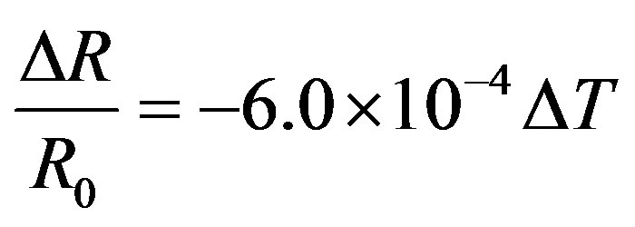 (1)
(1)
The electrical resistance change caused by temperature change has the linear relationship. Using the linear rela-
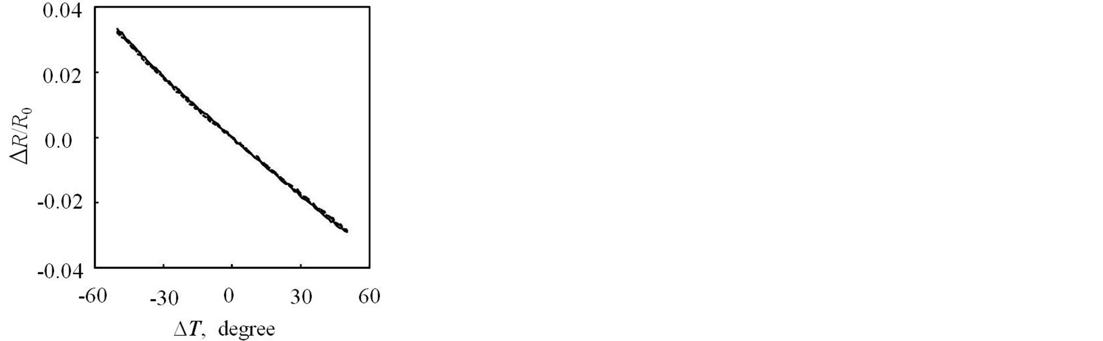
Figure 3. Temperature change effect of electrical resistance change ratio of quasi-isotropic CFRP laminate.
tionship, the specimen electrical resistance can be compensated against the temperature change when the temperature distribution is measured. The electrical resistance of a CFRP specimen depends on the temperature, the damage, the applied strain and the degree of water absorption. In the present test, the specimen has no damage as well as no moisture absorption. The electrical resistance change due to applied strain in small applied load is linear relationship [23]. This means that the electrical resistance change caused by the temperature change can be independently compensated with the measurement of temperature distribution of the specimen. As the temperature difference in the specimen is small in the present study, the temperature distribution can be assumed to be linear. This easily gives the mean temperature. As shown in the Figure 3, the electrical resistance change linearly decreases with the increase of the temperature. The temperature compensation of the electrical resistance change can be applied though the gage length of the specimen. The compensation easily gives the electrical resistance change at 20˚C.
Figure 4 shows the measured temperature change during the cyclic loading test. As shown in Figure 4, the temperature change during the cyclic loading is within 2˚C. The small temperature change affect electrical resistance change of order of 10−3. The measured electrical resistance changes shown in the later section are all compensated to the electrical resistance at 20˚C using the Equation (1), and the effect of the temperature change is completely deleted.
Figure 5 shows the temperature compensated results compared with the results without compensations. The triangular symbols show the results without temperature compensations and the circle symbols show the results with temperature compensations. As shown here, the effect of the temperature compensation is very small in the present study. That is because of the temperature retain-
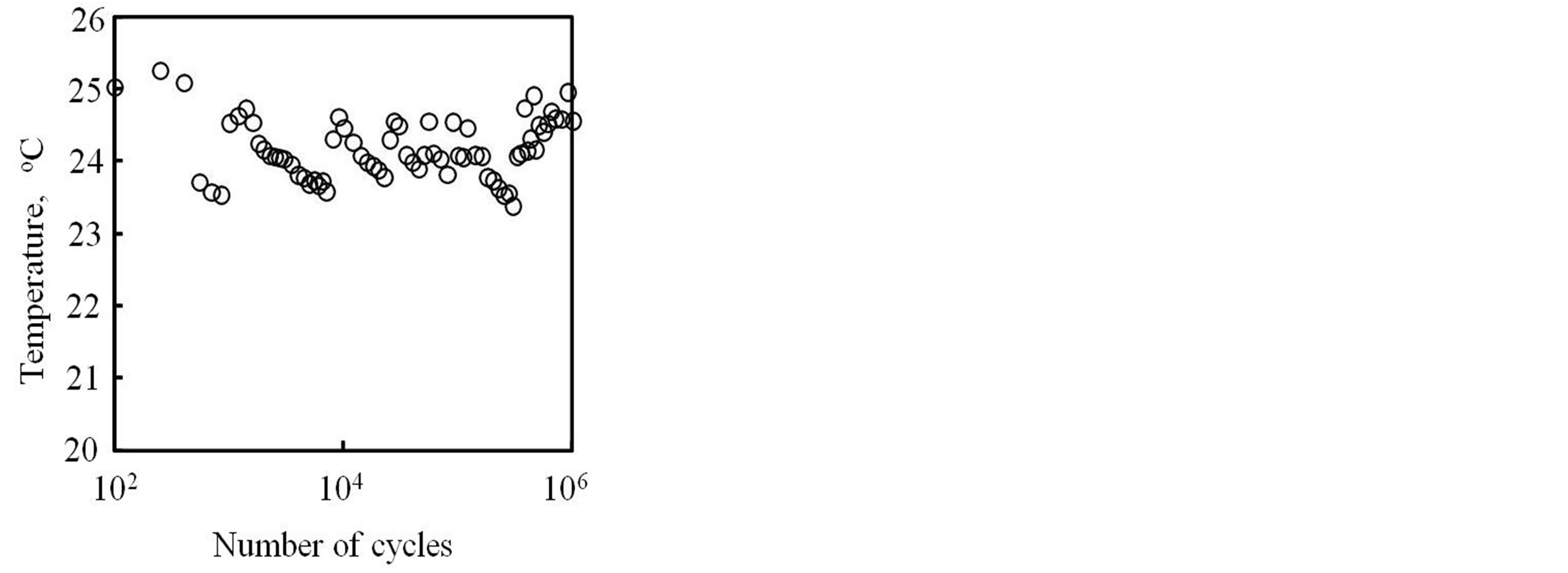
Figure 4. Measured temperature change of quasi-isotropic CFRP laminate during cyclic loading test.
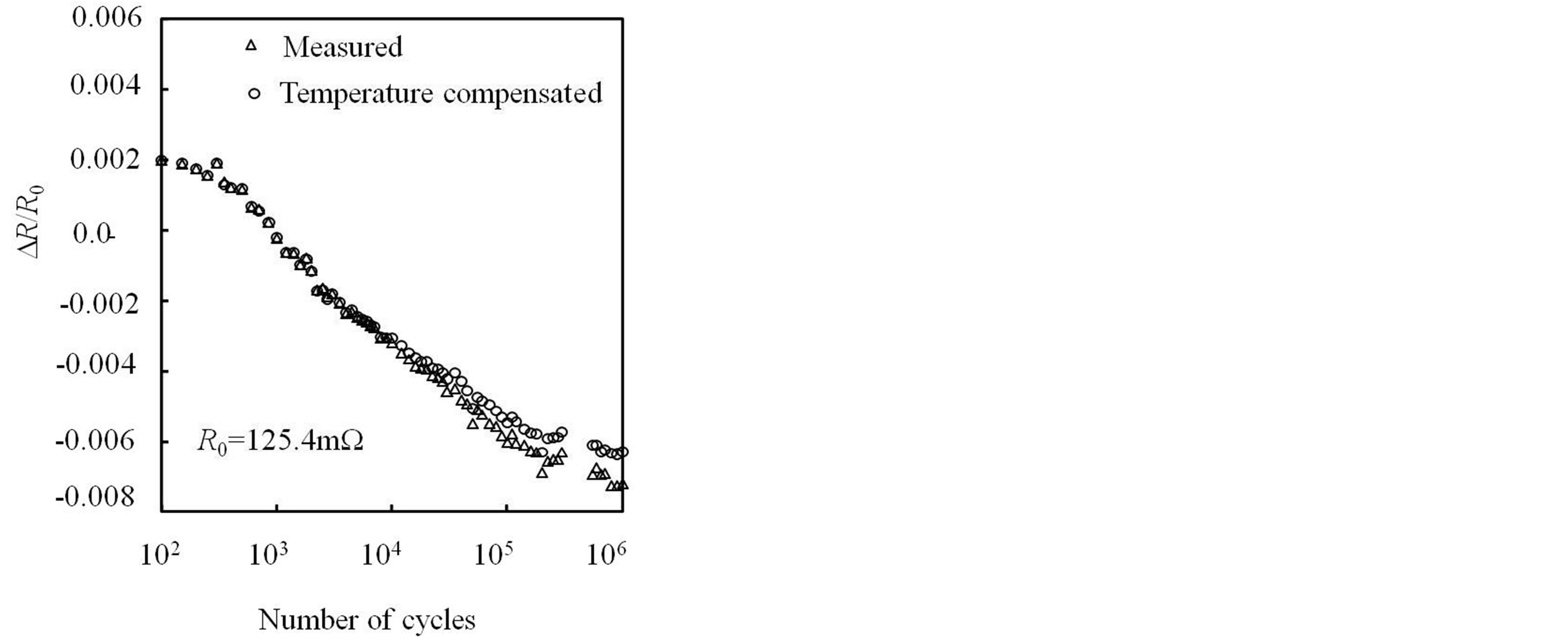
Figure 5. Effect of the temperature compensation of the isotropic laminate.
ing measures such as glass wool and using an air condition during cyclic loading tests. The temperature compensation, however, is important for the condition of large temperature change in the actual CFRP structures.
3.2. Electrical Resistance Change during Cyclic Loading
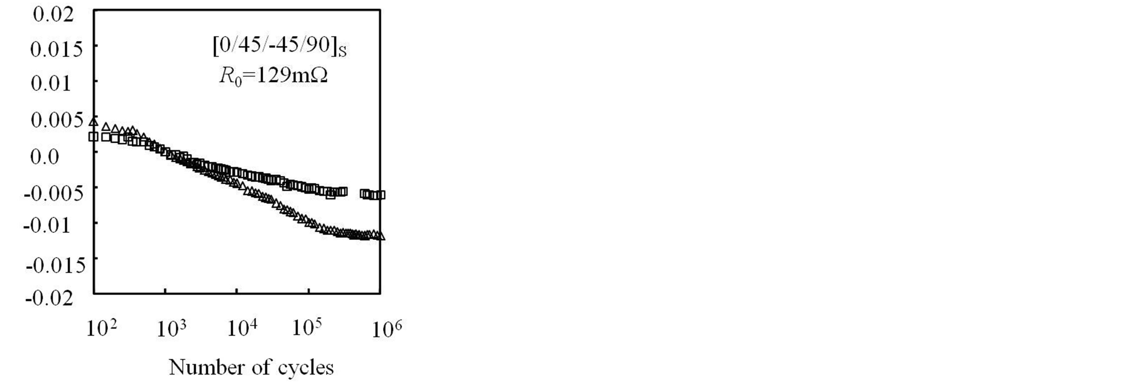
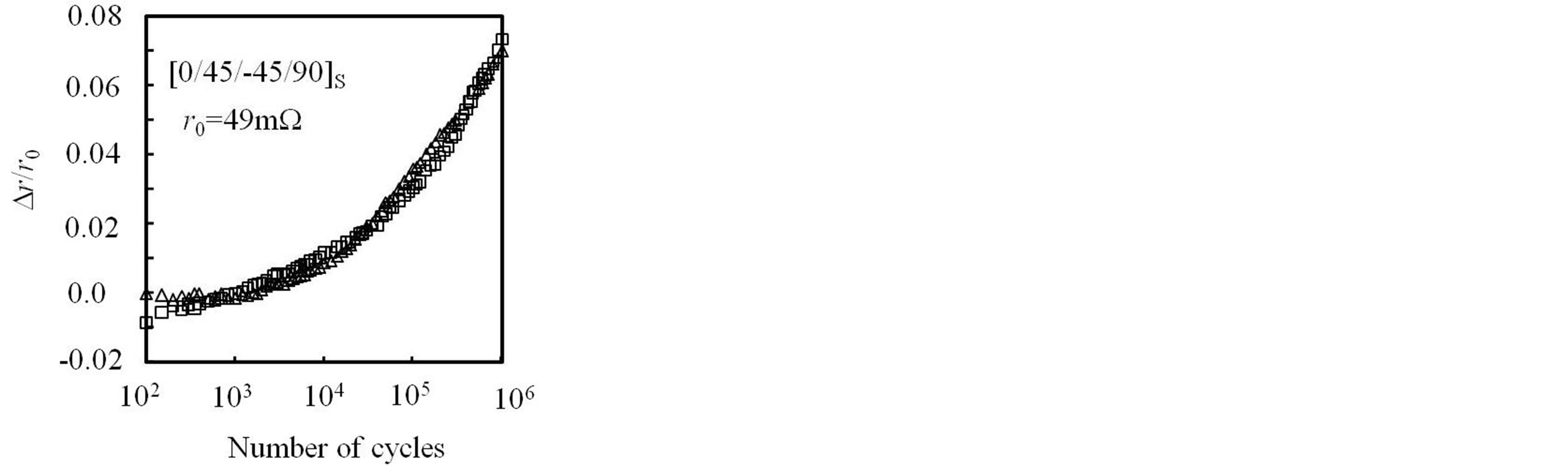
Figures 6(a) and (b) show the electrical resistance change of the quasi-isotropic and the cross-ply laminates during cyclic loading. The abscissa is the number of cycles and the ordinate is the electrical resistance change ratio using the reference resistance at 103 cycles and 20˚C. Two specimens were tested and both showed similar results. As mentioned before, the maximum strain of the cyclic loading is 20% of the fracture strain. After the cyclic loading up to 106 cycles, the polished specimen side surface was carefully observed using a video-microscope. As shown in Figure 7, no damage is found. This means that the electrical resistance decrease observed in the early cycles of Figure 6 is not caused by the damage during cyclic loading. The electrical resistance of the quasi-isotropic laminate decreases with the increase of the cyclic loading as shown in Figures 5 and 6(a), and the electrical resistance of the cross-ply laminate shows almost no change as shown in Figure 6(b) as the same as the results of the reference [24] before matrix cracking.
Figures 8(a) and (b) shows the results of the electrical contact resistance at electrodes measured with the threeprobe method. The abscissa is the number of cycles and the ordinate is the measured electrical contact resistance at electrodes. Figures 8(a) and (b) show the results of the two specimens. Two specimens were tested and the similar results were obtained.
In both laminates, rapid increase of the electrical contact resistance is observed over 105 cycles. This indicates
 (a) Quasi-isotropic laminate
 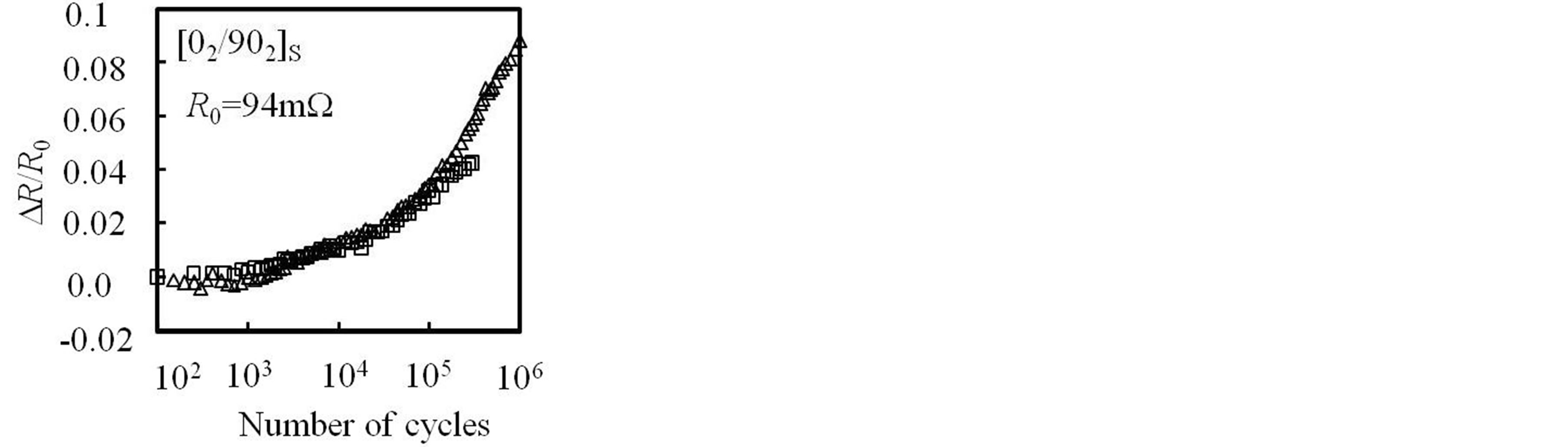 (b) Cross-ply laminate
Figure 6. Measured electrical resistance change ratio during cyclic loading test.
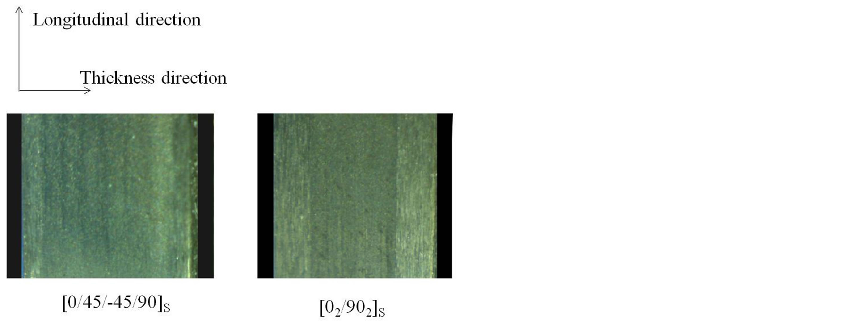
Figure 7. Lateral side surface observation.
that the electrical contact damage caused by cyclic loading affect the electrical contact resistance over 105 cycles even if the copper plating electrodes are used. As shown in Figure 6, the measured electrical resistance with the four-probe method shows no rapid increase. This means the four-probe method is very robust against the electrical contact resistance change at electrodes. The both electrical contact resistance changes in Figures 8(a) and (b) are the results of the copper plating electrodes made on
 (a) Quasi-isotropic laminate
 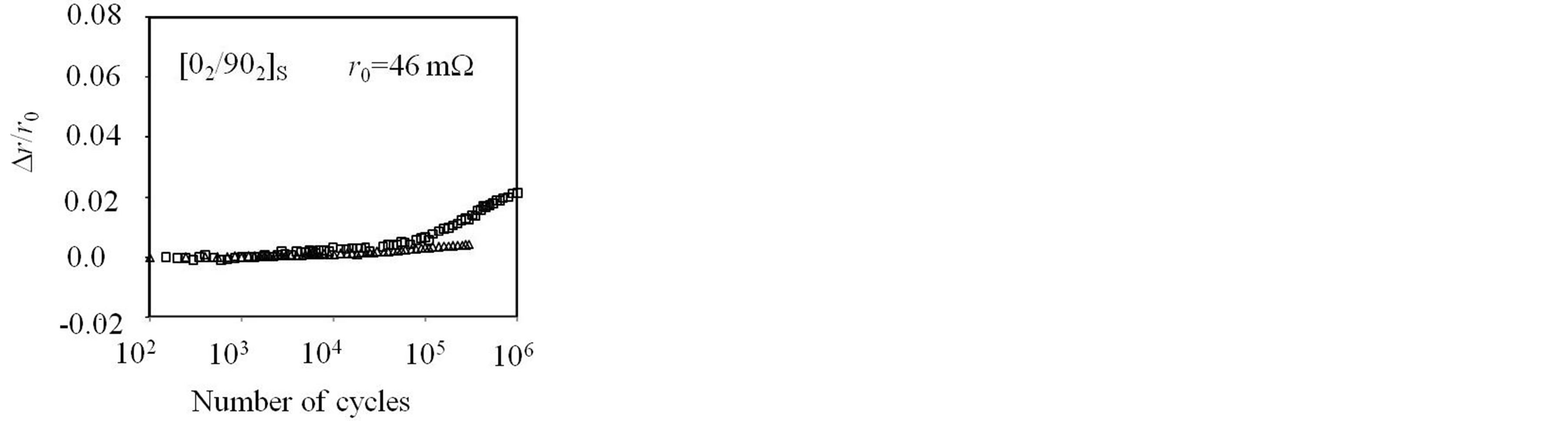 (b) Cross-ply laminate
Figure 8. Contact resistance change at electrode during cyclic loading tests.
the surface of 0˚ ply. The applied strain range in the longitudinal direction is the same for the both cases. The difference of the electrical contact resistance changes of theses laminates depends on the difference of the deformation in the transverse direction. This is discussed in the next section.
In the electrical resistance change of the cross-ply laminate in Figure 6(b), the electrical current flows in the 90˚ plies is very small compared with the electric current in the 0˚ plies. This means that the electrical contact change between the fibers in the 90˚ plies have little effect on the total electrical resistance change of the crossply specimen. This means that the increase of the electrical resistance of the cross-ply laminate in Figure 6(b)may not be the effect of the invisible small damages in the 90˚ plies. Even for the four-probe method, debonding of the electrodes to apply electric current causes slight increase of the total length of the electric current path. This causes slight increase of the electrical resistance of the specimen. As the total electric current I is constant during measuring the electric resistance, the slight increase of the electrical resistance causes the slight increase of voltage measured at the inner couple of electrodes. This causes the apparent increase of the electrical resistance. The electrical resistance increase in Figure 6(b) may include this apparent effect because no damage is observed in the specimen.
Compared with the cross-ply laminate, the results of the quasi-isotropic laminate decrease significantly as shown in Figures 5 and 6(a). The only difference between the two laminates is the existence of the ±45˚ plies. In the present study, therefore, tensile tests and cyclic loading tests of ±45˚ laminates were performed to clarify the effect of the ±45˚ laminates in the electrical resistance change.
3.3. Effect of ±45˚ Plies
As mentioned before, the difference between the electrical resistance changes of the two kinds of laminates (cross-ply laminates and the quasi-isotropic laminates) is the existence of ±45˚ plies. Although the mechanical behavior of the ±45˚ laminate is different from the quasiisotropic laminate, the electrical behavior of the ±45˚ plies is identical to the ±45˚ plies in the quasi-isotropic laminate because the electric conductance of the ±45˚ plies is the same in the both laminates (quasi-isotropic laminates and ±45˚ plies laminates). In this section, therefore, ±45˚ laminate specimen is used to investigate electrical resistance change during tensile cyclic loading of ±45˚ plies.
Figure 9 shows the stress-strain relationship of a tensile test of a ±45˚ laminate. The ordinate is the average stress and the abscissa is the measured applied strain in the longitudinal direction. As shown in Figure 9, tensile test results of ±45˚ laminate shows the non-linear relationship because of the in-plane shear plastic deformation of CFRP. Although it seems that there is a linear relationship in the small applied load up to 60 MPa, the load-unloading curve up to the 60 MPa shows the nonlinear relationship as shown in Figure 10 when it is magnified. This shows that the there is small residual strain even after the small applied load for the ±45˚ laminate under the cyclic loading. The in-plane shear plastic deformation causes the residual strain under the complete unloading condition. Using the same configuration specimen as shown in Figure 1, a tensile cyclic loading test was performed using the ±45˚ laminate, and the electrical resistance change in the longitudinal direction of the specimen was measured during the cyclic loading test. Even in this test, alternating current was used and the phase angle was zero. This means that the impedance is the same as electrical resistance for the ±45˚ laminate.
Figure 11 shows the results of measured longitudinal strain and transverse strain at the maximum loading and the completely unloading condition: the strain at the completely unloading condition means residual strain here. The symbols are the measured results, and the lines are the obtained relationship between the longitudinal stain
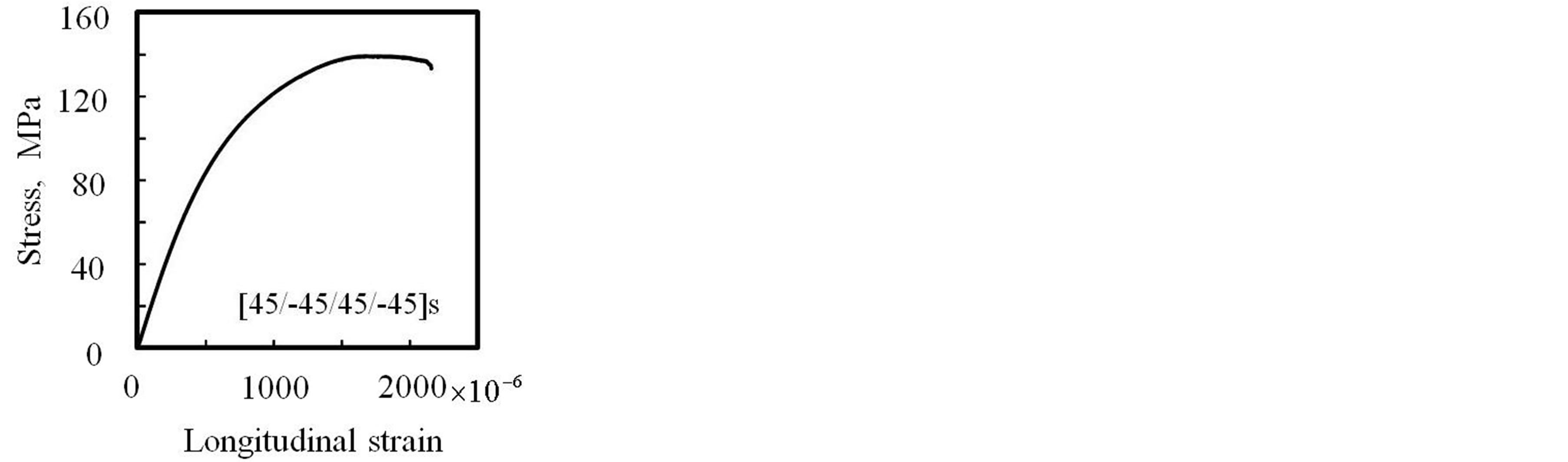
Figure 9. Stress-strain curve of ±45˚ CFRP laminate.
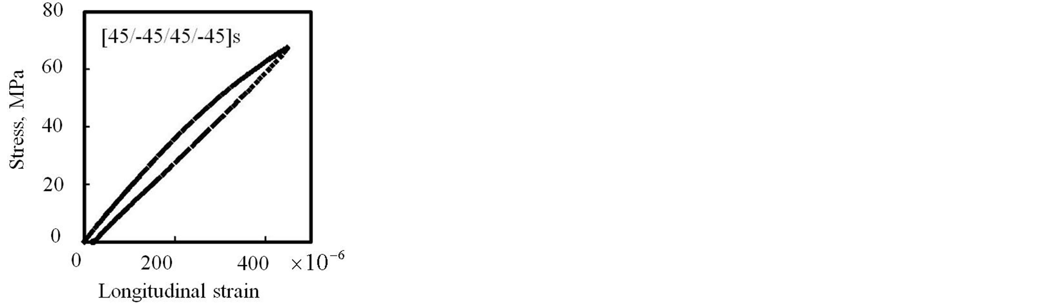
Figure 10. Magnified stress-strain curve of ±45˚ CFRP laminate.
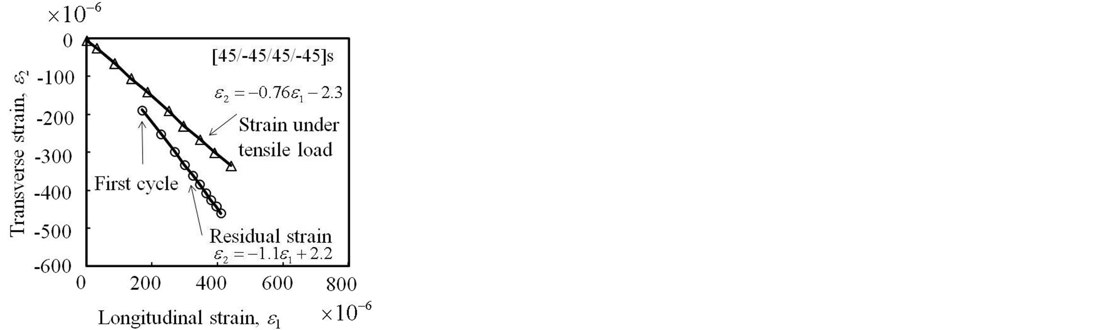
Figure 11. Measured strain at the maximum and completely unloaded condition during cyclic loading of ±45˚ CFRP laminate.
and the transverse strain using the least square-error method. The first cycle means the first result at the completely unloaded condition. The results show that the tensile test of the ±45˚ laminate has large residual strain even in the small tensile strain in the both direction. The residual transverse strain is compression strain and the magnitude of the compression strain is larger than the residual tensile strain in the longitudinal direction.
Figure 12 shows the electrical resistance change of the ±45˚ laminate after unloading. The ordinate measured residual longitudinal residual strain, and the ordinate is the residual electrical resistance change: the circle sym-
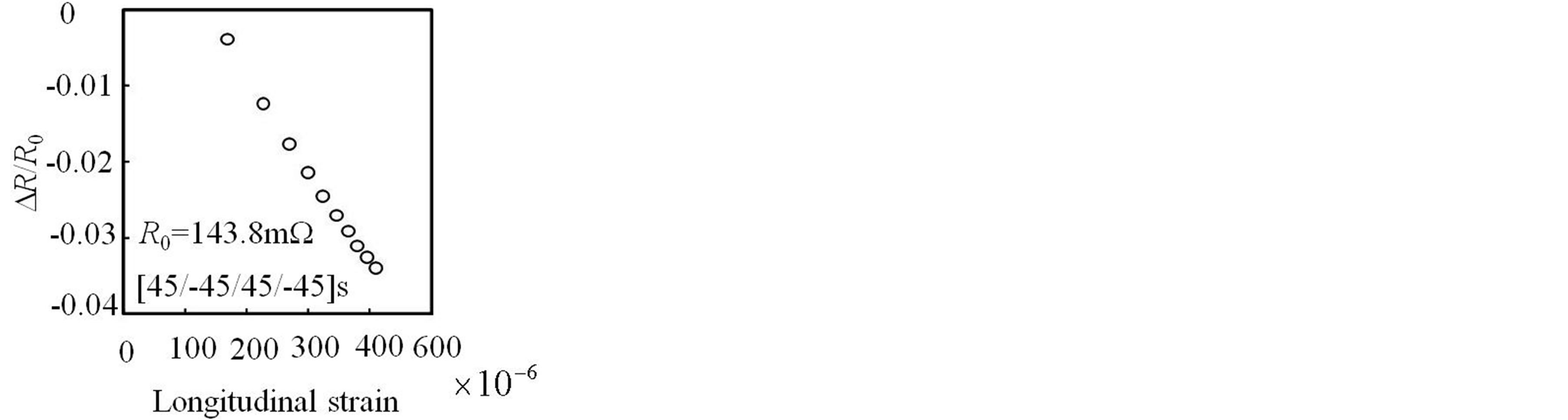
Figure 12. Measured electrical resistance change of ±45˚ CFRP laminate under the completely unloading condition.
bols are the measured results. With the increase of the residual strain at the unloading, the electrical resistance at completely unloading condition decreases significantly. Let us consider the case of the electrical resistance decrease of the ±45˚ laminate of the completely unloaded condition.
For the tensile test of the ±45˚ laminate, in-plane shear strain is applied in the plies. The electrical resistance changes during shear loading of a single ply have already reported in the reference of [23]. In the reference [23], the electrical resistance is constant under the in-plane shear loading. This indicates that two mechanisms are left as the reasons of the decrease of the electrical resistance: the first one is electrical resistance change caused by biaxial loading effect of residual plastic strain as shown in the reference [16]; the second is the effect of decrease of electric resistance in the thickness direction as shown in the reference [25] caused by the plastic in-plane shear deformation.
Let us estimate the effect of biaxial loading. Let the longitudinal strain of the specimen is ε1, and the in-plane transverse strain is ε2. As shown in Figure 12, an experimental formula between the two residual strain values is obtained.
 (2)
(2)
The strain of the fiber direction εL that inclines to the specimen longitudinal direction by 45˚ and the transverse strain εT can be obtained using the strain transformation as follows.
 (3)
(3)
Substitution of the Equation (2) into the Equation (3) gives
 (4)
(4)
Let us consider the case of ε1 = 400 μ. In the case, εL = −20 μ and εT = −20 μ. Using the electrical resistance change matrix caused by loading [16], the electrical resistance change is obtained as follows.
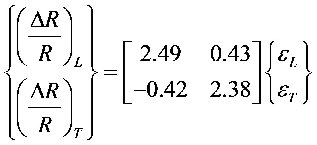 (5)
(5)
The Equation (5) tells (ΔR/R)L = −58 μ. Figure 12 shows that the electrical resistance change because of the applied biaxial strain at ε1 = 400 μ is (ΔR/R)L = −35,000 μ. This indicates that the decrease of the electrical resistance of the ±45˚ laminate cannot be explained by the electrical resistance change caused by the biaxial loading.
The electric current of the ±45˚ laminate flows in the fiber direction: the electric current in the 45˚-ply flows in the 45˚ direction. To visualize the electric current in the each ply, 3-D FEM analysis was performed here using commercially available FEM code ANSYS. For the FEM analysis, the electric conductance measured by Abry et al. [8] was used here. The FEM analysis used SOLID226 elements of 20 nodes, and the total number of elements is 3700. The input electric current is 30 mA. Figure 13 shows the results of 3-D FEM. The white arrows indicate the location of the copper electrodes. The outer couple of electrodes are used to apply the electric current and the inner couple of electrodes are used to measure the electric voltage. Figure 13 shows the vectors of electric current density, and that is the view from the top surface. As shown in Figure 13, electric current flows in the 45˚ direction in the surface 45˚-ply.
Figure 14 is the cross sectional view of Figure 2. The location of the cross section is the middle point between the electrodes shown as a white line in Figure 13. Figure 14 is the vector view of the electric current density from the electrode A. As shown by the circle, the electric current flows in the thickness direction at the specimen edge. On the top 45˚-ply, the electric current flows in the fiber direction of 45˚-ply, and the electric current flows in the thickness direction at the specimen edge. After that, the
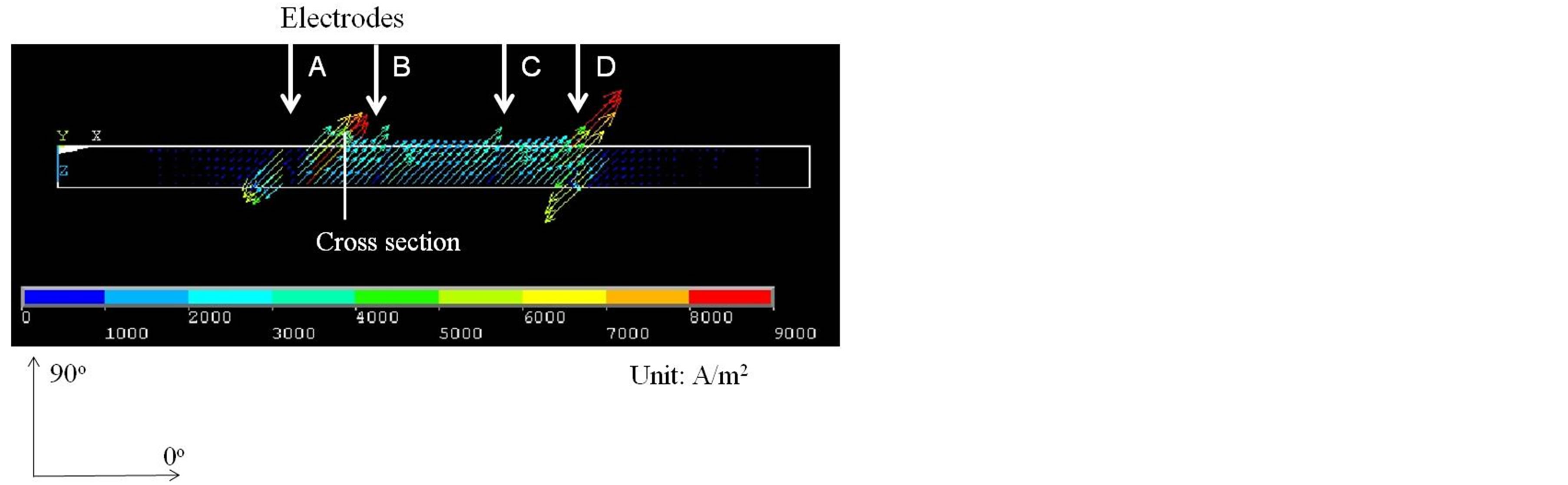
Figure 13. Electrical current density vectors of the top 45˚- ply (FEM analysis result).
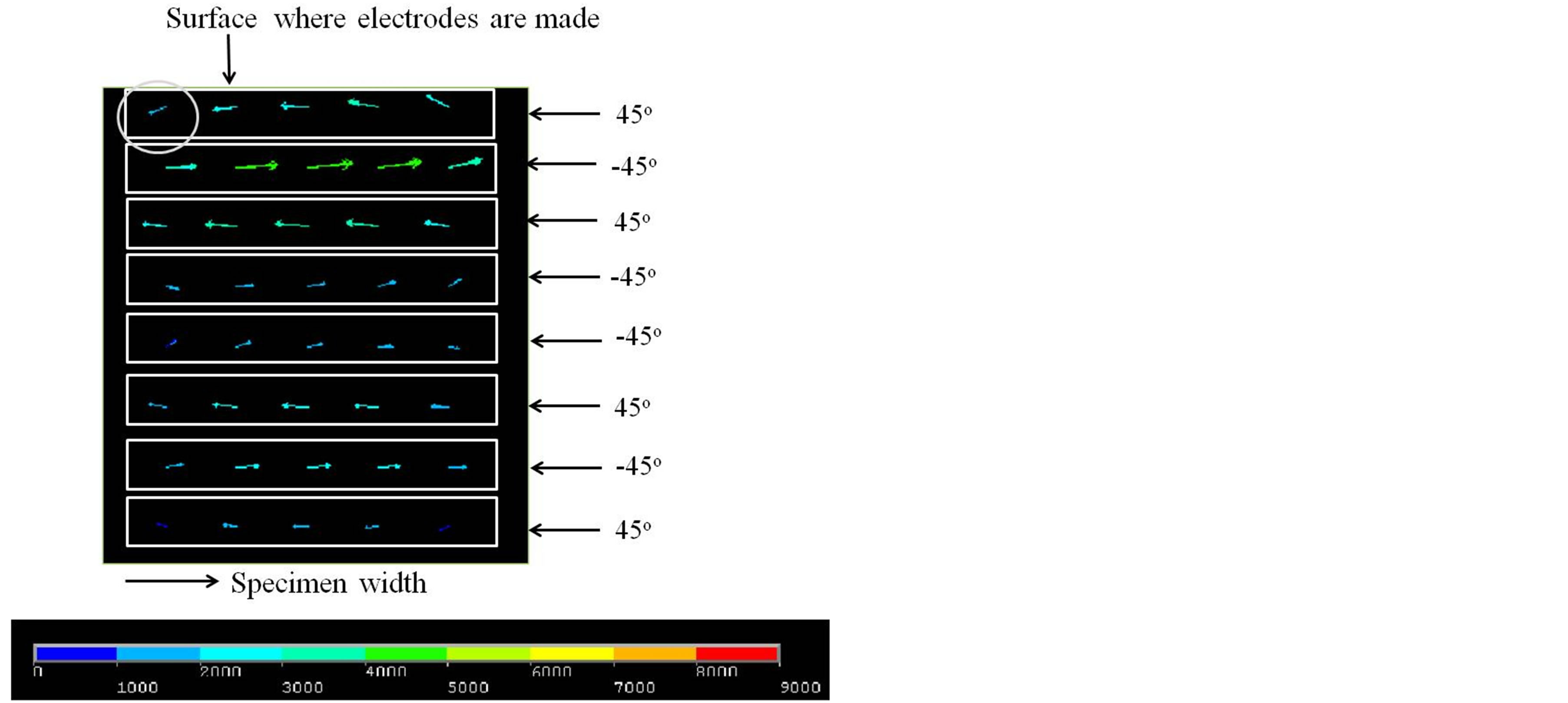
Figure 14. Electrical current density vectors of cross-section (FEM analysis result).
electric current flows in the second ply (−45˚-ply) to the −45˚ direction. This process continues until the flow reaches to the other electrode D. This process is illustrated in Figure 15. For the tensile test of the ±45˚ laminate, the plastic deformation causes elongation in the longitudinal direction, and the plastic shrink deformation is caused in the transverse direction as well as shrinkage in the thickness direction. Although it is quite difficult to confirm the plastic shrinkage in the thickness direction because of the thin CFRP laminate, the plastic shrinkage in the thickness direction causes the increase of fiber contact between the plies. This causes the decrease of the electrical resistance in the ±45˚ laminate. The elastic shrinkage of the cross-ply laminate is too small, and this can be negligible.
A small dent in the thickness direction in a CFRP plate brings significant decrease of the electrical resistance in the thickness direction in the reference [25]. Similar to the dent effect, the plastic deformation of decrease of the thickness caused the decrease of electrical resistance of the ±45˚ plies. The mechanism tells that the electric resistance in the thickness direction decreases with the tensile cyclic loading when a laminate has angle plies. This may depend on the stacking sequence and the specimen dimensions.
Generally, CFRP laminates have angles plies such as ±45˚-plies, the results of the electric current during cyclic loading of the quasi-isotropic laminate indicates that the reference electrical resistance R0 decreases with the increase of cyclic loading even when the loading does not cause damage. This shows that the simple monitoring with the electrical resistance measurement of the CFRP structures is not applicable for the actual CFRP structures.
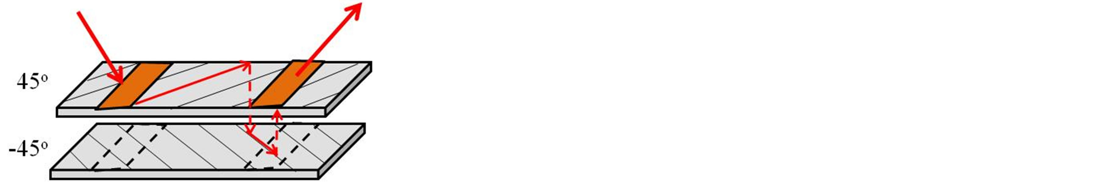
Figure 15. Schema of electric current of ±45˚ CFRP laminate.
For the long term monitoring, we have to estimate the reference resistance R0 before monitoring as shown in the reference [22].
The difference of the residual strain in the transverse direction between the cross-ply and the quasi-isotropic laminates was found here. This difference caused the difference of the damage of the electrical contact resistance in Figure 8. The large residual strain caused the large damage at the electrode of the quasi-isotropic laminate.
4. Conclusions
1) A temperature compensation method is shown, and the method is applied to the long term cyclic loading test to distinguish the effect of the cyclic loading from the temperature change.
2) Electrical contact resistance at electrodes made by copper plating increases with the increase of number of cycles for the quasi-isotropic laminates even when the applied loading is small enough to prevent damage. The residual strain in the transverse direction caused by the in-plane plastic shear deformation makes this damage at electrodes.
3) For the quasi-isotropic CFRP laminate, the plastic in-plane shear deformation of the angle plies causes the electrical resistance decrease during cyclic loading even for the small loading that does not cause damage. The plastic in-plane shear deformation caused residual elongation in the longitudinal direction. The residual elongation means the decrease of the thickness, and this caused the electrical resistance decrease for the quasi-isotropic CFRP laminate.
REFERENCES
- K. Schulte and C. Baron, “Load and Failure Analyses of CFRP Laminates by Means of Electrical Resistivity Measurements,” Composites Science and Technology, Vol. 36, No. 1, 1989, pp. 63-76. http://dx.doi.org/10.1016/0266-3538(89)90016-X
- N. Muto, H. Yanagida, T. Nakatsuji, M. Sugita and Y. Ohtsuka, “Preventing Fatal Fractures in Carbon-FibreGlass-Fibre-Reinforced Plastic Composites by Monitoring Change in Electrical Resistance,” Journal of the American Ceramic Society, Vol. 76, No. 4, 1993, pp. 875- 879.
- A. S. Kaddoour, F. A. Al-Salehi and S. T. S. Al-Hassani, “Electrical Resistance Measurement Technique for Detecting Failure in CFRP Materials at High Strain Rate,” Composites Science and Technology, Vol. 51, No. 3, 1994, pp. 377-385. http://dx.doi.org/10.1016/0266-3538(94)90107-4
- X. Wang, D. D. L. Chung, “Short Carbon Fiber Reinforced Epoxy as a Piezoresistive Strain Sensor,” Smart Materials and Structures, Vol. 4, No. 4, 1995, pp. 363- 367. http://dx.doi.org/10.1088/0964-1726/4/4/017
- A. Todoroki, K. Matsuura and H. Kobayashi, “Application of Electric Potential Method to Smart Composite Structures for Detecting Delamination,” JSME International Journal Series A, Vol. 38, No. 4, 1995, pp. 524- 530.
- P. E. Irving, C. Thiagarajan, “Fatigue Damage Characterization in Carbon Fibre Composite Materials Using an Electrical Potential Technique,” Smart Materials and Structures, Vol. 7, No. 4, 1998, pp. 456-466. http://dx.doi.org/10.1088/0964-1726/7/4/004
- D. C. Seo and J. J. Lee, “Damage Detection of CFRP Laminates Using Electrical Resistance Measurement and a Neural Network,” Composite Structures, Vol. 47, No. 1-4, 1999, pp. 525-530. http://dx.doi.org/10.1016/S0263-8223(00)00016-7
- J. C. Abry, Y. K.Choi, A. Chateauminois, B. Dalloz, G. Giraud and M. Salvia, “In-Situ Monitoring of Damage in CFRP Laminates by Using AC and DC measurements,” Composite Sciences and Technology, Vol. 61, No. 6, 2001, pp. 855-864. http://dx.doi.org/10.1016/S0266-3538(00)00181-0
- J. B. Park, T. Okabe, N. Takeda and W. A. Curtin, “Electromechanical Modeling of Unidirectional CFRP Composites under Tensile Loading Condition,” Composites Part A, Vol. 33, No. 2, 2002, pp. 267-275. http://dx.doi.org/10.1016/S1359-835X(01)00097-5
- A. Todoroki, Y. Tanaka and and Y. Shimamura, “Delamination Monitoring of Graphite/Epoxy Laminated Composite Plate of Electric Resistance Change Method,” Composites Science and Technology, Vol. 62, No. 9, 2002, pp. 1151-1160. http://dx.doi.org/10.1016/S0266-3538(02)00053-2
- A. Todoroki, Y. Tanaka and Y. Shimamura, “Delamination Monitoring of Graphite/Epoxy Laminated Composite Plate of Electric Resistance Change Method,” Composites Science and Technology, Vol. 62, No. 9, 2002, pp. 1151- 1160. http://dx.doi.org/10.1016/S0266-3538(02)00053-2
- A. Todoroki, M. Tanaka and Y. Shimamura, “Measurement of Orthotropic Electric Conductance of CFRP Laminates and Analysis of the Effect on Delamination Monitoring with Electric Resistance Change Method,” Composite Sciences and Technology, Vol. 62, No. 5, 2002, pp. 619-628.
- K. Ogi and Y. Takao, “Characterization of Piezoresistance Behavior in a CFRP Unidirectional Laminate,” Composites Science and Technology, Vol. 65, No. 2, 2005, pp. 231-239. http://dx.doi.org/10.1016/j.compscitech.2004.07.005
- N. Angelidis and P. E. Irving, “Detection of Impact Damage in cfrp laminates by Means of Electrical Potential Techniques,” Composites Science and Technology, Vol. 67, No. 3-4, 2007, pp. 594-604. http://dx.doi.org/10.1016/j.compscitech.2006.07.033
- E. Sevkat, B. Liaw and F. A. Delale, “Statistical Model of Electrical Resistance of Carbon Fiber Reinforced Composites under Tensile Loading,” Composites Science and Technology, Vol. 68, No. 10-11, 2008, pp. 2214-2219. http://dx.doi.org/10.1016/j.compscitech.2008.04.011
- I. De Baere, W. Van Paepegem and J. Degrieck, “Electrical Resistance Measurement for in Situ Monitoring of Fatigue f Carbon Fabric Composites,” International Journal of Fatigue, Vol. 32, No. 1, 2010, pp. 197-207. http://dx.doi.org/10.1016/j.ijfatigue.2009.02.044
- A. Todoroki, Y. Samejima, Y. Hirano and R. Matsuzaki, “Piezoresistivity of Unidirectional Carbon/Epoxy Composites for Multiaxial Loading,” Composites Science and Technology, Vol. 69, No. 11, 2009, pp. 1841-1846. http://dx.doi.org/10.1016/j.compscitech.2009.03.023
- A. Todoroki, Y. Samejima, Y. Hirano, R. Matsuzaki and Y. Mizutani, “Electrical Resistance Change of Thick CFRP Laminate for Self-Sensing,” Journal of Solid Mechanics and Materials Engineering (JSME), Vol. 4, No. 6, 2010, pp. 658-668. http://dx.doi.org/10.1299/jmmp.4.658
- A. Todoroki, K. Suzuki, Y. Mizutani and R. Matsuzaki, “Durability Estimates of Copper Plated Electrodes for Self-sensing CFRP Composites,” Journal of Solid Mechanics and Materials Engineering (JSME), Vol. 4, No. 6, 2010, pp. 610-620. http://dx.doi.org/10.1299/jmmp.4.610
- A. Todoroki, K. Suzuki, Y. Mizutani and R. Matsuzaki, “Electrical Resistance Change of CFRP under Compression Load,” Journal of Solid Mechanics and Materials Engineering (JSME), Vol. 4, No. 7, 2010, pp. 864-874. http://dx.doi.org/10.1299/jmmp.4.864
- Y. Suzuki, A. Todoroki, Y. Mizutani and R. Matsuzaki, “Impact Damage Detection in CFRP Using Statistical Analysis of Resistance Temperature Characteristics,” Journal of Solid Mechanics and Materials Engineering (JSME), Vol. 5, No. 1, 2011, pp. 33-43. http://dx.doi.org/10.1299/jmmp.5.33
- A. Todoroki, “Monitoring of Electric Conductance and Delamination of CFRP Using Multiple Electric Potential Measurements,” Advanced Composite Materials, in Press.
- A. Todoroki and J. Yoshida, “Electrical Resistance Change of Unidirectional CFRP Due to Applied Load,” JSME International Journal—Series A, Vol. 47, No. 3, 2004, pp. 357-364. http://dx.doi.org/10.1299/jsmea.47.357
- A. Todoroki, K. Omagari, Y. Shimamura and H. Kobayashi, “Matrix Crack Detection of CFRP Using Electrical Resistance Change with Integrated Surface Probes,” Composites Science and Technology, Vol. 66, No. 11-12, 2006, pp. 1539-1545. http://dx.doi.org/10.1016/j.compscitech.2005.11.029
- A. Todoroki, Y. Shimazu and Y. Mizitani, “Electrical Resistance Reduction of Laminated Carbon Fiber Reinforced Polymer by Dent made by indentation without cracking,” Journal of Solid Mechanics and Materials Engineering (JSME), Vol. 6, No. 12, 2012, pp. 1042-1052. http://dx.doi.org/10.1299/jmmp.6.1042
NOTES
*Corresponding author.