Journal of Power and Energy Engineering
Vol.05 No.07(2017), Article ID:77879,11 pages
10.4236/jpee.2017.57003
Counter-Rotating Type Horizontal-Axis Bidirectional Propellers for Tidal Stream Power Unit
Yuki Funami1*, Yuji Nakanishi1, Nak-Joong Lee2, Bin Huang3, Toshiaki Kanemoto4
1Faculty of Engineering, Kanagawa University, Yokohama, Japan
2Faculty of Engineering, Kyushu Institute of Technology, Kitakyushu, Japan
3Ocean College, Zhejiang University, Zhoushan, China
4Institute of Ocean Energy, Saga University, Saga, Japan

Copyright © 2017 by authors and Scientific Research Publishing Inc.
This work is licensed under the Creative Commons Attribution International License (CC BY 4.0).
http://creativecommons.org/licenses/by/4.0/


Received: June 15, 2017; Accepted: July 22, 2017; Published: July 25, 2017
ABSTRACT
Tidal stream power units with horizontal-axis propellers are one of promising technologies for generating the renewable green energy. The ebb and flow require that the power unit must operate in bidirectional tidal streams. Hence a tidal stream power unit with counter-rotating type horizontal-axis bidirectional propellers is proposed in this paper. The blades with fully-symmetrical hydrofoils were optimized numerically. The output and flow conditions predicted by the computational fluid dynamics simulations are compared with the results of the wind tunnel experiments at the higher tip speed ratios, which are of expected usual operating conditions of this unit. The numerical and experimental results show good agreements. It is also confirmed that the flow discharged from the counter-rotating type propellers has no swirling component, though the single propeller generates the unacceptable swirling component.
Keywords:
Bidirectional Propellers, Counter-Rotating Type Machine, Tidal Stream Power Unit, Computational Fluid Dynamics

1. Introduction
Currently, extreme increase of the demand for energy leads to the depletion of fossil fuel and higher energy prices. As a result, renewable green energy independent of fossil fuel is required in order to get sustainable society. Tidal stream power generation is one of promising technologies for generating the renewable green energy. This has some advantages as high energy intensity, predictability of tides and so on [1] . The effort to achieve the practical use of the power generation has been made in the world, including Japan. In order to apply to tidal stream power generation, various kinds of power units with a tidal turbine have been proposed. Especially, horizontal-axis tidal turbines have been developed [1] . Design methodologies and technologies in the wind turbine industry can be applied to horizontal-axis tidal turbines because of their similar working principles; the kinetic energy of fluid is converted to the electric energy when the flow drives a propeller and generator of the turbine [2] .
Tidal streams change their directions owing to the ebb and flow. Hence tidal turbines must operate in bidirectional tidal streams. Some types of bidirectional tidal turbine were suggested, as mentioned by Liu et al. [3] [4] . One of the bidirectional tidal turbines can alternate its orientations. Another one has a control system of blade pitch angle. Other one has a bidirectional propeller with a fully symmetrical hydrofoil, which is called bidirectional hydrofoil. The last type of the turbines does not require a high-cost device such as pitch control system. Another merit of it, reported by Nedyalkov et al. [5] , is that the bidirectional hydrofoil cavitates at lower cavitation number compared to the unidirectional hydrofoil.
Kanemoto et al. proposed a unique counter-rotating type horizontal-axis water turbine [6] . It was applied to tidal stream power unit [7] . The schematic of the tidal stream power unit with the counter-rotating type horizontal-axis propellers is shown in Figure 1. The power unit has the horizontal-axis tandem propellers and the peculiar synchronous generator with double rotational armatures. In the nacelle, the front propeller and the rear propeller counter drive the outer and the inner armature of the generator, respectively. Relative rotational speed between the armatures is two times as high as that of a conventional generator. This provides some advantages. One of the advantages is that the output voltage is two times higher when the rotational speed and the generator size are the same. In other words, the diameter of the propeller can be reduced when the output voltage and the rotational speed are the same. Another one is that cavitation can be suppressed because the individual rotational speed can be reduced at
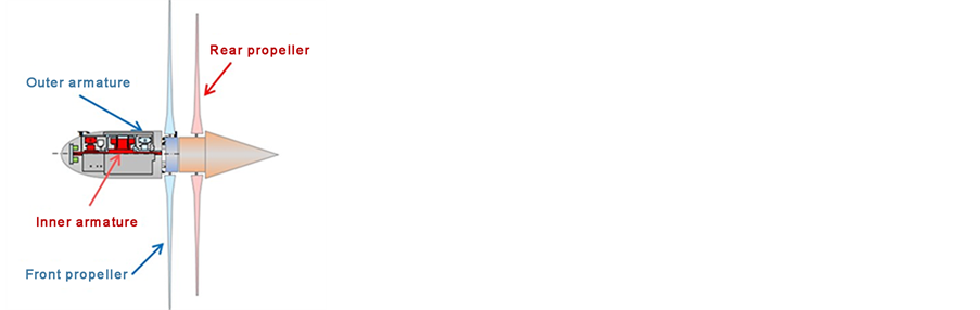
Figure 1. Tidal stream power unit with the counter-rotating type horizontal-axis propellers.
the same voltage and size. Besides, rotational torques are counter-balanced and no reaction force arises. That is, it is not necessary to prepare the solid mounting bed and pile.
In this paper, we propose counter-rotating type horizontal-axis bidirectional propellers installed in a tidal stream power unit. The blades with fully-symme- trical hydrofoils, optimized numerically by Huang et al. [8] , are employed. Computational fluid dynamics (CFD) simulations of the bidirectional propellers are carried out and these results are compared with the results of the wind tunnel experiments [9] . The flow characteristics of the bidirectional propellers are discussed.
2. Preparation of Bidirectional Propellers
In this paper, we employ the bidirectional propellers which Huang et al. designed by the traditional blade element momentum (BEM) theory [8] . The detail of the bidirectional propellers designed by Huang et al. is described below.
The original hydrofoil was based on the NACA 16-015 airfoil. While the first half of the original hydrofoil was the same as NACA 16-015, the second half of it was the mirror portion of the first half. This original hydrofoil, hence, was fully symmetrical on the suction side, pressure side, leading edge and trailing edge.
The hydrofoil was adopted to the design of the blade. The blade pitch angle and chord distributions were determined with the traditional BEM theory. It is noted that the blade was designed for getting the best efficiency at the tip speed ratio (TSR) of 3.5.
In order to increase the lift-drag ratio of the original hydrofoil, the optimized hydrofoils were developed with the multi-objective optimization algorithm.
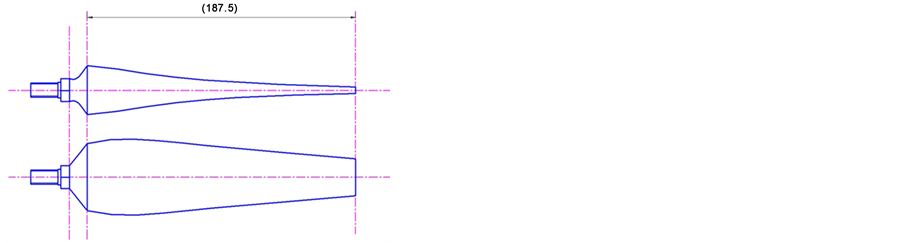
The blade profiles of the propellers designed are shown in Figure 2. Because of the operations in bidirectional tidal streams, the front and rear propellers had the same geometry, size and number of blades. The diameter of both propellers was 500 mm. The number of blades of both propellers was 3.
3. Experimental Setup
In order to obtain the performance characteristics of the counter-rotating type horizontal-axis propellers operating in bidirectional tidal streams, the performance and flow conditions have been investigated in the wind tunnel [9] . The experimental results are compared to numerical results later.
In these experiments, the setting angle of the blades can be adjusted easily. The wind tunnel experiments have been performed in various combinations of blade setting angles,  and
and , of the front and rear propellers in [9] . However, only the case of
  [degree] and
  [degree] is considered in this paper.
The wind velocity  was set to about 10 m/s. The total tip speed ratio
  was in the range of 2 to 11, which was defined below;
 , (1)
, (1)
 (a) Overview
 (b) Example of the blade profiles
Figure 2. The blade of the bidirectional propellers.
 , (2)
, (2)
 , (3)
, (3)
where  is tip speed ratio,
  is rotational speed,
  is radius, subscript
  is total,
  is front propeller and
  is rear propeller. When Reynolds number was defined based on propeller diameter and peripheral speed of the front propeller, it was in the range of 3.3 × 10⁵ to 1.7 × 10⁶.
4. Numerical Setup
CFD simulations are performed in order to obtain performance characteristics and flow characteristics of the counter-rotating type horizontal-axis bidirectional propellers installed in a tidal stream power unit.
4.1. Mesh Generation
The front and rear propellers are attached to a capsule-shape nacelle, which is 355 mm long and 90 mm diameter. The computational domain is a rectangular domain surrounding the propellers. The size of the domain is 1000 mm × 1500 mm × 5000 mm, in other words,  , where D means propeller diameter. This domain is divided into three blocks, as shown in Figure 3. One block, labeled as “Front Region”, is the region including the front propeller. Another one, labeled as “Rear Region”, includes the rear propeller. The other one is the rest region and is labeled as “Surrounding Region”. For the sake of the reduction of computational costs, the block Front Region and Rear Region are built in a 120 degree segment and include only one blade of the propellers. The rotational periodic conditions are imposed on the interfaces between adjacent segments.
Computational meshes are generated by ANSYS ICEM CFD 16.2. Unstructured tetra type meshes are employed. Delaunay method is selected in mesh
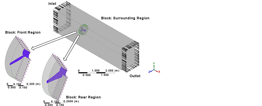
Figure 3. Three blocks of the numerical domain.
generation. Prism layers are created only around the blades of both propellers. The number of layers is set to 15.
The initial height of the layer is 0.005 mm and the growth ratio of height is 1.2. The maximum dimensionless wall distance  on the blades is less than 5. The mesh statistics are shown at Table 1.
4.2. Numerical Settings
CFD simulations are performed by using ANSYS CFX 16.2, which is a commercial CFD solver. Incompressible Navier-Stokes equations and equation of continuity are solved with the shear stress transport (SST)  turbulence model [10] . The numerical settings are summarized at Table 2. The boundary “Inlet” in Figure 3 is set to inlet boundary where the normal speed and turbulent intensity is specified, while the boundary “Outlet” is set to outlet boundary where the average static pressure is specified, as shown at Table 2. The other boundaries are set to no slip, smooth wall. The stage model is applied to the interface connections between the blocks of the numerical domain. In this model, the fluxes through bands on the interface are circumferentially averaged [11] .
The CFD simulations are performed at the total TSRs over 6, which are of expected usual operating conditions of this unit. The TSR combinations of the front and rear propellers are set so that front and rear torques may be equal. In these total TSRs, the Reynolds number defined before is in the range of 1.1 × 10⁶ to 1.6 × 10⁶.
Besides the residuals of mass, momentum and energy, some important parameters such as power coefficient and torque are monitored at each iteration step. In all simulations, the convergence of the solution is checked from the histories of these monitored values.
5. Results and Discussion
The experimental and numerical results are compared in terms of the performance characteristics of the bidirectional propellers. Flow characteristics of the bidirectional propellers are discussed in the numerical results.

Table 1. Mesh statistics.
Table 2. Numerical settings.
5.1. Performance Characteristics
Total power coefficients and total torque coefficients are calculated by the following equations;
 , (4)
, (4)
 , (5)
, (5)
 , (6)
, (6)
 , (7)
, (7)
 , (8)
, (8)
 , (9)
, (9)
where  is power coefficient,
  is torque,
  is fluid density,
  is swept area and
  is torque coefficient. The total power and torque coefficients are shown in Figure 4 and Figure 5, respectively.
As one can see in Figure 4, the total power coefficients of the simulations coincide with those of the experiments. The total power coefficients have the peak around the total TSR . This peak is called the best efficiency point (BEP). The maximum value at the BEP is about 0.33.
In Figure 5, the variations of total torque coefficient are relatively small in the total TSRs less than 7. After passing over the point at the total TSR of 7, which is
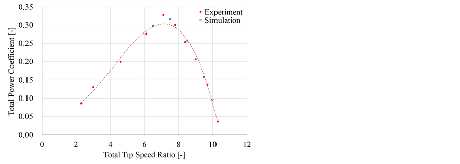
Figure 4. Total power coefficients in the experiments and simulations. The broken line is obtained by fitting the experimental results to a cubic curve using the least-square method.
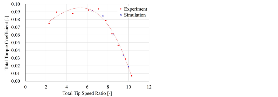
Figure 5. Total torque coefficients in the experiments and simulations. The broken line is obtained by fitting the experimental results to a cubic curve using the least-square method.
the best efficiency point, the value of total torque coefficient decreases rapidly with increasing total TSR. The total torque coefficients of the simulations are consistent with those of the experiments in the range of the total TSR over 7.
In both the total power and torque coefficients, the numerical results coincide not only with the fitting curve of the experimental results but also with the tendency of the experimental values around their peaks.
5.2. Flow Characteristics
The pressure fields and stream lines, obtained by the simulations, at the radial position  in the case of the total TSR of 7.50 (a little higher than the total TSR of the BEP), 6.50 (a little less than the total TSR of the BEP) and 10.0 (much higher than the total TSR of the BEP) are shown in Figure 6, Figure 7 and Figure 8, respectively. At the total TSR of 7.50 (a little higher than the total TSR of the BEP), attached flows along the blade surfaces of the front and rear propeller are observed. At the total TSR of 6.50 which is a little less than the total TSR of the BEP, the flow around the blade of the front propeller follows the

Figure 6. Pressure field and stream lines at  in the case of
  (a little higher than the total TSR of the BEP). The left of the figure is the front of the unit, while the right is the rear.
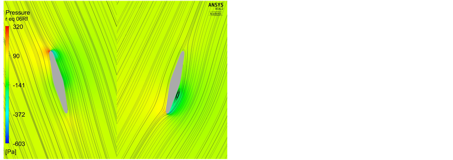
Figure 7. Pressure field and stream lines at  in the case of
  (a little less than the total TSR of the BEP). The left of the figure is the front of the unit, while the right is the rear.
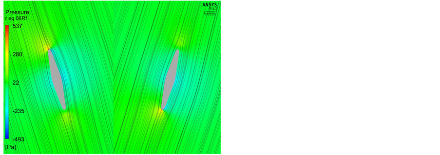
Figure 8. Pressure field and stream lines at  in the case of
  (much higher than the total TSR of the BEP). The left of the figure is the front of the unit, while the right is the rear.
blade surface, while a flow separation and reattachment arises around the blade of the rear propeller. At the total TSR of 10.0, although the total TSR is much higher than that of the BEP, the flows around the blades of both propellers follow the blade surfaces.
The stream lines in the case of the total TSR of 7.50, 6.50 and 10.0 are shown in Figure 9, Figure 10 and Figure 11, respectively. Compared to the single propeller case as shown in Figure 12, the swirl component of velocity is diminished with the counter-rotating type propellers. The reason is that the angular momentum change through the front propeller equals to that through the rear propeller. This is an advantage in array design of tidal stream power units, because interactions among the power units through swirling wakes are reduced.
6. Conclusions
We proposed the counter-rotating type horizontal-axis bidirectional propellers installed in a tidal stream power unit. The blades with fully-symmetrical
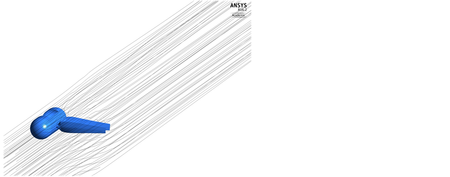
Figure 9. Stream lines in the case of  (a little higher than the total TSR of the BEP).

Figure 10. Stream lines in the case of  (a little less than the total TSR of the BEP).

Figure 11. Stream lines in the case of  (much higher than the total TSR of the BEP).

Figure 12. Stream lines in the case of the single propeller at the TSR of 3.5 which is the best efficiency point.
hydrofoils were optimized numerically. CFD simulations of the bidirectional propellers were carried out and these results were compared with the results of the wind tunnel experiments. The numerical and experimental results show good agreements. The conclusions are obtained as follow;
・ The total power coefficient has the maximum value, which is about 0.33, around the total TSR of approximately 7.
・ The total torque coefficient drops rapidly after passing over the point at the total TSR of 7.
・ The flow discharged from the counter-rotating type propellers has no swirl component, though the single propeller generates the unacceptable swirling component.
The performance and flow characteristics of the bidirectional propellers were evaluated well by the CFD simulations and wind tunnel experiments.
Acknowledgements
This research was performed as part of “Development Project of Counter-Ro- tating Type Tidal Stream Power Unit” supported by the New Energy and Industrial Technology Development Organization (NEDO) in Japan. The authors wish to thank concerned parties in NEDO, EIM Electric Co., Ltd., Kyowa Engineering Consultants Co., Ltd., Maeda Corporation, Eagle Industry Co., Ltd., Waseda University, Kyushu Institute of Technology and Saga University.
Cite this paper
Funami, Y., Nakanishi, Y., Lee, N.-J., Huang, B. and Kanemoto, T. (2017) Counter-Rotating Type Horizontal-Axis Bidirectional Propellers for Tidal Stream Power Unit. Journal of Power and Energy Engineering, 5, 34-44. https://doi.org/10.4236/jpee.2017.57003
References
- 1. Fraenkel, P.L. (2002) Power from Marine Currents. Proceedings of the Institution of Me-chanical Engineers, Part A: Journal of Power and Energy, 216, 1-14.
https://doi.org/10.1243/095765002760024782 - 2. Benelghali, S.E., Benhouzid, M.E.H. and Charpentir, J.F. (2007) Marine Tidal Current Electric Power Generation Technology: State of the Art and Current Status. Proceedings of the IEEE International Electric Machines & Drives Conference, Antalya, 3-5 May 2007, 1407-1412.
- 3. Liu, P. and Bose, N. (2012) Prototyping a Series of Bi-Directional Horizontal Axis Tidal Turbines for Optimum Energy Conversion. Applied Energy, 99, 50-66.
https://doi.org/10.1016/j.apenergy.2012.04.042 - 4. Liu, P., Bose, N., Frost, R., Macfarlane, G., Lilienthal, T., Penesis, I., Windsor, F. and Thomas, G. (2014) Model Testing of a Series of Bi-Directional Tidal Turbine Rotors. Energy, 67, 397-410.
https://doi.org/10.1016/j.energy.2013.12.058 - 5. Nedyalkov, I., and Wosnik, M. (2013) Cavitation Investigation of Hydrofoils for Marine Hydrokinetic Turbines. Proceedings of the ASME 2013 Fluids Engineering Division Summer Meeting, Incline Village, 7-11 July 2013, FEDSM2013-16576.
https://doi.org/10.1115/fedsm2013-16576 - 6. Kanemoto, T., Kaneko, M., Tanaka, D. and Yagi, T. (2000) Development of Coun-ter-Rotating Type Machine for Water Power Generation (1st Report, Counter-Rotating Type Generator and Axial-Flow Runners). Transaction of the Japan Society of Mechanical Engineers, Series B, 66, 644, 194-200 (in Japanese).
- 7. Kanemoto, T., Tanaka, D., Kashiwabara, T., Uno, M. and Nemoto, M. (2000) Coun-ter-Rotating Type Machine Suitable for Tidal Current Power Generation. Proceedings of the Tenth International Offshore and Polar Engineering Conference, Seattle, 28 May-2 June 2000, 472-477.
- 8. Huang, B., Zhu, G.J. and Kanemoto, T. (2016) Design and Performance Enhancement of a Bi-Directional Counter-Rotating Type Horizontal Axis Tidal Turbine. Ocean En-gineering, 128, 116-123.
https://doi.org/10.1016/j.oceaneng.2016.10.012 - 9. Kanemoto, T., Lee, N.-J., Heo, M.-W., Huang, B., Nakanishi, Y. and Funami, Y. (2016) Counter-Rotating Turbine in Unique Power Unit Provided for Bidirectional Tidal Streams. Proceedings of the Twelfth ISOPE Pacific-Asia Offshore Mechanics Symposium, Gold Coast, 4-7 October 2016, ISOPE-P-16-097.
- 10. ANSYS, Inc. (2015) ANSYS CFX-Solver Theory Guide, Release 16.2.
- 11. ANSYS, Inc. (2015) ANSYS CFX-Solver Modeling Guide, Release 16.2.