Journal of Power and Energy Engineering
Vol.05 No.01(2017), Article ID:73470,11 pages
10.4236/jpee.2017.51003
Comparison between SiC- and Si-Based Inverters for Photovoltaic Power Generation Systems
Yuji Ando1, Yasuhiro Shirahata1, Takeo Oku1*, Taisuke Matsumoto1, Yuya Ohishi1, Masashi Yasuda2, Akio Shimono3, Yoshikazu Takeda3, Mikio Murozono4
1Department of Materials Science, The University of Shiga Prefecture, Shiga, Japan
2Collaborative Research Center, The University of Shiga Prefecture, Shiga, Japan
3Kyoshin Electric Company Limited, Kyoto, Japan
4Clean Venture 21 Corporation, Kyoto, Japan

Copyright © 2017 by authors and Scientific Research Publishing Inc.
This work is licensed under the Creative Commons Attribution International License (CC BY 4.0).
http://creativecommons.org/licenses/by/4.0/


Received: November 1, 2016; Accepted: January 10, 2017; Published: January 13, 2017
ABSTRACT
100-W class power storage systems were developed, which comprised spherical Si solar cells, a maximum power point tracking charge controller, a lithium-ion battery, and one of two different types of direct current (DC)-alter- nating current (AC) converters. One inverter used SiC metal-oxide-semicon- ductor field-effect transistors (MOSFETs) as switching devices while the other used Si MOSFETs. In these 100-W class inverters, the ON resistance was considered to have little influence on the efficiency. Nevertheless, the SiC-based inverter exhibited an approximately 3% higher DC-AC conversion efficiency than the Si-based inverter. Power loss analysis indicated that the higher efficiency resulted predominantly from lower switching and reverse recovery losses in the SiC MOSFETs compared with in the Si MOSFETs.
Keywords:
Silicon Carbide, Solar Cell, Inverter, Photovoltaic Device, Maximum Power Point Tracking, Lithium-Ion Battery

1. Introduction
Modern power device requirements include a high blocking voltage, a low ON resistance, a high switching frequency, and good reliability. These requirements have led to great interest in power devices based on wide gap semiconductors such as GaN and SiC [1] [2] [3] . The main advantage of wide gap semiconductors is their very high electric field capability. Wide gap semiconductors possess high critical field strengths. This means that a thinner epi layer is required to block the same voltage compared with Si devices. Thus, switching devices with much lower ON resistances can be fabricated using GaN or SiC. A lower ON resistance improves the efficiency of inverters due to reduced conduction and switching losses, and also decreases the module size due to the increased power density. The high electron mobility of GaN allows switching operations with higher frequencies, which also decreases the module size because of the smaller passive components. The excellent thermal stability of SiC and GaN should enable devices based on these materials to operate at high temperatures. The improvement in system performance that can be achieved by an improvement in device performance is an important consideration for such devices. Considerable research has focused on developing power converters using SiC devices in an attempt to answer this question [4] - [11] . A comparative study for Si- and SiC- based power converters was also reported in [12] [13] . In these papers, the power converters were examined as a stand-alone equipment. Concerning photovoltaic power applications, however, performances of total systems using these converters should be also compared.
In this study, Si- and SiC-based inverters were compared with respect to performance of the total system including solar cell panels, a maximum power point tracking (MPPT) controller, and a storage battery as well as the inverter. We developed photovoltaic power generation systems based on two different direct current (DC)-alternating current (AC) converters. One inverter contained SiC metal-oxide-semiconductor field-effect transistors (MOSFETs) as switching devices while the other inverter contained Si MOSFETs. Stabilities of electrical power and DC-AC conversion efficiencies of the SiC- and Si-based systems were measured and compared. The compositions of power losses were also analyzed to understand the physical origin of the conversion losses in these systems. The capacity of handling power was set at around 100 W to enable portability. Lightweight spherical Si cell panels [14] were used as the power source. Spherical Si cells that are lightweight, flexible, and economical are suitable for self-sus- taining energy systems such as portable electronic devices, solar-powered cars, and emergency power supply systems. This study also aimed to evaluate the feasibility of the photo-voltaic power generation system based on spherical Si cells and the SiC-based inverter.
2. Materials and Methods
Figure 1 shows a schematic of the photovoltaic power generation systems. We previously reported two systems capable of operating independently, based on two different DC-AC converters [15] [16] [17] . One inverter contained Si MOSFETs as switching devices (Daiji Industry, SXCD-300) while the other contained SiC MOSFETs. The SiC-based inverter was prepared by replacing Si MOSFETs (Fairchild, FQPF16N25C) [18] in SXCD-300 with SiC MOSFETs (Rohm, SCT2120AF) [19] . The inverter consisted of a front stage DC-DC converter followed by a second stage DC-AC converter. The Si MOSFETs of the
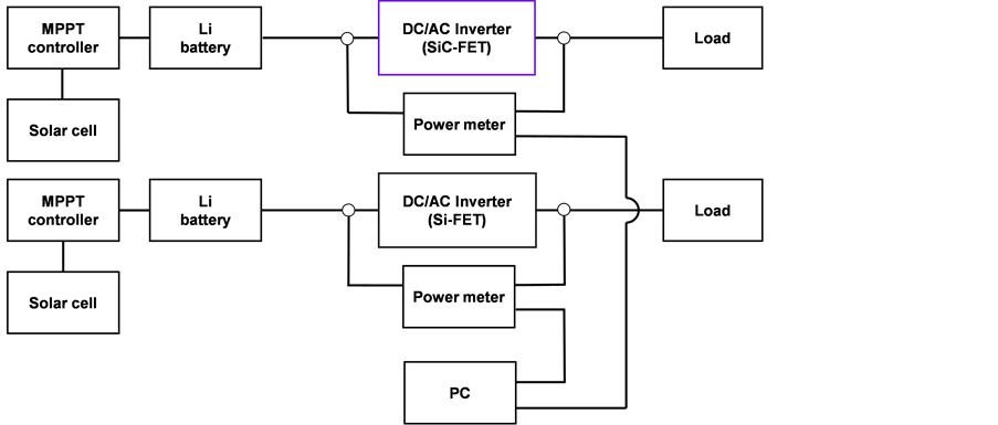
Figure 1. Schematic of the photovoltaic power generation systems consisting of spherical Si solar cells and Si- or SiC-based DC-AC converters.
DC-DC part exhibited a very low ON resistance of 4 mΩ, so SiC MOSFETs were introduced only in the DC-AC part. The input and output powers of these inverters were monitored synchronously by two power meters (Hioki, PW3336). The measurement interval was 200 ms and reported data are the average measurements over each minute. The spherical Si solar cell panels (Clean venture 21, CVFM-0540T2-WH) wired in parallel were used as the power source. The maximum operating current and voltage for a single solar panel were 3.34 A and 16.2 V, respectively. The operating point was controlled to maximize the output power, with the aid of an MPPT controller (EPsolar, Tracer-2215BN). The MPPT stabilized the electricity by charging and discharging Li-ion batteries (O’Cell, IFM12-200E2). Filament lamps were used as the load. The temperature, humidity (Hioki, LR5001) and solar radiation power (Uizin, UIZ-PCM01-LR) were monitored simultaneously during measurements.
3. Results
3.1. Stability of Electricity
Figures 2(a)-(d) show examples of the variation in voltage, current, power, and DC-AC conversion efficiency, respectively, for the SiC- and Si-based inverters. The load power was set at 90 W. Figure 3(a) and Figure 3(b) show the variation in solar radiation power and in temperature and humidity, respectively, during the measurements shown in Figure 2. In accordance with lowering of the solar radiation power after 14:30, a voltage reduction of the Li-ion battery became significant in the Si inverter system, which resulted in a gradual decrease in the input voltage (Vin). However, the input power (Pin) was almost kept constant due to the constant load power, and hence, the input current (Iin) was gradually increased. This kind of behavior was less significant in the SiC inverter system where the conversion efficiency was higher than that of the Si inverter system. Concerning the output voltage (Vout), current (Iout), and power (Pout), no fluctuation was observed in both systems. The DC-AC conversion efficiency increased

Figure 2. Variation in (a) voltage, (b) current, (c) and power at input and output terminals, and (d) DC-AC conversion efficiencies, of Si and SiC-based inverters at a load power of 90 W.

Figure 3. Variation in (a) solar radiation power and (b) temperature and humidity, during the measurements shown in Figure 2.
from 83.4 to 86.5% using the SiC-based inverter. Thus, losses were reduced from 16.6 to 13.5% using the SiC-based inverter. This efficiency improvement in the SiC inverter was considered as a result of reduced switching and reverse recovery losses in the SiC MOSFETs, which are discussed in the next section.
Figure 4(a) and Figure 4(b) show another example of the variation in power and DC-AC conversion efficiency, respectively, for Si- and SiC-based inverters. The load power was set at 10 W. In this case, discharge of the Li-ion battery was hardly observed. The currents (Iin and Iout) and voltages (Vin and Vout) were almost constant throughout a whole measurement, but an initial decrease was observed in the input power (Figure 4(a)), which would be due to an initial variation of the efficiency. Besides, there was no significant difference in the efficiencies of the SiC- and Si-based inverters, as shown in Figure 4(b). Under low output power conditions (Pout < 20 W), the efficiency was predominantly determined by the non-load losses due to the transformers in the DC-DC converter circuit, the electrolytic capacitors of the filter circuit, and so on. Since the present
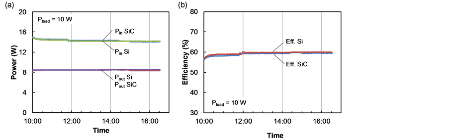
Figure 4. Variation in (a) input and output powers and (b) DC-AC conversion efficiencies of Si- and SiC-based inverters, at a load power of 10 W.
SiC inverter was provided by just replacing a Si switch in the Si inverter with a SiC switch, non-load losses were considered to be invariable between them, and hence, no significant difference was expected in the efficiencies under low output power conditions.
3.2. Conversion Efficiencies
Two different measurements were carried out to study the influence of output power on the DC-AC conversion efficiency. One was the step load measurement, where the load power was increased stepwise from 5 to 179 W, and held at each step for 5 min. The other was the steady state measurement, where the load power was kept constant, and the DC-AC conversion efficiency was determined by time average for 1 or 2-hour duration measurements after the initial variation. Figure 5(a) and Figure 5(b) show the results for the step load and steady state measurements, respectively. In these figures, DC-AC conversion efficiencies are plotted with respect to the output power. In Figure 5(b), the output power dependence was obtained by setting the constant load value to be 5, 10, 20, 54, 90, 120, 154, and 179 W. For the step load measurement, the efficiencies at an output power of 54 - 179 W were approximately 86 and 81% for the SiC- and Si-based inverters, respectively. The difference in the efficiencies of the SiC- and Si-based inverters was approximately 5%, which decreased to approximately 3% under steady state measurement. This may have been attributed to the fact that the initial variation was more significant for the Si-based inverter than the SiC- based inverter. The decrease in efficiency at the low output power region also suggested the presence of non-load losses that were independent of the load power.
4. Loss Analysis
The conduction loss of an inverter consists of contributions from a field-effect transistor (FET) (Pfet) and a body diode (BD) implemented between the source and drain (Pbd). Assuming a sinusoidal load current, Pfet and Pbd are expressed by [20] :
 (1)
(1)
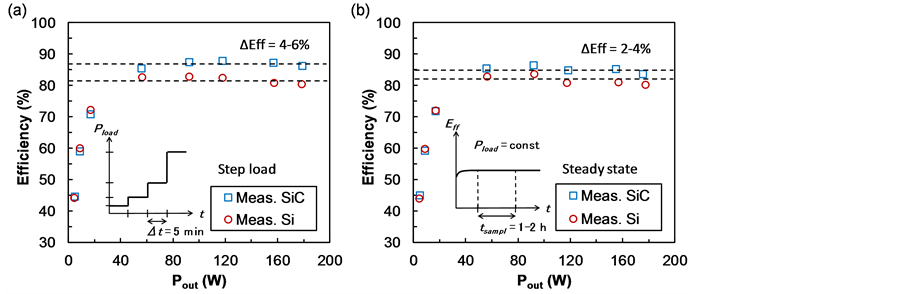
Figure 5. DC-AC conversion efficiencies versus output power for Si- and SiC-based inverters measured under (a) step load and (b) steady state conditions.
and
 (2)
(2)
where Rds, Vf, I, D, and θ are the ON resistance of the FET, forward voltage of the BD, peak load current, modulation index, and power factor angle, respectively. The switching loss of the FET consists of contributions from the turn-on loss (Pon) and turn-off loss (Poff), which are expressed by [20] :
 (3)
(3)
and
 (4)
(4)
where Kg, V, and fsw are the correction factor, peak load voltage, and switching frequency, respectively. Eon and Eoff are the turn-on and turn-off losses, respectively, for the test voltage Vt and current It. The reverse recovery loss of the BD is expressed by:
 (5)
(5)
where Irr and trr are the reverse recovery current and reverse recovery time, respectively. The total loss Ptot of the DC-AC converter is then given by:
 (6)
(6)
where Pnl is the non-load loss.
Table 1 summarizes the electrical characteristics for the SiC and Si MOSFETs operated at T = 25˚C. These parameters were taken from data sheets for SCT2120AF [19] and FQPF16N25C [18] . Although no data were available for Eon and Eoff in [18] , the switching times were approximately three times larger in FQPF16N25C than in SCT2120AF. For Eon and Eoff in FQPF16N25C, the

Table 1. Electrical characteristics of SiC and Si MOSFETs at T = 25˚C.
corresponding values in SCT2120AF were multiplied by three and used as an assumption. An increase in the forward current I across BD tended to result in an increase in Irr. However, the short lifetime of minority carriers in SiC meant that Irr was significantly suppressed in the SiC MOSFETs compared with in the Si MOSFETs. In this calculation, this effect was introduced by assuming that Irr = I/3 for the SiC MOSFETs and Irr = 3I for the Si MOSFETs [21] .
Figure 6 shows modeled DC-AC conversion efficiencies with respect to the output power (V = 141.4 V, fsw = 20 kHz, D = 1, cosθ = 1, Kg = 1). In the calculations, the loss due to the front stage DC-DC converter was taken into account, and the DC-DC efficiency was assumed to be 90% for both inverters. The non- load loss was assumed to be 5 W. Measured steady state DC-AC conversion efficiencies are also shown. The calculations showed an approximate 2% improvement in the saturated efficiency of the SiC-based inverter compared with the Si-based inverter. This value was somewhat smaller than the measured value of approximately 3%. This discrepancy would arise from an efficiency degradation due to the self-heating effect occurring in the Si inverter, which was not included in the present analysis. As shown in Figure 6, measured efficiency of each inverter was gradually decreased by increasing the output power, and it deviated from the corresponding calculation. This tendency seemed to be more significant in the Si inverter compared with the SiC inverter. Judging from the lower thermal resistance of SiC MOSFETs (0.7 KW−1 for junction to case [19] ) compared with Si MOSFETs (2.89 KW−1 for junction to case [18] ), these behaviors were seemingly due to the self-heating effect of the switching devices. Enhanced self-heating effect in the Si MOSFETs should degrade their current drivability, and hence, lower the efficiency of the Si inverter. We presume this effect was responsible for the clear decrease in the efficiency of the Si inverter under high output power conditions (Pout > 100 W).
Figure 7(a) and Figure 7(b) show the dependence of total power loss on the output power of the SiC- and Si-based inverters, respectively. DC-DC converter losses and non-load losses are not included in Figure 7. The DC-AC converter loss in the SiC-based inverter was estimated to be one-third of that in the Si- based inverter.
Figure 8 shows the contribution of power loss elements (FET conduction loss Pfet, BD conduction loss Pbd, turn-on loss Pon, turn-off loss Poff, and reverse recovery loss Prr) in the SiC- and Si-based inverters occurring at output powers of
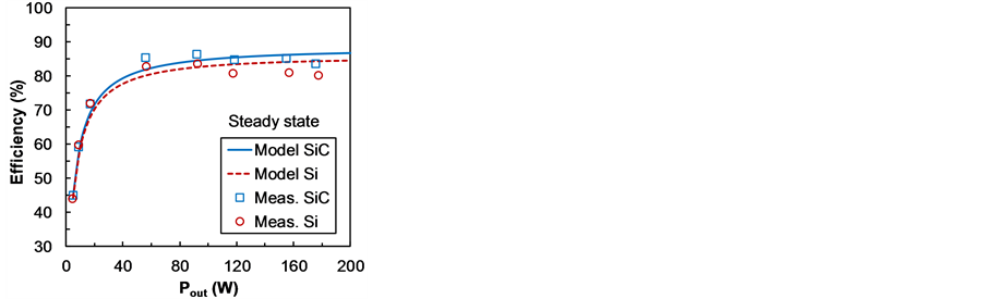
Figure 6. Modeled (lines) and measured (symbols) conversion efficiencies of SiC- and Si-based inverters with respect to output power.

Figure 7. Dependence of DC-AC converter loss on the output power of the (a) SiC- and (b) Si-based inverters. DC-DC converter losses and non-load losses are not included.
(a) 5, (b) 10, (c) 20, (d) 50, (e) 100, and (f) 200 W. DC-DC converter losses and non-load losses are not shown. The main power loss components in these inverters were the switching loss (Pon and Poff) and reverse recovery loss (Prr). Decreases in these loss elements were responsible for the 2% improvement in efficiency of the SiC-based inverter. The contribution from conduction loss was more significant at higher output power. However, this calculation suggested that the loss improvement due to the small Rds in a SiC MOSFET would be negated by the loss enhancement due to the large Vf of the body diode.
The main application of SiC power devices is multi-kW level converters. A 100-W class converter cannot fully benefit from the low ON resistance of SiC devices. However, the switching and reverse recovery losses were still improved in the SiC-converter, as shown in Figure 8, which has yielded the 3% improvement of the DC-AC conversion efficiency in the present 100-W class inverter.
The SiC inverter was prepared by replacing the Si MOSFETs in a conventional Si inverter with SiC MOSFETs, but the overall circuit remained optimized for Si MOSFETs. The switching frequency was also set to that of the conventional Si-inverter value. The switching frequency is related to the electric waveforms that are controlled by the filter circuit. Thus, simply replacing Si devices with SiC devices is far from an optimal design. In spite of this, the SiC inverter exhibited an efficiency superior to that of the conventional Si inverter. Optimizing the circuit is likely to further improve performance. We are currently engaged in redesigning the inverter circuit, the results of which will be reported elsewhere.
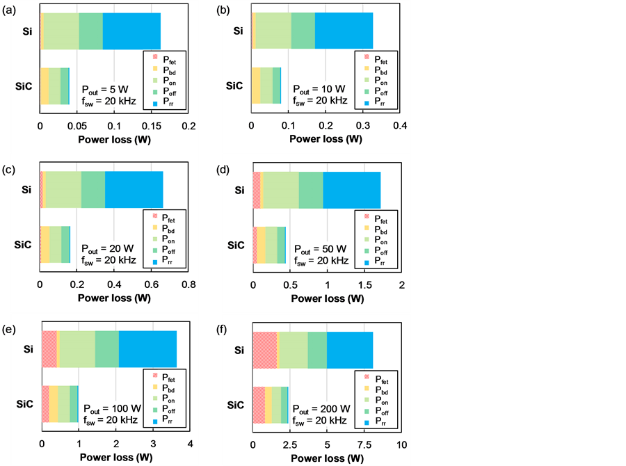
Figure 8. Contribution of power loss elements (FET conduction loss Pfet, BD conduction loss Pbd, turn-on loss Pon, turn-off loss Poff, and reverse recovery loss Prr) in SiC- and Si-based DC-AC converters occurring at output powers of (a) 5, (b) 10, (c) 20, (d) 50, (e) 100, and (f) 200 W. DC-DC converter losses and non-load losses are not shown.
5. Conclusion
We developed 100-W class power storage systems composed of spherical Si solar cells, an MPPT controller, a Li-ion battery, and one of two types of DC-AC converters. One inverter used SiC MOSFETs as switching devices while the other used Si MOSFETs. Although the circuit was not optimized for the SiC MOSFETs, the SiC-based inverter exhibited a superior DC-AC conversion efficiency compared with the conventional Si-based inverter. Power loss analysis indicated that the ON resistance had little influence on the efficiency, and that a reduction in switching and recovery losses was responsible for the higher efficiency of the SiC-based inverter. These results demonstrate the feasibility of SiC MOSFETs even for 100-W class photovoltaic power generation systems.
Acknowledgements
This study was supported by the Super Cluster Program of the Japan Science and Technology Agency (JST).
Cite this paper
Ando, Y., Shirahata, Y., Oku, T., Matsumoto, T., Ohishi, Y., Yasuda, M., Shimono, A., Takeda, Y. and Murozono, M. (2017) Comparison between SiC- and Si-Based Inverters for Photovoltaic Power Generation Systems. Journal of Power and Energy Engineering, 5, 30-40. http://dx.doi.org/10.4236/jpee.2017.51003
References
- 1. Labedev, A.A. and CHelnokov, V.E. (1999) Wide-Gap Semiconductors for High- Power Electronics. Semiconductors, 33, 999-1001. https://doi.org/10.1134/1.1187823
- 2. Monroy, E., Omnès, F. and Calle, F. (2003) Wide-Bandgap Semiconductor Ultraviolet Photodetectors. Semiconductor Science and Technology, 18, R33-R51. https://doi.org/10.1088/0268-1242/18/4/201
- 3. Okumura, H. (2006) Present Status and Future Prospect of Widegap Semiconductor High-Power Devices. Japanese Journal of Applied Physics, 45, 7565-7586. https://doi.org/10.1143/JJAP.45.7565
- 4. Burger, B., Kranzer, D. and Stalter, O. (2008) Cost Reduction of PV-Inverters with SiC-DMOSFETs. Proceedings of the 2008 5th International Conference on Integrated Power Electronics Systems (CIPS 2008), Nuremberg, Germany, 11-13 March 2008, 1-5.
- 5. Chinthavali, M., Zhang, H., Tolbert, L.M. and Ozpineci, B. (2009) Update on SiC- Based Inverter Technology. Proceedings of the 2009 Brazilian Power Electronics Conference (COBEP 2009), Bonito-Mato Grosso do Sul, Brazil, 27 September-1 October 2009, 71-79. https://doi.org/10.1109/cobep.2009.5347590
- 6. Hensel, A., Wilhelm, C. and Kranzer, D. (2011) Development of a Boost Converter for PV Systems Based on SiC BJTs. Proceedings of the 2011 14th European Conference on Power Electronics and Applications (EPE 2011), Birmingham, U.K., 30 August-1 September 2011, 1-7.
- 7. De, D., Castellazzi, A. Solomon, A., Trentin A., Minami, M. and Hikihara, T. (2013) An All SiC MOSFET High Performance PV Converter Cell. Proceedings of the 2013 15th European Conference on Power Electronics and Applications (EPE 2013), Lille, France, 2-6 September 2013, 1-10. https://doi.org/10.1109/EPE.2013.6634642
- 8. Yamane, A., Koyanagi, K., Kozako, M., Fuji, K. and Hikita, M. (2013) Fabrication and Evaluation of SiC Inverter Using SiC-MOSFET. IEEE 10th International Conference of Power Electronics and Drive Systems (PEDS 2013), Kitakyushu, Japan, 22-25 April 2013, 1029-1032. https://doi.org/10.1109/PEDS.2013.6527171
- 9. Li, L., Li, C., Cao, Y. and Wang, F. (2013) Recent Progress of SiC Power Devices and Applications. IEEJ Transactions on Electrical and Electronic Engineering, 8, 515- 521. https://doi.org/10.1002/tee.21888
- 10. Kim, T., Jang, M. and Agelidis, V.G. (2013) Current Status of Silicon Carbide Power Devices and Their Application in Photovoltaic Converters. 2013 IEEE ECCE Asia Downunder (ECCE Asia), Melbourne, Australia, 3-6 June 2013, 555-559. https://doi.org/10.1109/ECCE-Asia.2013.6579152
- 11. Nashida, N., Hinata, Y., Horio, M., Yamada, R. and Ikeda, Y. (2014) All-SiC Power Module for Photovoltaic Power Conditioner System. IEEE 26th International Symposium of Power Semiconductor Devices & IC’s (ISPSD 2014), Waikoloa, HI, 15-19 June 2014, 342-345. https://doi.org/10.1109/ISPSD.2014.6856046
- 12. Burkart, R.M. and Kolar, J.W. (2013) Comparative Evaluation of SiC and Si PV Inverter Systems Based on Power Density and Efficiency as Indicators of Initial Cost and Operating Revenue. 2013 IEEE 14th Workshop on Control and Modeling for Power Electronics (COMPEL), Salt Lake City, UT, 23-26 June 2013, 1-6. https://doi.org/10.1109/COMPEL.2013.6626462
- 13. Sintamarean, C., Blaabjerg, F. and Wang, H. (2013) Comprehensive Evaluation on Efficiency and Thermal Loading of Associated Si and SiC Based PV Inverter Applications. IECON 2013—39th Annual Conference of the IEEE Industrial Electronics Society Vienna, Austria, 10-13 November 2013, 555-560.
- 14. Oku, T., Kanayama, M., Ono, Y., Akiyama, T., Kanamori, Y. and Murozono, M. (2014) Microstructures, Optical and Photoelectric Conversion Properties of Spherical Silicon Solar Cells with Anti-Reflection SnOx:F Thin Films. Japanese Journal of Applied Physics, 53, 05FJ03-1-7. https://doi.org/10.7567/jjap.53.05fj03
- 15. Oku, T., Matsumoto, T., Hiramatsu, K., Yasuda, M., Shimono, A., Takeda, Y. and Murozono, M. (2015) Construction and Characterization of Spherical Si Solar Cells Combined with SiC Electric Power Inverter. AIP Conference Proceedings, 1649, 79-83. https://doi.org/10.1063/1.4913548
- 16. Matsumoto, T., Oku, T., Hiramatsu, K., Yasuda, M., Shirahata, Y., Shimono, A., Takeda, Y. and Murozono, M. (2016) Evaluation of Photovoltaic Power Generation System Using Spherical Silicon Solar Cells and SiC-FET Inverter. AIP Conference Proceedings, 1709, 020023-1-6. https://doi.org/10.1063/1.4941222
- 17. Oku, T., Matsumoto, T., Hiramatsu, K., Yasuda, M., Ohishi, Y., Shimono, A., Takeda, Y. and Murozono, M. (2016) Construction and Evaluation of Photovoltaic Power Generation and Power Storage System Using SiC Field-Effect Transistor Inverter. AIP Conference Proceedings, 1709, 020024-1-10.
- 18. Fairchild Semiconductor (2013) Datasheet of FQPF16N25C—N-Channel QFET MOSFET.
- 19. ROHM Semiconductor (2015) Datasheet of SCT2120AF—N-Channel SiC Power MOSFET.
- 20. Pattnaik, S.K. and Mahapatra, K.K. (2010) Power Loss Estimation for PWM and Soft-Switching Inverter Using RDCLI. Proceedings of the International MultiConference of Engineers and Computer Scientists 2010 (IMECS 2010), Hong Kong, 17-19 March 2010, 1401-1406.
- 21. ROHM Semiconductor (2014) SiC Power Devices and Modules—Application Note. http://rohmfs.rohm.com/en/products/databook/applinote/discrete/sic/common/sic_appli-e.pdf