Journal of Power and Energy Engineering
Vol.2 No.7(2014), Article
ID:47932,9
pages
DOI:10.4236/jpee.2014.27003
Phasor Control of Converter Output Voltage for Frequency Regulation
Masahide Hojo1, Ryo Ikeshita1, Yoshinobu Ueda2, Toshihisa Funabashi3
1Institute of Technology and Science, The University of Tokushima, Tokushima, Japan
2Power Utility Sector Business Unit, Meidensha Corporation, Tokyo, Japan
3EcoTopia Science Institute, Nagoya University, Nagoya, Japan
Email: hojo@ee.tokushima-u.ac.jp
Copyright © 2014 by authors and Scientific Research Publishing Inc.
This work is licensed under the Creative Commons Attribution International License (CC BY).
http://creativecommons.org/licenses/by/4.0/


Received 28 May 2014; revised 30 June 2014; accepted 8 July 2014
ABSTRACT
The synchronizing torque of a power system may be weakened by increasing installation of static power converters accompanied by renewable energy resources because they used to trade their favorable active power by synchronizing their output voltage with the one at the point of common coupling. In the circumstances, a concept of Virtual Synchronous Machine (VSM) is proposed, where the self-commutated power converters are emulating synchronous generators. This paper describes a converter control to contribute to enhancing the synchronizing torque. The proposed control is similar to the VSM but it simply realizes active power trades among power generation units including converter-based generators by modulating phase angles of their output voltages. Therefore, it can provide an effective support to regulate the system frequency where the total rated power of the converter-based generators increases as much as the one of conventional rotating generators like a microgrid. This paper especially focuses on its robustness where the number of converter-based generators is increased or they are dispersed in the power network. The effectiveness is verified by simulation study based on instantaneous values.
Keywords:Self-Commutated Power Converter, Synchronous Generator, Frequency Control, Voltage Phasor

1. Introduction
A conventional power system has been supplied by a lot of synchronous generators. They have kept a good power balance among them by their synchronizing torques. On the other hand, a distributed generator injects its maximum output power by observing the phase angle of the voltages at its coupling point. The power balance can be kept successfully while the total amount of power generated by the distributed generators is negligible compared to the synchronous generators.
Today, the synchronizing torque of a power system may be weakened by increasing installation of static power converters accompanied by renewable energy resources with a growing demand of high penetration of renewable energies. In a microgrid, batteries are often installed with the renewable energy resources to compensate their fluctuating output power. As a result, a lot of static power converters will be normally installed with traditional synchronous generators. In case that the total rated power of the converters exceeds the one of synchronous generators, it is afraid that the synchronizing torque of the microgrid may be spoiled. In the circumstances, there is a proposal of a Virtual Synchronous Machine (VSM) [1] -[3] , where the converter behaves like a traditional synchronous machine with the inertia. In recent literatures, the effectiveness of the VSM is evaluated as compared to the traditional droop controller [4] and its dynamic performance is also analyzed [5] . Assuming that the converter is supported by an ideal dc voltage source and consists of ideal semiconductor devices, the VSM can be realized to be equipped with a swing equation onto its controller. The effectiveness is promised by the designed swing equation under an assumed system condition. However, it may be difficult to achieve the same effect when the power system condition is continuously modified according to the increasing installation of the renewable energy resources.
In the circumstances, unlike the VSM, authors proposed a phase-shifting method of the output voltage phasor [6] , which simply only emulates an active power exchange between the power converter and the power system to enhance the synchronizing torque of the power system. In the traditional converter control, the output voltage phasor is determined to be synchronized with the terminal voltage at the point of common coupling as described above. On the other hand, the infinite bus voltage can be considered as a voltage phasor with the frequency fixed to its rated value. In the proposed control strategy, each converter independently determines its output voltage phase angle between the two phasors using single control gain and the amplitude of the output voltage is decided by a reactive power control in order to reduce inverter output currents. The control gain can regulate its contribution level, according to its surplus capacity of the converter or energy storage. This is the reasons why the proposed control can be an autonomous control system and it has robustness where the converters continue to be installed increasingly. Therefore, it can provide an effective support to regulate the system frequency where the total rated power of the converter-based generators increases as much as one of the conventional rotating generators like a microgrid.
However, it can be hardly estimated where the available converters are installed and how many inverters join the frequency regulation. Therefore, such control strategy is required to be useful under uncertain conditions. In the proposed control, each converter can share the task automatically in accordance with the electrical distance among the generation units and, if it is overtasked, it can reduce the task by modulating the control gain. This paper explains the behaviors of multiple power converters equipped with the proposed control and verifies its operating characteristics discussed above by simulation study based on instantaneous values. Especially, it is confirmed that multiple static power converters employing the proposed controller can properly cooperate with each other when they are distributed or they use other control parameters.
2. Converter Control for Cooperation with a Synchronous Generator
2.1. Phase Angle Regulation for Active Power Control
In order to consider an active power interaction between a synchronous generator and a static power converter, a simple system model is used in this paper, as shown in Figure 1. For the simplicity, the synchronous generators and the converters are represented by single ones, respectively. ![]() and
and ![]() represent the fundamental components of terminal voltages at the synchronous generator and the converter and their phase angles are represented by
represent the fundamental components of terminal voltages at the synchronous generator and the converter and their phase angles are represented by ![]() and
and , respectively. The terminal voltage of the synchronous generator is regulated by a traditional Automatic Voltage Regulator equipped with the generator.
Generally, the self-commutated static power converter regulates its output voltage based on the phase angle of the terminal voltage at the point of common coupling. It detects the phase angle of the terminal voltage at the coupling point  and decides its output voltage. Therefore, the converter follows the frequency regulated by the synchronous generator and trades its favorable output power. Assume that the initial value of the converter phase angle is
 , the converter phase angle
  can be determined as:
 , (1)
, (1)
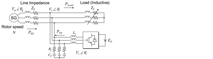
Figure 1. A model with a synchronous generator and a selfcommutated static power converter.
where ![]() is the angular velocity of the synchronous generator. In this case, the converter can be considered as a synchronous machine whose inertia is zero.
is the angular velocity of the synchronous generator. In this case, the converter can be considered as a synchronous machine whose inertia is zero.
On the other hand, the infinite bus has an infinite inertia and a constant voltage. If there is an ideal self-commutated converter with an ideal energy source, it can realize the infinite bus and it is quite stable all through the operation of the microgrid. In this case, the converter phase angle can be represented by the nominal value of the angular velocity , as
, as
 . (2)
. (2)
The synchronous generators trade their power after a disturbance and keep a stable cooperation in a power system. The power trade is realized by the difference of the phase angle between them. From this viewpoint, the power trade can be realized by modulating the phase angle of the converter.
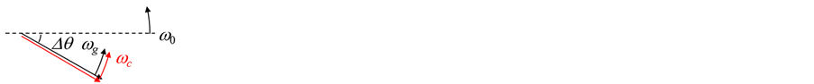
Figure 2 summarizes relationships among voltage phasors. Assume that a small disturbance makes the phase angle of the synchronous generator ![]() lag behind the reference angle
lag behind the reference angle ![]() by
by![]() . When the converter is operated in the traditional operating mode, the voltage phasors can be indicated as Figure 2(a). On the other hand, the converter is operated as shown in Figure 2(b) in case that the converter acts as an infinite bus voltage. Therefore, this paper proposes that the output voltage phasor is placed as shown in Figure 2(c), in order enhance the synchronizing torque of the power system.
. When the converter is operated in the traditional operating mode, the voltage phasors can be indicated as Figure 2(a). On the other hand, the converter is operated as shown in Figure 2(b) in case that the converter acts as an infinite bus voltage. Therefore, this paper proposes that the output voltage phasor is placed as shown in Figure 2(c), in order enhance the synchronizing torque of the power system.
To set the voltage phasor as shown in Figure 2(c), the converter phase angle  is determined as
 , (3)
, (3)
 . (4)
. (4)
The phase angle of the converter  can be increased to lead
 ![]() by
by ![]() as shown in Figure 2(d). In this case, the angular velocities can be formulated by
as shown in Figure 2(d). In this case, the angular velocities can be formulated by
 . (5)
. (5)
Therefore, the phase angle  can be derived as
 . (6)
. (6)
However, Equation (6) can be represented by substituting 2.0 to  of Equation (3). Therefore, all operating modes can be represented as Figure 2 with different value of
![]() .
.
2.2. Amplitude Modification for Reactive Power Control
In order to reduce the converter rated current, reducing the reactive power output is effective. Therefore, the voltage phasor amplitude is regulated in addition to the phase angle control.
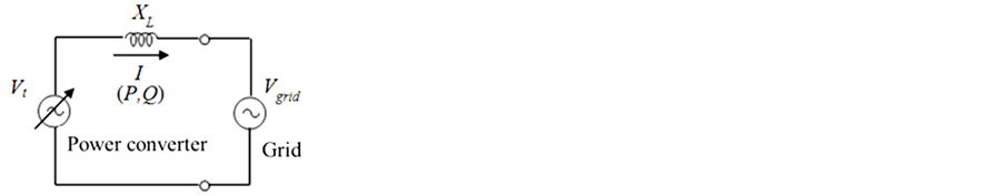
Figure 3(a) is a simple equivalent circuit when a self-commutated power converter is interconnected to a power system with a linkage inductance![]() .
.  represents the output voltage of the converter and
 ![]() is the voltage at the coupling point. By the phase angle difference
is the voltage at the coupling point. By the phase angle difference ![]() between
between  and
and![]() , voltage phasors can be indicated as shown in Figure 3(b). In this case, the converter trades active and reactive power as:
, voltage phasors can be indicated as shown in Figure 3(b). In this case, the converter trades active and reactive power as:
 (a)
(a)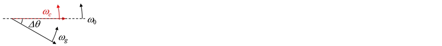 (b)
(b) (c)
(c) (d)
(d)
Figure 2. Various placements of the converter output voltage phasors. (a) kc = 0.0, (b) kc = 1.0, (c) 0.0 < kc < 1.0, (d) kc = 2.0.
 (a)
(a) (b)
(b)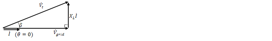 (c)
(c)
Figure 3. Reactive power regulation of the converter. (a) A simplified equivalent circuit, (b) Phase-shifted output voltage phasors, (c) Regulated output voltage phasor.
![]() , (7)
, (7)
![]() . (8)
. (8)
Considering the relations among the voltage phasors as shown in Figure 3(b),
 , (9)
, (9)
![]() . (10)
. (10)
Therefore, the active and reactive power can be formulated as
 , (11)
 . (12)
Assumed that the reactive power ![]() is equal to zero, the following equation can be derived from Equation (12);
is equal to zero, the following equation can be derived from Equation (12);
 . (13)
By detecting the phase angle of the voltage![]() ,
, ![]() can be achieved. Then, the reactive power can be equal to zero by keeping the relation of Equation (13).
can be achieved. Then, the reactive power can be equal to zero by keeping the relation of Equation (13).
2.3. Proposed Voltage Phasor Controller
The output voltage controller consists of the above two concept as shown in Figure 4. First, the phase angle of the voltage is determined and then its amplitude is modified based on the reactive power control. The proposed control is equipped with a sinusoidal wave generator and the well-known triangular-wave Pulse Width Modulation of a three-phase voltage sourced converter, as shown in Figure 4.
It should be noted that the reference angle is ordinary determined by the traditional method such as normal PLL. When the converter controller detects a large frequency variation beyond its prescribed threshold value, the proposed controller slightly shift its reference angle by this method.

Figure 4. Output voltage controller of the converter.
3. Simulation Results with Single Inverter Unit
The proposed control is verified by simulation study. A system model shown in Figure 1 is used with the parameters summarized in Table1 The dc side voltage of the converter is assumed to be supported by ideal dc voltage source. On the other hand, the traditional rotating synchronous machine is represented by a Motor-andGenerator combination which employs a speed governor and an automatic voltage regulator.
In the actual system, it may be difficult to detect the frequency of the center of inertia. For the simplicity, the referential frequency is assumed to be detected by the rotor speed of the rotating generator in this paper.
When , Figure 5 shows how the frequency and active power output of synchronous generator and power converter behaves after the load variation. It can be confirmed in the upper figures that the controller set the frequency reference as a half of system frequency.
If the control gain is adjusted, the effectiveness of the controller can be modified as shown in Figure 6. When , the active power output of the converter immediately recovered to the initial value and it does not contribute the frequency regulation. However, increasing
  enhances the control effect as shown in Figure 6.
From these results, the proposed controller can adjust its control effect by simply modifying the single control gain .
.
4. Control Effect by Multiple Converters
When the proposed controller is applied to multiple power converters, their parameters can be designed independently. Figure 7 shows a model system with two power converters which are equipped with the proposed control. The control gains  and
and  are defined to adjust their contributions to frequency regulation. Table 2 summarizes simulation conditions.
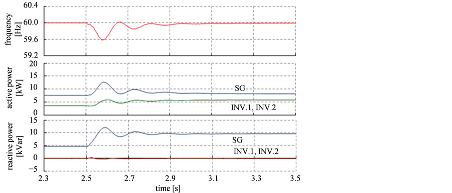
First, same circuit parameters are given to the two converters, which are indicated as the Case 1 in Table 2, but different control gains  and
and  are applied to them. Figure 8 displays simulation results, comparing with the different control gains. As shown in Figure 8(a), same control gains result in the same behaviors, where the same active powers are injected and both reactive powers are regulated as zero.
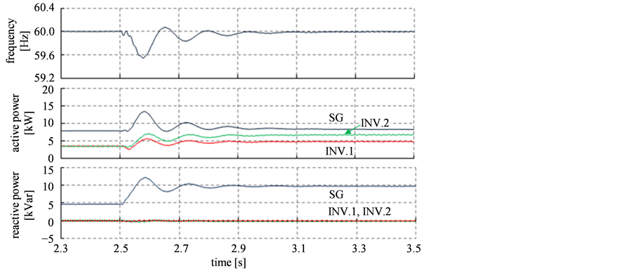
On the other hand, different control gains introduce different behaviors as shown in Figure 8(b). There is no difference in the frequency variations of the two cases because the values of  are same. However, two converters show different contributions after the load variation. The converter 2 with the larger control gain output high active power, resulting in the high contributions to the frequency regulation.
Therefore, it is confirmed that the contribution to the frequency regulation can be simply adjusted by the control gain.
Figure 9 shows simulation results in Case 2, where the different circuit parameters are used as indicated in Table2 The different linkage inductance implies that they are not installed at the same point but distributed in a power network. However, as the proposed control directly modifies the phase angle of the output voltage of the converter, the output active power is influenced by the interconnecting inductance. Therefore, although the same control gains are used in the proposed controller in the case of Figure 9(a), the output active power of the converter 2 is larger than the one of the converter 1. In addition, if the control gain of the converter 2 is changed to the larger one, the output active power is increased as shown in Figure 9(b).
The two converters are connected at the same coupling point as indicated in Figure 7, but the interconnecting inductance means the electrical distance from the coupling point. Therefore, Figure 9(a) also indicates that the converter which is near the generator contributes well to the frequency regulation.
5. Conclusion
This paper proposed a simple converter controller to contribute to the system frequency regulation. The converter control emulating the power trade between the synchronous machines is developed and equipped to the static

Table 1 . Conditions for simulation study.
Table 2. Conditions for simulation with two converters.

Figure 5. Frequency and active powers after a load variation when kc = 0.5.
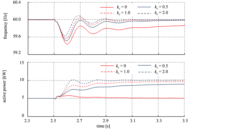
Figure 6. Comparisons of frequency and active powers with different gain kc.
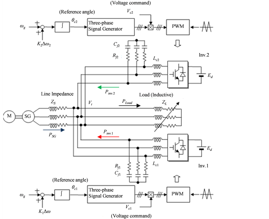
Figure 7. System model with two converter system.
 (a)
(a)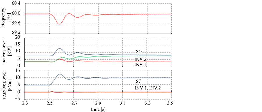 (b)
(b)
Figure 8. Simulation results when the same linkage inductances and filter capactors are used (Case 1). (a) K1 = K2 = 1/2, (b) K1 = 1/4, K2 = 3/4.
 (a)
(a)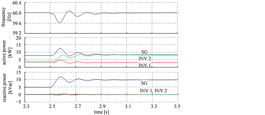 (b)
(b)
Figure 9. Simulation results when different linkage inductances and filter capactors are used (Case 2). (a) K1 = K2 = 1/2, (b) K1 = 1/4, K2 = 3/4.
power converter. The effectiveness of the controller is tested by simulation study in case of a small disturbance like a load variation. In the simulation study, it is confirmed that the contribution of the converter can be easily adjusted by the single control gain. In addition, the controller can be also tested when multiple converters employ it. By the detailed simulation, the two converters share the role of the frequency regulation, according to their control gains or the electrical distance among the generation units. From these results, the proposed controller can be easily applied to the power converter such as being used for renewable energy resources with some amount of energy storage, resulting in enhancement of frequency regulations.
Acknowledgements
This work was supported by Grant-in-Aid for Scientific Research (C) of Japan Society for the Promotion of Science (JSPS), as JSPS KAKENHI Grant Number 25420258.
References
- Beck, H.P. and Hesse, R. (2007) Virtual Synchronous Machine. International Conference on Electrical Power Quality and Utilization, Barcelona, 9-11 October 2007, 6 p.
- Visscher, K. and Haan, S.W.H. (2008) Virtual Synchronous Machines (VSG’s) for Frequency Stabilization in Future Grids with a Significant Share of Decentralized Generation. CIRED Seminar 2008: Smart-Grids for Distribution, Frankfurt, 23-24 June 2008, 0118.
- Sakimoto, K., Sugimoto, K. and Shindo, Y. (2013) Low Voltage Ride through Capability of a Grid Connected Inverter Based on the Virtual Synchronous Generator. Proceedings of the IEEE 10th International Conference on Power Electronics and Drive Systems, Kitakyushu, 22-25 April 2013, 1066-1071.
- Alipoor, J., Miura, Y. and Ise, T. (2014) Voltage Sag Ride-Through Performance of Virtual Synchronous Generator. Proceedings of the 2014 International Power Electronics Conference—ECCE, Hiroshima, 18-21 May 2014, 3298-3305.
- Liu, J., Miura, Y. and Ise, T. (2014) Dynamic Characteristics and Stability Comparisons between Virtual Synchronous Generator and Droop Control in Inverter-Based Distributed Generators. Proceedings of the 2014 International Power Electronics Conference—ECCE, Hiroshima, 18-21 May 2014, 1536-1543.
- Hojo, M., Ikeshita, R., Terauchi, T., Ueda, Y. and Funabashi, T. (2011) A Converter Controller of Virtual Synchronous Machine for Stable Operation of Microgrid. Conference Proceedings of 21th International Conference and Exhibition on Electricity Distribution (CIRED), Frankfurt, 6-9 June 2011, 0535.