Journal of Computer and Communications
Vol.06 No.09(2018), Article ID:87177,15 pages
10.4236/jcc.2018.69003
An Efficient Acceleration of Solving Heat and Mass Transfer Equations with the Second Kind Boundary Conditions in Capillary Porous Composite Cylinder Using Programmable Graphics Hardware
Hira Narang, Fan Wu, Abdul Rafae Mohammed
Computer Science Department, Tuskegee University, Tuskegee, AL, USA

Copyright © 2018 by authors and Scientific Research Publishing Inc.
This work is licensed under the Creative Commons Attribution-NonCommercial International License (CC BY-NC 4.0).
http://creativecommons.org/licenses/by-nc/4.0/


Received: February 21, 2018; Accepted: September 4, 2018; Published: September 7, 2018
ABSTRACT
With the recent developments in computing technology, increased efforts have gone into simulation of various scientific methods and phenomenon in engineering fields. One such case is the simulation of heat and mass transfer in capillary porous media, which is becoming more and more important in analysing various scenarios in engineering applications. Analysing such heat and mass transfer phenomenon in a given environment requires us to simulate it. This entails simulation of coupled heat mass transfer equations. However, this process of numerical solution of heat and mass transfer equations is very much time consuming. Therefore, this paper aims at utilizing one of the acceleration techniques developed in the graphics community that exploits a graphics processing unit (GPU) which is applied to the numerical solutions of heat and mass transfer equations. The nVidia Compute Unified Device Architecture (CUDA) programming model caters a good method of applying parallel computing to program the graphical processing unit. This paper shows a good improvement in the performance while solving the heat and mass transfer equations for capillary porous composite cylinder with the second kind of boundary conditions numerically running on GPU. This heat and mass transfer simulation is implemented using CUDA platform on nVidia Quadro FX 4800 graphics card. Our experimental results depict the drastic performance improvement when GPU is used to perform heat and mass transfer simulation. GPU can significantly accelerate the performance with a maximum observed speedup of more than 7-fold times. Therefore, the GPU is a good approach to accelerate the heat and mass transfer simulation.
Keywords:
Numerical Solution, Heat and Mass Transfer, General Purpose Graphics Processing Unit (GPGPU), CUDA

1. Introduction
During the last half century, many scientists and engineers working in Heat and Mass Transfer processes have put lots of efforts in finding solutions both analytically/numerically, and experimentally. To precisely analyze physical behaviors of heat and mass environment, to simulate several heat and mass transfer phenomena such as heat conduction, convection, and radiation are very important. A heat transfer simulation is accomplished by utilizing parallel computer resources to simulate such heat and mass transfer phenomena. With the helps from computer, initially the sequential solutions were found, and later when high-end computers became available, fast solutions were obtained to heat and mass transfer problems. However, the heat and mass transfer simulation requires much more computing resources than the other simulations. Therefore, acceleration of this simulation is very essential to implement a practical big data size heat and mass transfer simulation.
This paper utilizes the parallel computing power of GPUs to speed up the heat and mass transfer simulation. GPUs are very efficient considering theoretical peak floating-point operation rates [1] . Therefore, comparing with super-computer, GPUs is a powerful co-processor on a common PC which is ready to simulate a large-scale heat and mass transfer at a less resources. The GPU has several advantages over CPU architectures, such as highly parallel, computation intensive workloads, including higher bandwidth, higher floating-point throughput. The GPU can be an attractive alternative to clusters or super-computer in high performance computing areas.
CUDA [2] by NVidia already proved its effort to develop both programming and memory models. CUDA is a new parallel, C-like language programming Application program interface (API), which bypasses the rendering interface and avoids the difficulties from using GPGPU. Parallel computations are expressed as general-purpose, C-like language kernels operating in parallel over all the points in an application.
This paper develops the numerical solutions to Two-point Initial-Boundary Value Problems (TIBVP) of Heat and Mass with the second kind boundary conditions in capillary porous composite cylinder. These problems can be found some applications in drying processes, space science, absorption of nutrients, transpiration cooling of space vehicles at re-entry phase, and many other scientific and engineering problems. Although some traditional approaches of parallel processing to the solutions of some of these problems have been investigated, no one seems to have explored the high performance computing solutions to heat and mass transfer problems with compact multi-processing capabilities of GPU, which integrates multi-processors on a chip. With the advantages of this compact technology, we developed algorithms to find the solution of TIBVP with the second kind boundary conditions and compare with some existing solutions to the same problems. All of our experimental results show significant performance speedups. The maximum observed speedups are about 10 times.
The rest of the paper is organized as follow: Section II briefly introduces some closely related work; Section III describes the basic information on GPU and CUDA; Section IV presents the mathematical model of heat and mass transfer and numerical solutions to heat and mass transfer equations; Section V presents our experimental results; And Section VI concludes this paper and give some possible future work directions.
2. Related Work
The simulation of heat and mass transfer has been a very hot topic for many years. And there is lots of work related to this field, such as fluid and air flow simulation. We just refer to some most recent work close to this field here.
Soviet Union was one time in the fore-front for exploring the coupled Heat and Mass Transfer in porous media, and major advances were made at Heat and Mass Transfer Institute at Minsk, BSSR [3] . Later England and India took the lead and made further contributions for analytical and numerical solutions to certain problems. Narang [4] - [9] explored the wavelet solutions to heat and mass transfer equations and Ambethkar [10] explored the numerical solutions to some of these problems.
Krüger et al. [11] computed the basic linear algebra problems with the feathers of programmability of fragments on GPU, and further computed the 2D wavelets equations and NSEs on GPU. Bolz et al. [12] matched the sparse matrix into textures on GPU, and utilized the multigrid method to solve the fluid problem. In the meantime, Goodnight et al. [13] used the multigrid method to solve the two-point boundary value problems on GPU. Harris [14] [15] solved the Partial Differential Equation (PDE) of dynamic fluid motion to get cloud animation.
GPU has also been used to solve other kinds of PDE’s by other researchers. Kim et al. [16] solved the crystal formation equations on GPU. Lefohn et al. [17] matched the level-set iso-surface data into a dynamic sparse texture format. Another creative usage has been to pack the information of the next active tiles into a vector message, which was used to control the vertices and texture coordinates needed to send from CPU to GPU. To learn more applications about general-purpose computations with GPU, more information can be found from here [18] . The applications of the heat and mass transfer in capillary porous hollow cylinders is studied by Narang and his associates first time in [19] [20] , under various environmental conditions.
3. An Overview of CUDA Architecture
The GPU that we have used in our implementations is nVidia’s Quadro FX 4800, which is DirectX 10 compliant. It is one of nVidia’s fastest processors that support the CUDA API and as such all implementations using this API are forward compatible with newer CUDA compliant devices. All CUDA compatible devices support 32-bit integer processing. An important consideration for GPU performance is its level of occupancy. Occupancy refers to the number of threads available for execution at any one time. It is normally desirable to have a high level of occupancy as it facilitates the hiding of memory latency.
The GPU memory architecture is shown in Figure 1.
4. Mathematical Model and Numerical Solutions of Heat and Mass Transfer
This consists of two sections, with first section is devoted to modelling, and second section to its numerical solution.
4.1. Mathematical Model
Consider the Heat and Mass Transfer through a capillary porous composite cylinder with boundary conditions of the second kind. Let the z-axis be directed upward along the capillary porous composite cylinder and the r-axis radius of the capillary porous composite cylinder. Let u and v be the velocity components along the z- and r-axes respectively. We write separate equations for each material as both will have different properties.
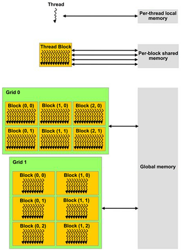
Figure 1. GPU memory architecture [2] .
Since we are concerned about studying the effect of conductivities of the 2 materials we observe their behaviour under the same initial and boundary conditions. So the first equation will correspond to the first material (0 < z < L) whereas the second equation correspond to the second material with different heat and mass constants (L < z < 2L). Then the heat and mass transfer equations in the Boussinesq’s approximation, are:
For capillary porous composite cylinder:
(1)
(2)
where L is the Length of the first material
*
(1a)
(2a)
where L is the Length of the Second material
*
Initial Conditions:
(3)
Boundary Conditions z = 0, 1 are:
(4)
(5)
The boundary conditions on the circular boundary r = 1:
(7)
(8)
Since the composite cylinder is assumed to be capillary porous, is the velocity of the fluid, the temperature of the fluid near the capillary porous composite cylinder, the temperature of the fluid far away from the capillary porous composite cylinder, the concentration near the capillary porous composite cylinder, the concentration far end of the capillary porous composite cylinder, g the acceleration due to gravity, the coefficient of volume expansion for heat transfer, the coefficient of volume expansion for concentration, the kinematic viscosity, the scalar electrical conductivity, the frequency of oscillation, k the thermal conductivity.
From Equation (1) we observe that is independent of space co-ordinates and may be taken as constant. We define the following non-dimensional variables and parameters.
(9)
(10)
Now taking into account Equations (5)-(8), Equation (1) and Equation (2) reduce to the following form:
(11)
(12)
(13)
(14)
4.2. Numerical Solution
Here we sought a solution by finite difference technique of implicit type namely Crank-Nicolson implicit finite difference method which is always convergent and stable. This method has been used to solve Equation (8), and Equation (9) subject to the conditions given by (4), (5) and (6). To obtain the difference equations, the region of the heat is divided into a gird or mesh of lines parallel to z and r axes. Solutions of difference equations are obtained at the intersection of these mesh lines called nodes. The values of the dependent variables T, and C at the nodal points along the plane are given by and hence are known from the boundary conditions.
In Figure 2, & are constant mesh sizes along z and r directions respectively. We need an algorithm to find single values at next time level in terms of known values at an earlier time level. A forward difference approximation for the first order partial derivatives of T and C. And a central difference approximation for the second order partial derivative of T and C are used. On introducing finite difference approximations for:
For the purposes of coming up with a numerical solution for the problem, the radius of the capillary porous composite cylinder is 1.0. The partial derivatives are approximated by following formulas:
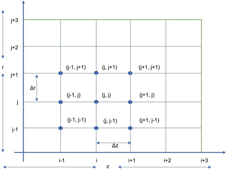
Figure 2. Finite difference grid for capillary porous composite cylinder.
The finite difference approximation of Equation (8) and Equation (9) are obtained with substituting Equation into Equation (8) and Equation (9) and
multiplying both sides by and after simplifying, we let
(method is always stable and convergent), under this condition the above equations can be written as:
Let
Let
4.3. Grid Structure and Heat Continuity Condition
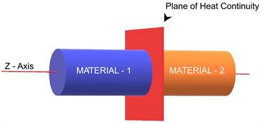
The plane of heat continuity is the plane along the radial axis of the solid composite cylinder (as shown in Figure 3(a)) where the material properties change i.e. where the two different materials are joined or merged together. So, the grid position in the above composite cylinder is as depicted in Figure 3(b).
 (a)
(a)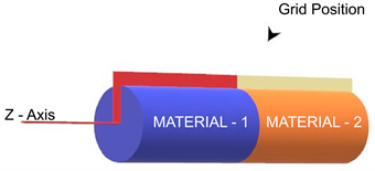 (b)
(b)
Figure 3. (a) Plane of heat continuity in a composite solid cylinder; (b) Grid position in a composite solid cylinder.
At this point of intersection, i.e. the plane of heat continuity, when the heat transfer occurs, the temperature at the last grid point along any radius of the first material is approximately equal to the temperature at the first grid point in the second material. Similarly, the concentration at the last grid point along any radius of the first material is approximately equal to the concentration at the first grid point in the second material. So, the heat continuity equation can be written as follows:
(15)
(16)
(17)
(18)
5. Experimental Results and Discussion
This is discussed under two sections, one which discusses the setup and device configuration and the other, experimental results.
5.1. Setup and Device Configuration
The experiment was executed using the CUDA Runtime Library, Quadro FX 4800 graphics card, Intel Core 2 Duo. The programming interface used was Visual Studio. The experiments were performed using a 64-bit Lenovo Think Station D20 with an Intel Xeon CPU E5520 with processor speed of 2.27 GHZ and physical RAM of 4.00GB. The Graphics Processing Unit (GPU) used was an NVIDIA Quadro FX 4800 with the following specifications:
CUDA Driver Version: 3.0
Total amount of global memory: 1.59 Gbytes
Number of multiprocessors: 24
Number of cores: 92
Total amount of constant memory: 65536 bytes
Total amount of shared memory per block: 16384 bytes
Total number of registers available per block: 16384
Maximum number of threads per block: 512
Bandwidth:
Host to Device Bandwidth: 3412.1 (MB/s)
Device to Host Bandwidth: 3189.4 (MB/s)
Device to Device Bandwidth: 57509.6 (MB/s)
In the experiments, we considered solving heat and mass transfer differential equations in capillary porous composite cylinder with boundary conditions of second kind using numerical methods. Our main purpose here was to obtain numerical solutions for Temperature T, and concentration C distributions across the various points in a capillary porous composite cylinder as heat and mass are transferred from one end of the capillary porous composite cylinder to the other. For our experiment, we compared the similarity of the CPU and GPU results. We also compared the performance of the CPU and GPU in terms of processing times of these results.
In the experimental setup, we are given the initial temperature T0 and concentration C0 at point z = 0 on the capillary porous composite cylinder. Also, there is a constant temperature and concentration N0 constantly working the surface of the capillary porous composite cylinder. The temperature at the other end of the capillary porous composite cylinder where z = ∞ is assumed to be ambient temperature (assumed to be zero). Also, the concentration at the other end of the capillary porous composite cylinder where z = ∞ is assumed to be negligible (≈0). Our initial problem was to derive the temperature T1 and concentration C1 associated with the initial temperature and concentration respectively. We did this by employing the finite difference technique. Hence, we obtained total initial temperature of (T0 + T1) and total initial concentration of (C0 + C1) at z = 0. These total initial conditions were then used to perform calculations.
For the purpose of implementation, we assumed a fixed length of the capillary porous composite cylinder and varied the number of nodal points N to be determined in the capillary porous composite cylinder. Since N is inversely proportional to the step size ∆z, increasing N decreases ∆z and therefore more accurate results are obtained with larger values of N. For easy implementation in Visual Studio, we employed the Forward Euler Method (FEM) for forward calculation of the temperature and concentration distributions at each nodal point in both the CPU and GPU. For a given array of size N, the nodal points are calculated iteratively until the values of temperature and concentration become stable. In this experiment, we performed the iteration for 10 different time steps. After the tenth step, the values of the temperature and concentration became stable and are recorded. We run the tests for several different values of N and ∆z and the error between the GPU and CPU calculated results were increasingly smaller as N increased. Finally, our results were normalized in both the GPU and CPU.
5.2. Experimental Results
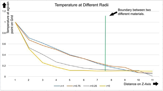
The normalized temperature and concentration distributions at various points in the capillary porous composite cylinder are depicted in Table 1 and Table 2 respectively. We can immediately see that, at each point in the capillary porous composite cylinder, the CPU and GPU computed results are similar. In addition, the value of temperature is highest and the value of concentration is lowest at the point on the capillary porous composite cylinder where the heat resource and mass resource are constantly applied. As we move away from this point, the values of the temperature decrease and concentration increase. At a point near the designated end of the capillary porous composite cylinder, the values of the temperature approach zero and concentration approach one.

Table 1. Comparison of GPU and CPU results for Capillary Porous Composite Cylinder (Concentration).
Table 2. Comparison of GPU and CPU results for Capillary Porous Composite Cylinder (Temperature).
Figure 4(a) and Figure 4(b) show the temperature and concentration distribution in the capillary porous composite cylinder with 4 different radiuses.
Furthermore, we also evaluated the performance of the GPU (NVIDIA Quadro FX 4800) in terms of solving heat and mass transfer equations by comparing its execution time to that of the CPU (Intel Xeon E5520).
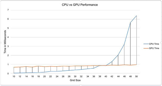
For the purpose of measuring the execution time, the same functions were implemented in both the device (GPU) and the host (CPU), to initialize the temperature and concentration and to compute the numerical solutions. In this case, we measured the processing time for different values of N. The graph in Figure 5 depicts the performance of the GPU versus the CPU in terms of the processing time.
 (a)
(a)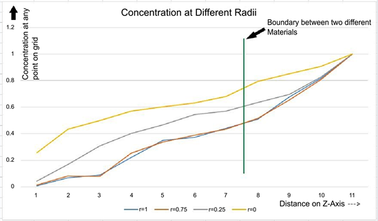 (b)
(b)
Figure 4. (a) Temperature distribution in the capillary porous composite cylinder; (b) Concentration distribution in the capillary porous composite cylinder.
We run the test for N running from 10 to 599 with increments of 30 and generally, the GPU performed the calculations a lot faster than the CPU.
1) When N was smaller than 16, the CPU performed the calculations faster than the GPU.
2) For N larger than 16 the GPU performance began to increase considerably.
Figure 5(a) and Figure 5(b) show some of our experimental results for both capillary porous composite cylinder.
Finally, the accuracy of our numerical solution was dependent on the number of iterations we performed in calculating each nodal point, where more iteration means more accurate results. In our experiment, we observed that after 9 or 10 iterations, the solution to the heat and mass equation at a given point became stable. For optimal performance, and to keep the number of iterations the same for both CPU and GPU, we used 10 iterations and experimental results for
 (a)
(a)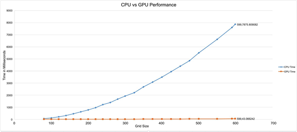 (b)
(b)
Figure 5. (a) Performance of GPU and CPU Implementations for capillary porous composite cylinder; (b) Performance of GPU and CPU Implementations for capillary porous composite cylinder with incremental number of nodes.
capillary porous composite cylinder show about 7 times speed-up.
6. Conclusions and Future Work
We have presented our numerical approximations to the solution of the heat and mass transfer equation with the second kind of boundary and given initial conditions for capillary porous composite cylinder using finite difference method on GPGPUs. Our conclusion shows that finite difference method is well suited for parallel programming. We implemented numerical solutions utilizing highly parallel computations capability of GPGPU on nVidia CUDA. In [19] and [20] we have demonstrated that GPU can perform significantly faster than CPU in the field of numerical solution to heat and mass transfer. Experimental results for capillary porous composite cylinder indicate that our GPU-based implementation shows a significant performance improvement over CPU-based implementation and the maximum observed speedups are about 7 times.
There are several avenues for future work. We would like to test our algorithm on different GPUs and explore the new performance opportunities offered by newer generations of GPUs. It would also be interesting to explore more tests with large-scale data set. Finally, further attempts will be made to explore more complicated problems both in terms of boundary and initial conditions as well as other geometries. An additional interesting study will be studying the cases of radially composite cylinders under different environmental conditions.
Conflicts of Interest
The authors declare no conflicts of interest regarding the publication of this paper.
Cite this paper
Narang, H., Wu, F. and Mohammed, A.R. (2018) An Efficient Acceleration of Solving Heat and Mass Transfer Equations with the Second Kind Boundary Conditions in Capillary Porous Composite Cylinder Using Programmable Graphics Hardware. Journal of Computer and Communications, 6, 24-38. https://doi.org/10.4236/jcc.2018.69003
References
- 1. Owens, J.D., Luebke, D., Govindaraju, N., Harris, M., Krger, J., Lefohn, A.E. and Purcell, T.J. (2007) A Survey of General-Purpose Computation on Graphics Hardware. Computer Graphics Forum, 26, 80-113. https://doi.org/10.1111/j.1467-8659.2007.01012.x
- 2. NVIDIA Corporation (2009) NVIDIA Programming Guide 2.3. https://www.nvidia.com/zh-cn/
- 3. Luikov, A.V. (1966) Heat and Mass Transfer in Capillary Porous Bodies. Pergamon Press, Oxford. https://doi.org/10.1016/B978-1-4832-0065-1.50010-6
- 4. Narang, H. and Nekkanti, R. (2001) Wavelet-Based Solution to Time-Dependent Two-Point Initial Boundary Value Problems with Non-Periodic Boundary Conditions. Proceedings of the IATED International Conference Signal Processing, Pattern Recognition & Applications, Rhodes, Greece, 3-6 July 2001.
- 5. Narang, H. and Nekkanti, R. (2002) Wavelet-Based Solution of Boundary Value Problems Involving Hyperbolic Equations. Proceedings from the IATED International Conference Signal Processing, Pattern Recognition & Applications, Grete, Greece, 25-26 June 2002, 470-473.
- 6. Narang, H. and Nekkanti, R. (2001) Wavelet-Based Solutions to Problems Involving Parabolic Equations. Proceedings of the IATED International Conference Signal Processing, Pattern Recognition & Applications, Rhodes, Greece, 3-6 July 2001.
- 7. Narang, H. and Nekkanti, R. (2002) Wavelet-Based Solution to Elliptic Two-Point Boundary Value Problems with Non-Periodic Boundary Conditions. Proceedings from the WSEAS International Conference in Signal, Speech, and Image Processing, Skiathos, Skiathos Island, Greece, 25-28 September 2002.
- 8. Narang, H. and Nekkanti, R. (2003) Wavelet-Based Solution to Some Time-Dependent Two-Point Initial Boundary Value Problems with Non-Linear Non-Periodic Boundary Conditions. International Conference on Scientific Computation and Differential Equations, SCICADE 2003, Trondheim, Norway, 30 June-4 July 2003.
- 9. Narang, H. and Nekkanti, R. (2004) Wavelet Based Solution to Time-Dependent Two Point Initial Boundary Value Problems with Non-Periodic Boundary Conditions Involving High Intensity Heat and Mass Transfer in Capillary Porous Bodies. IATED International Conference Proceedings, Rhodes, Greece, 30 June-2 July 2003, 130-135.
- 10. Ambethkar, V. (2008) Numerical Solutions of Heat and Mass Transfer Effects of an Unsteady MHD Free Conective Flow Past an Iffinite Vertical Plate With Constant Suction. Journal of Naval Architecture and Marine Engineering, 5, 27-36.
- 11. Krüger, J. and Westermann, R. (2003) Linear Algebra Operators for GPU Implementation of Numerical Algorithms. ACM Transactions on Graphics (Proceedings of SIGGRAPH), San Diego, California, 27-31 July 2003, 908-916.
- 12. Bolz, J., Farmer, I., Grinspun E. and Schrooder, P. (2003) Sparse Matrix Solvers on the GPU: Conjugate Gradients and Multigrid. ACM Transactions on Graphics (Proceedings of SIGGRAPH), San Diego, California, 27-31 July 2003, 917-924. https://doi.org/10.1145/1201775.882364
- 13. Goodnight, N., Woolley, C., Luebke, D. and Humphreys, G. (2003) A Multigrid Solver for Boundary Value Problems Using Programmable Graphics Hardware. Proceeding of Graphics Hardware, San Diego, California, 26-27 July 2003, 102-111.
- 14. Harris, M., Baxter, W., Scheuermann T. and Lastra, A. (2003) Simulation of Cloud Dynamics on Graphics Hardware. Proceedings of Graphics Hardware, San Diego, California, 26-27 July 2003, 92-101.
- 15. Harris, M.J. (2003) Real-Time Cloud Simulation and Rendering. PhD Thesis, The University of North Carolina, Chapel Hill.
- 16. Kim, T. and Lin, M. (2003) Visual Simulation of Ice Crystal Growth. Proceedings of SIGGRAPH/Eurographics Symposium on Computer Amination, San Diego, California, 26-27 July 2003, 86-97.
- 17. Lefohn, A., Kniss, J., Hansen, C. and Whitaker, R. (2003) Interactive Deformation and Visualization of Level Set Surfaces Using Graphics Hardware. IEEE Visualization, Seattle, WA, USA, 19-24 October 2003, 75-82. https://doi.org/10.1109/VISUAL.2003.1250357
- 18. GPGPU Website. http://www.gpgpu.org
- 19. Narang, H., Wu, F., Ogunniyan, A. and Mohammed, A.R. (2017) An Efficient Acceleration of Solving Heat and Mass Transfer Equations with Second Kind Boundary and Initial Conditions in Solid and Hollow Cylinder Using Programmable Graphics Hardware. Journal of Computations & Modelling, 7, 29-50.
- 20. Narang, H., Wu, F. and Mohammed, A.R. (2017) An Efficient Solution of Heat and Mass Transfer Equations Using Programmable General Purpose Processing Unit under Natural Boundary Conditions in Capillary Porous Solid and Hollow Cylinder. International Advanced Research Journal in Science, Engineering and Technology, 4, 1-11.