Journal of Computer and Communications
Vol.04 No.17(2016), Article ID:73136,8 pages
10.4236/jcc.2016.417003
Microcontroller-Based Sinusoidal Voltage Generation for Electrical Bio-Impedance Spectroscopy Applications
Juan A. Castro1, A. Olmo1,2, Pablo Pérez1,2, A. Yúfera1,2
1Departamento de Tecnología Electrónica, Universidad de Sevilla, Seville, Spain
2Instituto de Microelectrónica de Sevilla, CSIC, Sevilla, Spain
![]()
Copyright © 2016 by authors and Scientific Research Publishing Inc.
This work is licensed under the Creative Commons Attribution-NonCommercial International License (CC BY-NC 4.0).
http://creativecommons.org/licenses/by-nc/4.0/


Received: October 30, 2016; Accepted: December 26, 2016; Published: December 29, 2016
ABSTRACT
A sinusoidal voltage wave generator is proposed based on the use of micro-processor digital signals with programmable duty-cycles, with application to real-time Electrical Cell-substrate Impedance Spectroscopy (ECIS) assays in cell cultures. The working principle relies on the time convolution of the programmed microcontroller (µC) digital signals. The expected frequency is easily tuned on the bio-impedance spectroscopy range [100 Hz, 1 MHz] thanks to the µC clock frequency selection. This system has been simulated and tested on the 8 bits µC Arduino™ Uno with ATmega328 version. Results obtained prove that only three digital signals are required to fit the general specification in ECIS experiments, below 1% THD accuracy, and show the appropriateness of the system for the real-time monitoring of this type of biological experiments.
Keywords:
Sinusoidal Voltage Generator, Electrical Cell-Substrate Impedance Spectroscopy (ECIS), Bioimpedance, Microcontroller (µC), Total Harmonic Distortion (THD)

1. Introduction
Sinusoidal voltage generators are basic building blocks in many instrumentation and signal acquisition systems, as in spectroscopy analysis, where AC voltage signals must be generated in a defined frequency range [1] [2] [3] . The application to impedance measurements in cell-culture assays is actually known as Electrical Cell-substrate Impedance Spectroscopy (ECIS) technique [3] . Real- time signal generation is essential for the monitoring of many biological pro- cesses. The cell bio-impedance obtained can be directly related with several biological processes, such us motility, cell attachment, cell index, membrane transfer, tumor cells detection, etc., employing only one cell seeding, since all data are obtained from the same cell culture. This means the employment of a non-de- structive process that avoids endpoint-based protocols.
In ECIS, excitation is usually done with ac current sources, while processing steps are based on algorithms useful to decode the sample voltage response to signal excitation [4] . This paper describes how sinusoidal voltage signals required in ECIS setups can be derived from digital signals using a microcontroller (µC). As a difference to other recent µC based realizations for a fixed frequency [5] and to other current bioimpedance monitoring systems [4] [5] [6] [7] , our work uses the mathematical properties of time convolution and the adequate design of digital signals. This way, we are avoiding the synchronization with the input signals as a requirement for the technique to work well, therefore facilitating the implementation of the monitoring circuit and improving the robustness of its spectroscopy results.
2. Methodology
2.1. Sinusoidal Waveform Generation
The proposed approach is based on the design of digital signals in which the duty-cycle (δ) can be programmed. This fact is used for the high harmonics exact cancellation. Signal processing is performed in the frequency domain, whereas signal manipulation is done in the time domain. For a given digital signal fd(t), with period T, amplitude A and interval d at high state, the Cn Fourier coefficients at the harmonics ωn = nωo, are given by
 (1)
(1)
The sin(x) function has zeros when πnδ = mπ (n, m belong to N), being δ = d/T. A method to derive a sinusoidal voltage signal based on δ selection is proposed.
The mathematical basis of the proposed method is the time convolution of two signals. For two given functions, fd1(t) and fd2(t), the time convolution has a Fourier spectrum defined by the product of independent spectra of the functions Fd1(ω) and Fd2(ω) respectively, expressed as
 (2)
(2)
In particular, when the signals have a rectangular form with the same period, T, but different duty cycle δ, the frequency spectrum of each signal will have zero components at frequencies in which sin(πnδ) is cancelled. In this work, we assume that all digital outputs have the same amplitude. The basic block pro- cessing scheme (Figure 1) considers the FFT’s of M rectangular signals with the same period T, and different δn(n = 1, 2, ∙∙∙, M).
For fd1(t) rectangular signal, with δ = 0.5, all even Cn coefficients are cancelled. The spectrum of fd2(t) must be designed to null the first useless odd harmonic of fd1(t) that is 3ωo. By selecting its duty-cycle as one third of T, the first non-desired odd harmonic (3ωo) is cancelled since sin(πn/3) is zero when 3|n (C3, C6, ∙∙∙). It can be easily deduced that considering only two functions fd1(t) and fd2(t), with δ = 0.5 and δ = 0.33, all non-eliminated harmonics are co-primes with 2 and 3. This is shown more clearly in Figure 2. For this reason, the Fourier coefficients after multiplying these functions are given by

Figure 1. Proposed block diagram for sinusoidal voltage generation. Square signals are generated by the microcontroller and then convoluted.

Figure 2. Harmonic spectra of rectangular signals with 50% and 33% of duty-cycle (a, b) and Vn,2 signal (c). As it can be observed in Vn,2 signal, the harmonic cancellation is produced in even harmonic frequencies and in multiples of the third harmonic.
 (3)
(3)
where Vn,i represents the nth coefficient of the complex Fourier series for the convolution of the i signals, and Pi, the ith element of the ordered set composed by the prime numbers, P, i.e. P = {2, 3, 5, ∙∙∙}. In the case i = 2, Equation (4) is obtained. This process can be extended to three or more digital signals, increasing the lower element in P set, which means to increase the sinusoidal voltage signal quality.
 (4)
(4)
2.2. Experimental Setup
The proposed system has been tested on the 8 bits microcontroller (µC) Ar- duino™ Uno with ATmega328 version. Arduino™ is an open-source electronics prototyping platform [8] . Besides the µC, we use a DAC 0808 to create an analog version, and a first order RC Smoothing Active Filter (SAF). The cutoff frequency of the SAF is programmed to the nearest higher frequency as the wanted signal. This paper will show the output to 100 Hz, 1 kHz and 10 kHz signals, and the SAF cutoff frequencies are 200 Hz, 2 kHz and 20 kHz respectively.
3. Results
3.1. Theoretical Results
Matlab® R2014b simulations have been performed for several digital signals. Figure 3 shows the waveforms obtained for rectangular functions with 1, 2, 3 and 4 convoluted signals, with duty-cycles of 0.5, 0.33, 0.2 and 0.14 respectively. Waveforms are presented after Fourier coefficients have been multiplied in the frequency domain, and then, the inverse Fourier transform is calculated. To evaluate the quality of the sinusoidal signals obtained, the Total Harmonic Distortion (THD) is observed in Figure 4.
Taking only three convoluted signals it is possible to obtain a THD below 1% (about 0.5%), which is usually enough in ECIS technique. Total Harmonic distortion expected as a function of the number of convoluted signals is represented in Figure 4. To select the working frequency it must be set the µC clock signal, a difference to other µC based realizations [5] . It was considered the ARM Cortex-M7 µC as an example for further implementation.
3.2. Experimental Results
Real-time signal generated by the 8 bits microcontroller is presented in the following figures, in which channel 1 is a sinusoidal wave produced by the Press 2 MHz Function Generator GF-232, and channel 2 shows the proposed generator output. In Figure 5, we can see that the approximate generator GF-232 THD is

Figure 3. Waveforms obtained for functions v1(t), v2(t), v3(t) and v4(t), the inverse FFT of Vn,1, Vn,2, Vn,3 and Vn,4 signals in Equation (3).
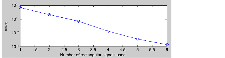
Figure 4. THD versus number of squared signals.
0.88%, while the proposed generator is 0.85%, being these two results approximately 0.3% higher than the theoretical THD expected result, around 0.5%, shown in section 3.1.
In Figure 6, the outputs of the four selected frequencies (100 Hz, 1 KHz, 10 KHz and 18.5 KHz) are presented. The highest frequency that can be achieved
![]()
Figure 5. Spectra of the 100 Hz sinusoidal signals of GF-232 (a) and the proposed generator output (b). We can observe the similarity of the two results, in spite of the low cost of our experimental implementation.
![]()
Figure 6. Comparatives between the commercial sine generator (blue) and the proposed generator (yellow) at 100 Hz (a), 1 KHz (b), 10 KHz (c) and 18.5 KHz (d). In (d), the high level language programming efects can be observed, increasing the rate of noise.
with the selected µC, with an acceptable rate of noise, is around 18.5 KHz. This is derived, mainly, by the clock drift and the high level programming language, which can be easily sorted out with another µC. With the proposed system, the frequency can be easily changed in real-time, what is of utmost importance in the monitorization of ECIS biological experiments.
4. Conclusion
This work presents an alternative sinusoidal voltage signal generator for real time Electrical Cell-substrate Impedance Spectroscopy assays employing cell cultures. The signal synthesis algorithm proposed relies on time convolution of rectangular signals, with a programmable duty-cycle easily defined by µC circuits. Furthermore, frequency can be configured in real time, enabling advanced spectroscopy applications. Results obtained from simulations prove that only three digital signals are required to fit the general specifications in ECIS experiments, below 1% THD, being confirmed these theoretical results with the proposed experimental work. The circuit solution proposed as programmable sinusoidal voltage signal generator is simple, robust and easy to be implemented for this and other spectroscopy applications.
Acknowledgements
This work was supported in part by the Spanish founded Project: TEC 2013- 46242-C3-1-P: Integrated Microsystem for Cell Culture Assays, co-financed with FEDER.
Cite this paper
Castro, J.A., Olmo, A., Pérez, P. and Yúfera, A. (2016) Microcontroller-Based Sinusoidal Voltage Generation for Electrical Bio-Impedance Spectro- scopy Applications. Journal of Computer and Communications, 4, 51-58. http://dx.doi.org/10.4236/jcc.2016.417003
References
- 1. Yúfera, A. and Rueda, A. (2010) Design of a CMOS Closed-Loop System with Applications to Bio-Impedance Measurements. Microelectronics Journal, 41, 231-239.
https://doi.org/10.1016/j.mejo.2010.02.006 - 2. Daza, P., Olmo, A., Canete, D. and Yúfera, A. (2013) Monitoring Living Cell Assays with Bio-Impedance Sensors. Sensors and Actuators B: Chemical, 176, 605-610.
https://doi.org/10.1016/j.snb.2012.09.083 - 3. Giaever, I. and Keese, Ch. (1986) Use of Electric Fields to Monitor the Dynamical Aspect of Cell Behaviour in Tissue Culture. IEEE Transactions on Biomedical Engineering, 33, 242-247.
https://doi.org/10.1109/TBME.1986.325896 - 4. Pérez-García, P., Maldonado, A., Yúfera, A., Huertas, G., Rueda, A. and Huertas, J.L. (2016) Towards Bio-Impedance Based Labs: A Review. Journal of Electrical Engineering, 4, 116-127.
- 5. Wissenwasser, H., Vellekoop, M.J. and Heer, R. (2011) Signal Generator for Wireless Impedance Monitoring of Microbiological Systems. IEEE Transactions on Instrumentation and Measurements, 60, 2039-2046.
- 6. Lee, W. and Cho, S.H. (2015) Integrated All Electrical Pulse Wave Velocity and Respiration Sensors Using Bio-Impedance. IEEE Journal of Solid-State Circuits, 50, 776-785.
https://doi.org/10.1109/JSSC.2014.2380781 - 7. Pradhan, R., Mandal, M., Mitra, A. and Das, S. (2014) Assessing Cytotoxic Effect of ZD6474 on MDA-MB-468 Cells Using Cell-Based Sensor. IEEE Sensors Journal, 14, 1476-1481.
https://doi.org/10.1109/JSEN.2013.2296717 - 8. AA.VV. Arduino Uno (2016).
https://www.arduino.cc/en/Main/ArduinoBoardUno