Journal of Materials Science and Chemical Engineering
Vol.1 No.6(2013), Article ID:39490,4 pages DOI:10.4236/msce.2013.16003
Pt Deposition on Anode Enhances the Performance of Dye-Sensitized Solar Cell with Non-Cross-Linked Gel Electrolyte
1Department of Electrical and Computer Engineering, Akashi College of Technology, Akashi, Japan
2Akashi College of Technology, Akashi, Japan
Email: ohmukai@akashi.ac.jp
Copyright © 2013 Masato Ohmukai, Jun Kyokane. This is an open access article distributed under the Creative Commons Attribution License, which permits unrestricted use, distribution, and reproduction in any medium, provided the original work is properly cited.
Received September 4, 2013; revised October 4, 2013; accepted October 11, 2013
Keywords: Ruthenium Ion Complex; Dye-Sensitized Solar Cell; Non-Cross-Linked Fluorinated Gel Electrolyte; Pt Layer; DC Sputtering Deposition
ABSTRACT
We fabricated dye-sensitized solar cells with non-cross-linked fluorinated gel electrolyte. The application of fluorinated gel to electrolyte is a challenging issue at present. The gelation of the electrolyte is of importance in order to solve the problem in the durability of the cell. We investigated, in this article, the effect of Pt deposition on the anode of the cell. The Pt was deposited by means of a DC sputtering technique. The studies showed that the deposition time strongly affected both open voltage and short-circuit current of the cell. The adaptive thickness of the Pt layer was determined to be 10 nm for the non-cross-linked fluorinated gel electrolyte cells.
1. Introduction
Dye-sensitized solar cells have attracted much attention these twenty years, since this new type of solar cells without any pn junctions was reported [1,2] in 1991 for the first time. The vast amount of efforts has been devoted to the improvement of its performance [3,4]. The conversion efficiency has reached ten percents [5] and so the application is now expected strongly. In order to replace this kind of solar cells with the silicon ones, the efficiency requires the same level of silicon solar cells at least. Recently large size of cells was fabricated with maintaining conversion efficiency [6].
The other big problem of the dye-sensitized solar cells is its poor durability. Since the cell includes electrolyte as one side of the electrodes, the leakage of the electrolyte inevitably limits its durability. As a preferable idea to prevent the electrolyte leakage, gelation of the electrolyte has been proposed [7,8]. Some researchers have been challenging with cross-linking of a polymer [9]. We have been engaged on the other hand in the application of non-cross-linked fluorinated gel electrolytes that have already been proposed to apply to a secondary battery [10]. The non-cross-linked fluorinated gel electrolyte does not require any bridging process of chemical reaction such as ultraviolet irradiation, having an advantage of a simple and low-cost gelation procedure from the viewpoint of manufacturing.
The cell consists of two transparent electrodes, between which the gel electrolyte is put, where one of the electrode was covered with the aggregate of TiO2 nanoparticles adsorbing dye. The aggregated nanoparticle TiO2 layer—often addressed nanoporous TiO2—is one of the critical part of the solar cell [5,11]. Nowadays, TiO2 coated stainless grid has been challenged for the purpose of low cost [12-14]. On the other hand, the counter electrode has not been well studied yet. The most simply way to form the cell, only FTO substrate is used as a counter electrode. Some researchers have studied coating effect of the FTO counter electrode. For example, Pt films sputtered on FTO improved the cell performance till the sputtering time was 90 s at most [15]. It has been reported that a kind of polymer over Pt enhanced the performance to 2.84% [16]. There is another report that carbon was better than Pt and that surface roughness affected open voltage noticeably [17]. Very recently, graphite and pencil-lead was applied on FTO counter electrodes [18]. The interesting results have been reported that carbon and platinized Sb-doped SnO2 powder was sprayed on ITO [19].
We fabricated the cells with a variation of sputtering time of Pt deposited on FTO counter electrodes; ranging between 1 and 6 min, which corresponds to 5 and 30 nm, respectively. We then studied the influence on the performance of the cells from the point of view of I-V characteristics.
2. Experimental Details
We mixed 1 g of slurry (P4TH055 offered by Sumitomo Titanium) including 30 wt% of TiO2 with polyethylene glycol (PEG), the amount of which was 10 wt% of the slurry, to make paste with the help of the addition of Triton X (a nonionic surfactant of 15 μl) to increase viscosity. The size of TiO2 particles in the slurry is not claimed clearly, but ranging between 50 - 70 nm. Further P-25 of titania nano particles (20 nm) were added to enhance the cell performance. The amount of added P-25 was the same weight as the TiO2 in the slurry. The paste was spread on a fluorine doped tin oxide (FTO) substrate at the thickness of 58 μm. This was then annealed at 450˚C [13] for 30 minutes to remove binders and solvent to be a cathode. The TiO2 deposited substrate was soaked in a solution of ruthenium complex dye (Ru(4,4’-dicarboxy- 2,2’bipyridine)2(NCS)2) in ethanol (1 × 10⁴ mol/l) at 50˚C for 2 hours to adsorb the dye.
The counter electrode (anode) of an FTO substrate was sputtered with a Pt target using a portable sputtering apparatus of VPS-020 by ULVAC. The sputtering time was varied between 1 and 6 minutes. The thickness of Pt was confirmed by means of an interference microscope.
We describe here the preparation of gel electrolyte. Dimethyl sulfoxide was mixed with LiI (10 mmol/g) for 20 minutes with the help of ultrasonic agitation. We then added 2-acrylamid-2-methyl-propanesulfonic acid (AMPS) to this solution and mixed for 200 minutes further. The AMPS is one of fluorinated oligomers [10]. The amount of AMPS added for gelation should be roughly larger than 330 g/l; the critical gelation density that was obtained experimentally. If the density of the AMPS is too low, spontaneous cohesion is possibly hard to occur owing to a large distance between each oligomer. We finally formed a solar cell by putting the gel electrolyte between a cathode and anode and sealed the environs of the cell with epoxy resin.
We investigated the I-V characteristics of the solar cells by measuring the current and voltage appeared at the cell when a variable resistive load was connected to the cell that was irradiated by white light (AM 1.5) from a Xenon lamp (UXL500SX by Ushio) at the intensity of 55 mW/cm2. The resistive load was varied between 0 and 100 kΩ.
3. Results and Discussion
We show the I-V characteristics in Figure 1 obtained from the solar cell exposed in the white light. The thickness of Pt determined with an interference microscope was 5, 7, 9, 18 and 30 nm, which corresponds to the sputtering time of 1 to 6 minutes. The results show that the sputtering time of 3 minutes provided the maximum open voltage of 0.52 V and the maximum short-circuit current of 2.33 mA at the same time. The maximum generating power is shown in Figure 2 as a function of sputtering time. It is apparent that when the sputtering time was 3 minutes. The maximum generating power was noticeably as large as 0.56 mW. The FF value of this cell was 0.46 that is less than 0.48 of the cell with the sputtering time of 1 minute.
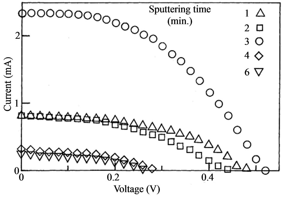
Figure 1. The I-V characteristics of the cell exposed in the white light. The parameter of the sputtering time was varied between 1 and 5 minutes.
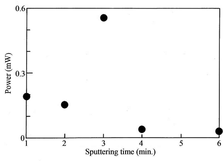
Figure 2. The maximum output power of the cell as a function of the sputtering time. The power is maximum at the sputtering time of 3 minutes.
The experimental results described above are quite simple but have deep meanings. The Pt deposition enhances the cell performance but excess deposition suppresses it contrarily. It implies that slight Pt deposition is favorable but does not indicate that Pt electrode is not appropriate. With the longer sputtering time, it possibly provides the smooth Pt thin layer. We speculate that the speckled state of Pt seems to be critical for the high performance of the cell. The Pt state deposited on the FTO substrate is the next interesting point.
We consider the open voltage here. The photo voltage has been studied in relation to carrier injection at the cathode mainly [20-22]. The open voltage is dependent on temperature in the manner of 2.5 mV decrease with a degree increase in temperature. The fact suggests the shift of the TiO2 conduction band edge potential [21]. On the other hand, the variation of the open voltage is quite large in Figure 1. The open voltage of the cell with the sputtering time of 3 minutes was 0.52 V, which is twice as large as that of the cell with the 6 minutes sputtered cathode. This indicates the interface state between the cathode and the electrolyte is of importance to obtain a high open voltage. Based on the tendency to have a maximum at 3 minutes, it does not simply mean that the electrolyte-Pt contact is required. The large open voltage derived from the rough surface with unevenness of the anode. When the sputtering time becomes larger than 4 minutes, the Pt deposited surface becomes smooth again and then the open voltage decreased in accordance with it.
A large dependence was also observed in the shortcircuit current in Figure 1. The biggest short-circuit current was 2.33 mA, which was also observed in the case of the sputtering time of 3 minutes. The value is 9.3 times as large as that in the 6 minutes sputtered sample. The short-circuit current is strongly dependent on the sputtering time of Pt deposition on the anode. T Asano et al. have reported the short-circuit current depended on the sort of electrolyte noticeably [23]. They concluded that the larger diffusivity coefficient of the Iodine ions enhances the short-circuit current of the cell. Our experimental results shows, on the other hand, that the interface state between the electrolyte and anode strongly affects the short-circuit current. This means that the characterization of the anode is no less important than the cathode that includes TiO2 and light absorbing dyes. The speckled form of the Pt surface possibly enhances the electric field at the surface to make the electron injection in the electrolyte easy. The roughened surface may be favorable for the anode.
4. Conclusion
A dye sensitized solar cell with non-cross-linked fluorinated gel electrolyte was fabricated and then the effect of the Pt deposition on the anode was investigated. Pt layers were deposited by means of a DC sputtering method. The experimental results show that there is the optimized sputtering time, which corresponds to the Pt layer thickness of 9 nm. At the optimized condition, the open voltage, short-circuit current and generating power became the largest at the same time. The fact tells us that the anode circumstance is no less important than the TiO2 and dye state where the electric power is generated. We infer that surface roughness of the Pt layer is critical for the high performance of the solar cell.
REFERENCES
- B. O’Regan and M. Grätzel, “A Low-Cost, High-Efficiency Solar Cell Based on Dye-Sensitized Colloidal TiO2 Films,” Nature, Vol. 353, No. 6346, 1991, pp. 737- 740. http://dx.doi.org/10.1038/353737a0
- M. K. Nazeeruddin, A. Kay, I. Rodicio, R. HumphryBaker, E. Mueller, P. Liska, N. Vlachopoulos and M. Grätzel, “Conversion of Light to Electricity by Cis-X2bis (2,2’-bipyridyl-4,4’-dicarboxylate)ruthenium(II) ChargeTransfer Sensitizers (X = Cl-, Br-, I-, CN-, and SCN-) on Nanocrystalline Titanium Dioxide Electrodes,” Journal of the American Chemical Society, Vol. 115, No. 14, 1993, pp. 6382-6390. http://dx.doi.org/10.1021/ja00067a063
- B. Li, L. Wang, B. Kang, P. Wang and Y. Qiu, “Review of Recent Progress in Solid-Satate Dye-Sensitized Solar Cells,” Solar Energy Materials and Solar Cells, Vol. 90, No. 5, 2006, pp. 549-573. http://dx.doi.org/10.1016/j.solmat.2005.04.039
- M. Grätzel, “Recent Advances in Sensitized Mesoscopic Solar Cells,” Accounts of Chemical Research, Vol. 42, No. 11, 2009, pp. 1788-1798. http://dx.doi.org/10.1021/ar900141y
- Y .Chiba, A. Islam, Y. Watanabe, R. Komiya, N. Koide and L. Han, “Dye-Sensitized Solar Cells with Conversion Efficiency of 11.1%,” Japanese Journal of Applied Physics, Vol. 45, No. 25, 2006, pp. L638-L640. http://dx.doi.org/10.1143/JJAP.45.L638
- W. J. Lee, E. Ramasamy, D. Y. Lee and J. S. Song, “DyeSensitized Solar Cells: Scale up and Current-Voltage Characterization,” Solar Energy Materials and Solar Cells, Vol. 91, No. 18, 2007, pp. 1617-1680. http://dx.doi.org/10.1016/j.solmat.2007.05.022
- Y. H. Lai, C. Y. Lin, J. G. Chen, C. C. Wang, K. C. Huang, K. Y. Liu, K. F. Lin, J. J. Lin and K. C. Ho, “Enhancing the Performance of Dye-Sensitized Solar Cells by Incorporating Nanomica Platelets in Gel Electrolyte,” Solar Energy Materials and Solar Cells, Vol. 94, No. 4, 2010, pp. 668-674. http://dx.doi.org/10.1016/j.solmat.2009.11.027
- S. Murai, S. Mikoshiba and S. Hayase, “Influence of Alkyl Dihalide Gelators on Solidification of Dye-Sensitized Solar Cells,” Solar Energy Materials and Solar Cells, Vol. 91, No. 18, 2007, pp. 1707-1712. http://dx.doi.org/10.1016/j.solmat.2006.12.018
- T. C. Wei, C. C. Wan and Y. Y. Wang, “Preparation and Characterization of a Micro-Porous Polymer Electrolyte with Cross-Linking Network Structure for Dye-Sensitized Solar Cell,” Solar Energy Materials and Solar Cells, Vol. 91, No. 20, 2007, pp. 1892-1897. http://dx.doi.org/10.1016/j.solmat.2007.07.005
- J. Kyokane, K. Shima and H. Sawada, “Electrical Properties of Fluorinated Gel Electrolytes Using High Ionic Conducting Solution and Its Application to Secondary Battery,” Thin Solid Films, Vol. 438/439, 2003, pp. 257- 261. http://dx.doi.org/10.1016/S0040-6090(03)00794-6
- X. Wu, L. Wang and Y. Qiu, “In Situ Synthesis of Mesoporous TiO2 Anatase Films and Their Photovoltaic Performance in Dye Sensitized Solar Cells,” Japanese Journal of Applied Physics, Vol. 45, 2006, pp. L1149-L1151. http://dx.doi.org/10.1143/JJAP.45.L1149
- H. Matsui, K. Okada, T. Kitamura and N. Tanabe, “Thermal Stability of Dye-Sensitized Solar Cells with Current Collecting Grid,” Solar Energy Materials and Solar Cells, Vol. 93, No. 6-7, 2009, pp. 1110-1115. http://dx.doi.org/10.1016/j.solmat.2009.01.008
- Y. Yoshida, Y. Noma, Y. Kashiwa, S. Kojima, T. Katoh and S. Hayase, “I2-Resistant TiOx/Ag Collector Fabricated by Arc Plasma Deposition for Dye-Sensitized Solar Cells,” Japanese Journal of Applied Physics, Vol. 47, No. 8, 2008, pp. 6484-6487. http://dx.doi.org/10.1143/JJAP.47.6484
- Y. Yoshida, S. S. Pandey, K. Uzaki, S. Hayase, M. Kono and Y. Yamaguchi, “Transparent Conductive Oxide LayerLess Dye-Sensitized Solar Cells Consisting of Floating Electrode with Gradient TiOx Blocking Layer,” Applied Physics Letters, Vol. 94, No. 9, 2009, Article ID: 093301. http://dx.doi.org/10.1063/1.3089845
- K. Onoda, S. Ngamsinlapasathian, T. Fujieda and S. Yoshikawa, “The Superiority of Ti Plate as the Substrate of Dye-Sensitized Solar Cells,” Solar Energy Materials and Solar Cells, Vol. 91, No. 13, 2007, pp. 1176-1181. http://dx.doi.org/10.1016/j.solmat.2006.12.017
- T. C. Wei, C. C. Wan and Y. Y. Wang, “Popy(n-vinyl-2- pyrrolidone)-Capped Platinum Nanoclusters on IndiumTin Oxide Glass as Counterelectrode for Dye-Sensitized Solar Cells,” Applied Physics Letters, Vol. 88, No. 10, 2006, Article ID: 103122. http://dx.doi.org/10.1063/1.2186069
- K. Imoto, K. Takahashi, T. Yamaguchi, T. Komura, J. Nakamura and K. Murata, “High-Performance Carbon Counter Electrode for Dye-Sensitized Solar Cells,” Solar Energy Materials and Solar Cells, Vol. 79, No. 4, 2003, pp. 459-469. http://dx.doi.org/10.1016/S0927-0248(03)00021-7
- Y. S. Wei, Q. Q. Jin and T. Z. Ren, “Expanded Graphite/ Pensil-Lead as Counter Electrode for Dye-Sensitized Solar Cells,” Solid-State Electronics, Vol. 63, No. 1, 2011, pp. 76-82. http://dx.doi.org/10.1016/j.sse.2011.05.019
- J. Halme, M. Toivola, A. Tolvanen and P. Lund, “Charge Transfer Resistance of Spray Deposited and Compressed Counter Electrodes for Dye-Sensitized Nanoparticle Solar Cells on Plastic Substrates,” Solar Energy Materials and Solar Cells, Vol. 90, No. 7-8, 2006, pp. 872-886. http://dx.doi.org/10.1016/j.solmat.2005.05.007
- H. Kusama and H. Sugihara, “Density Functional Study of Alkylpyridine-Iodine Interaction and Its Implications in the Open-Circuit Photovltage of Dye-Sensitized Solar Cell,” Solar Energy Materials and Solar Cells, Vol. 90, No. 7-8, 2006, pp. 953-966. http://dx.doi.org/10.1016/j.solmat.2005.05.014
- A. Usami, S. Seki, Y. Mita, H. Kobayashi, H. Miyashiro and N. Terada, “Temperature Dependence OF Open-Circuit Voltage in Dye-Sensitized Solar Cells,” Solar Energy Materials and Solar Cells, Vol. 93, No. 6-7, 2009, pp. 840-842. http://dx.doi.org/10.1016/j.solmat.2005.05.014
- B. Mahrov, G. Boschloo, A. Hagfeldt, L. Dloczik and T. Dittrich, “Photovoltage Study of Charge Injection from Dye Molecules into Transparent Hole and Electron Conductors,” Applied Physics Letters, Vol. 84, No. 26, 2004, pp. 5455-5457.
- T. Asano, T. Kubo and Y. Nishikitani, “Short-Circuit Current Density Behavior of Dye-Sensitized Solar Cells,” Japanese Journal of Applied Physics, Vol. 44, No. 9A, 2005, pp. 6776-6780. http://dx.doi.org/10.1143/JJAP.44.6776