Open Journal of Acoustics
Vol.3 No.3A(2013), Article ID:36860,3 pages DOI:10.4236/oja.2013.33A003
Increase Activity Cavitations in Liquids and Melts at Ultrasonics Processing
Department of Electronic Technique and Technology, University of Informatics and Radioelectronics, Minsk, Belarus
Email: vlanin@bsuir.by
Copyright © 2013 Vladimir L. Lanin. This is an open access article distributed under the Creative Commons Attribution License, which permits unrestricted use, distribution, and reproduction in any medium, provided the original work is properly cited.
Received July 5, 2013; revised August 5, 2013; accepted August 12, 2013
Keywords: Ultrasonic; Cavitation; Gas Cavities; Liquids; Melts
ABSTRACT
Increase of efficiency of cavitation processes in liquids and melts is reached by gas cavities saturation with the sizes not exceeding the resonant sizes of cavitation germs. Gas saturation of liquids and melts raises level of cavitation pressure upon 20% - 25% that intensifies US processing: cleaning, soldering and metallization.
1. Introduction
At ultrasonic (US) processing in liquids and melts: pollution removal, metallization of nonmetallic materials, disperse microand nano-dimensional powder materials, it is important to form cavitation area with adjustable erosive activity. However, US fields in baths with various quantities of radiators are characterized by non-uniformity of distribution US pressure and distinctions in intensity cavitation areas [1].
In liquids the quantity of cavitation, germs does not give in to the exact account as depends on many factors: gas maintenances in a liquid, quantities of firm particles, ambient temperatures, external pressure, etc. Not all cavitation germs participate in cavitation process, but only those from them which under action US pressure have reached the critical sizes. The cavitation threshold decreases, if the liquid environment influences an ionizing radiation or an electric current. Both these influences are connected with formation of new cavitation germs in the liquids. However, by these methods of activation, cavitation process remains non-stationary and difficultly operated [2].
Perspective direction in increase of cavitation processes efficiency is gas saturation of a liquid by cavities [3,4], with the sizes not exceeding the resonant sizes of germs, i.e. (10 - 50) ×10−6 m. Increase in the sizes of cavities will lead their premature collapse, and very small sizes complicate cavitation growth of cavities in US field [5].
2. Experimental
For estimation intensity, cavitation processes in liquids use the index of a cavitation defined by the relation of total volume of cavities ΣVк to volume of a liquid V [6]:
 (1)
(1)
The total volume cavities ΣVк is equal:
 , (2)
, (2)
where N—number cavities, Rmax—radius of cavities in a stage of the greatest expansion.
Experimental data testify, that cavitation area is, as a rule, in a near zone US radiator, therefore US activated liquids volume it is possible to present as product of the area of radiator Sr on height of cavitation area h. Taking into account these assumptions, Expression (1) will assume the following kind:
 (3)
(3)
Using the equation of ideal gas condition receive:
 (4)
(4)
where p—gas pressure, V—gas volume, mм—weight of gas molecules, R—gas constant, Т—gas temperature.
Regulating pressure and speed of gas distribution it is possible to operate number of the gas molecules N entered into a near zone of US radiator as potential cavitation germs.
At gas activation to a liquid from the compressor with the help of nozzle submitted air or inert gas argon with pressure to 0.1 - 0.2 МPа. For uniformity of the size of gas cavities in a liquid on exit of nozzle is established the filter-membrane with cells which were formed by laser radiation with high accuracy and repeatability of the sizes. The nozzle (Figure 1) consists of the union 1, the case of 2 and two porous filters received by powder metallurgy from oxide titan. The filter 3 has the sizes of apertures 2 - 5 microns, the filter 5 - 100 - 200 microns.
For creation of cavities of the micron sizes 4 it is necessary to satisfy following conditions: pressure of air should not exceed 0.2 - 0.3 МPа, and the distance between apertures in the filter in comparison with diameter of cavities should be considerable. These conditions in certain degree prevent association of cavities of the micron sizes in the big gas cavities.
At gas activation of a melt submitted on the converter 1 electric fluctuation by frequency 20 - 44 kHz and amplitude 50 - 75 mkm from US generator. In a solder melt immersed US radiator 2 so that a backlash between it and a soldered element 5 made 0.25 - 1.5 mm. Through a tube 3 and a capillary-porous body 4 in a direction to a soldered surface in a melt of solder 6 entered inert gas— argon (Figure 2). The sizes of capillaries in a porous body are chosen such that the sizes of formed gas cavities did not exceed the resonant sizes of cavitation germs of in a melt of Sn-Pb solder, i.e. 10 - 50 microns [7].
The greatest spectral density of a cavitation noise is in the frequency band from 20-th up to 40-th harmonics of the base frequency of the ultrasonic converter as 22 kHz at acoustic pressure 2 × 10⁵ Pa. It is offered to measure the square of a noise level over the range of the greatest spectral density of a cavitation noise and depending on their value to judge about the value of cavitation pressure in liquid surroundings [8].
The scheme of a cavitometr (Figure 3) consists of a piezoelectric sensor, an active filter creating a shear sternness of frequency characteristic curve less than 24 dB an octave, a square-law detector, and a recording device. The indications of this device have linear dependence on active power in range of 0 - 2 kW. The cavitometr measures cavitation pressure from 5 up to 5 × 10⁴ Pa in the frequency band 18 - 60 kHz with accuracy ±10%.
The pressure in cavitation area is perceived by a measuring probe 1, attached to a piezoelectric transducer 3 with the elastic waveguide 2. The electrical signal from
Figure 1. Nozzle for gas activation in liquids.
the transducer 3 comes to the amplifier 4, arranged in a body of the sensor and serving for coordinating a highohms circuit of the transducer with the input of the measuring device. The attenuator 5 serves for attenuation of input signal. The band-pass filter 6, made on the Chebushev scheme of the third order with band of 100 - 200 kHz, selects a portion of the spectrum of a signal, characteristic for cavitation impulses. After the amplification, the signal passes through circuits of the mean-square detector 8 and the amplifier 9 and then moves to indicator. Unit 10 is a power supply of the measuring device and sensor.
To the analysis of thermal fields it is applied mobile thermal camera MobIRМ4 with a sensitive element - microbolometer UFPA (160 × 120 pixels, 35 mm), 8 - 14 microns working in a spectral range. The size of a field of the analysis has made 25˚ × 19˚, focus of 12.6 mm. Sensitivity of the thermal camera 0.1˚С.
Measurements were spent on distance of 50 sm from a liquid upper edge. Device adjustment has been made on a reference source of boiling water. For stability of results, the measurements were spent in the form of several series after bath warming up in a current of 20 minutes, and then by means of program IR Analyzer V1.7 the thermal fields of distribution of temperatures in the set sites of a bath is received.
3. Results and Discussions
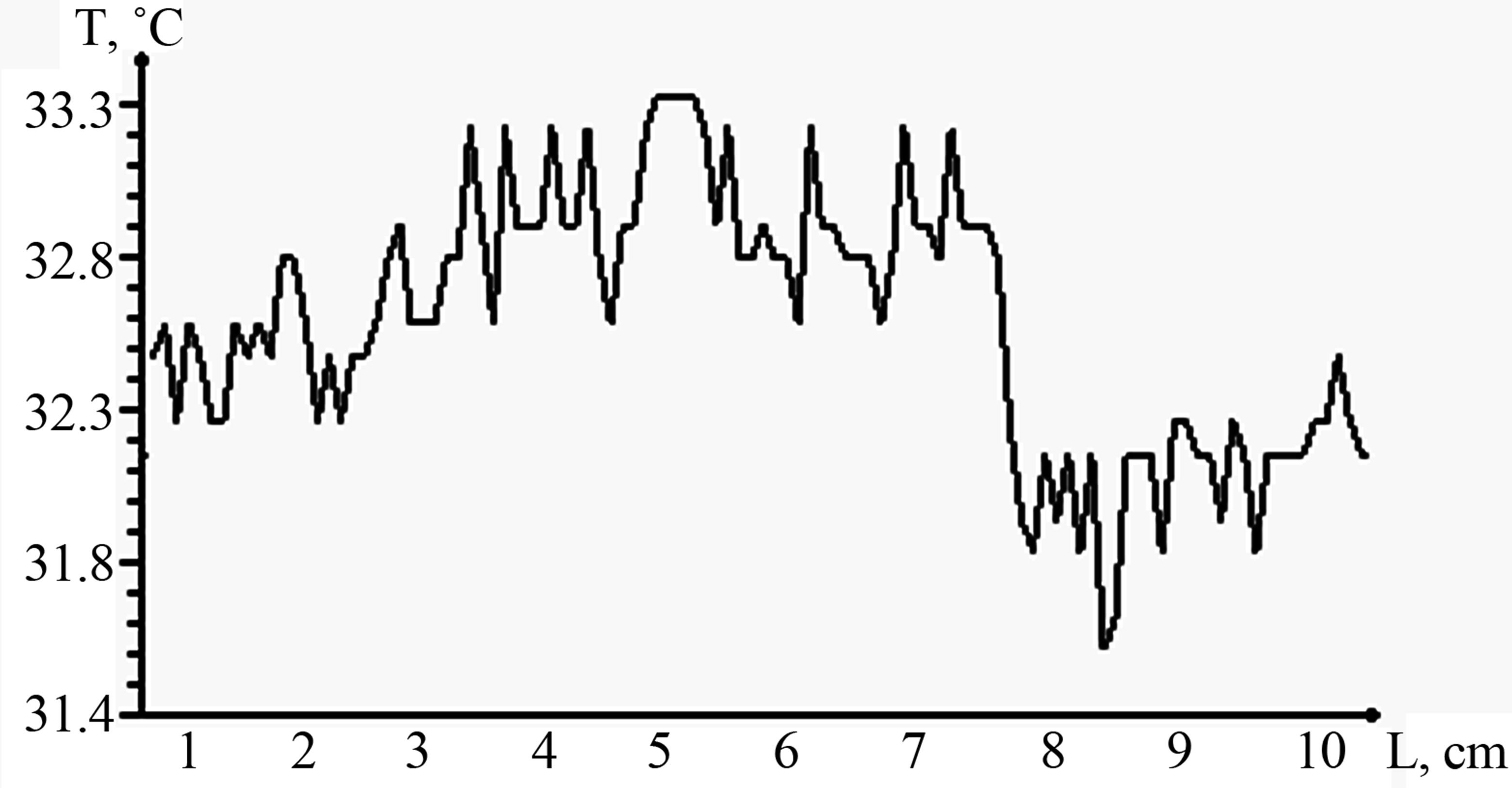
The analysis of thermal fields has shown that the liquid temperature in US bath as a result of cavitation process raises. The greatest increase (to 10˚C) occurs in a zone of the developed cavitation that is connected with warmth allocation at a collapse of cavitation cavities (Figure 4). At gas activation temperature of the liquids near to a nozzle approximately on 0.7˚C above in comparison with temperature on some distance from it.
Gas saturation of liquids and melts causes increase in cavitation pressure depending on speed of gas and sizes of filter cells. Under the influence of elastic US fluctuations, the formed cavitations germs pulse in a melt near to a surface of a soldered surface and slam at US pressure 2·105 Pa, created on a compression half-cycle. Pressure at which inert gas moved in a melt, depended on viscosity of solder and amplitude US fluctuations.
By help of cavitation indicator it is established that gas cavities with the sizes 10 - 50 microns slammed, increasing level of cavitation pressure that activates US processing, including metallization by fusible solders of nonmetallic materials.
Local cavitation pressure in a melt at the expense of initiation of a considerable quantity of cavitation germs increased on 20% - 25%, and reached a maximum at speed of inert gas of 4 - 6 m/min and the sizes of cells 10 microns (Figure 5). The big sizes of cavities (over 100 microns) result to formation of a gas cavity which does
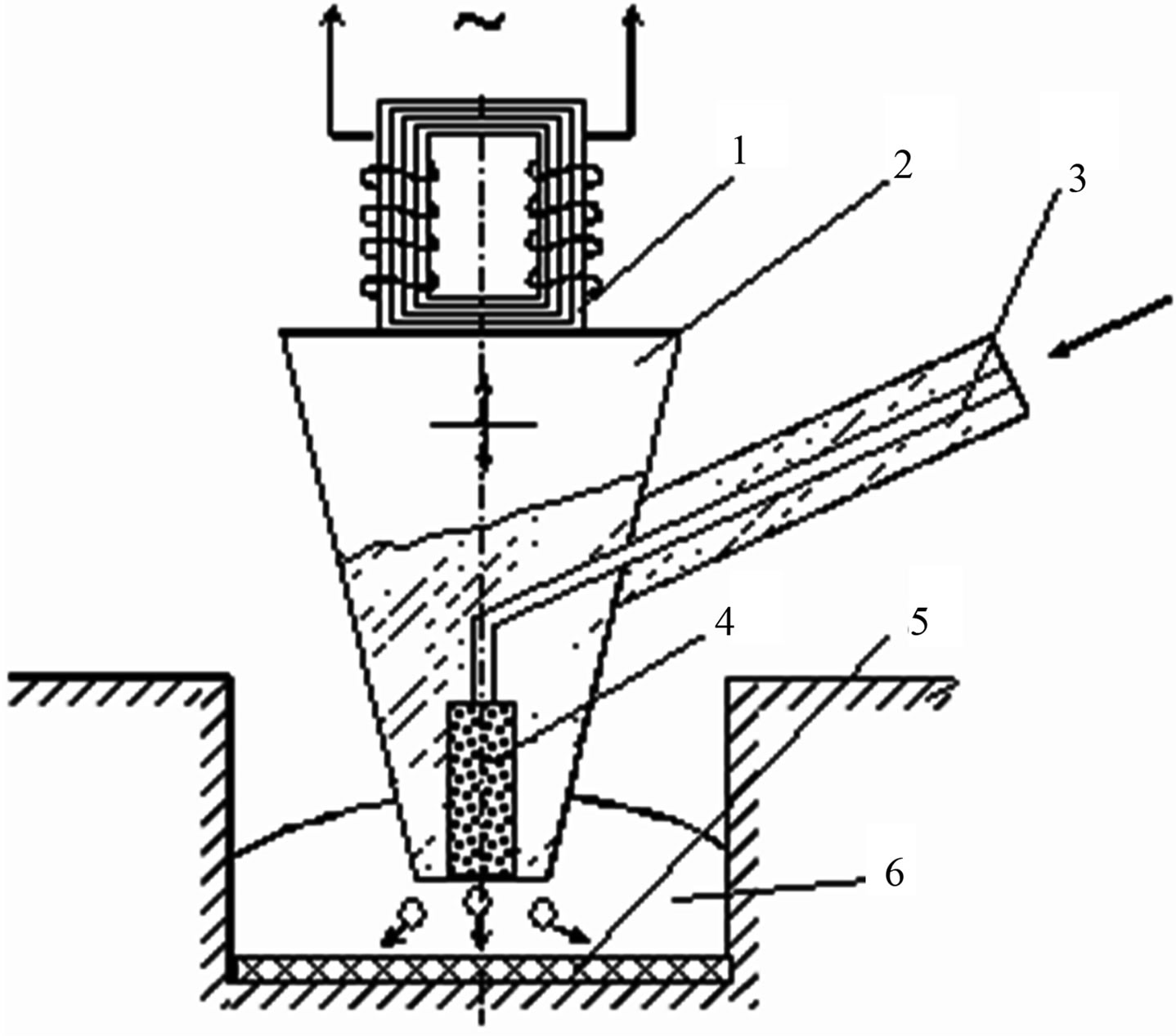
Figure 2. Scheme gas activation in melts.
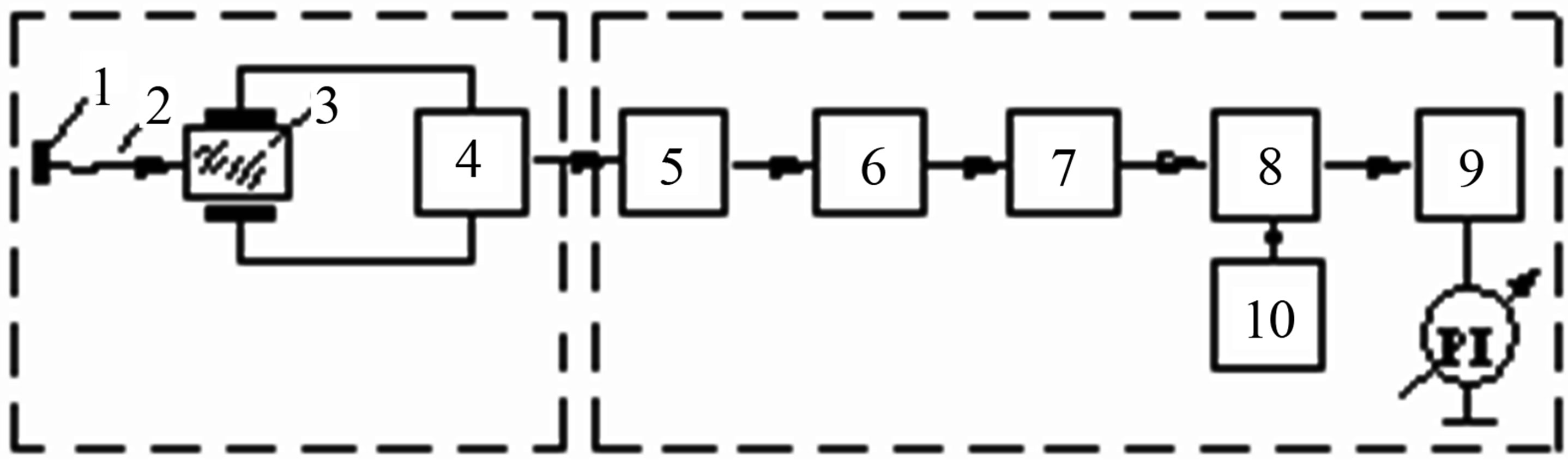
Figure 3. Cavitometr scheme.
 (a)
(a)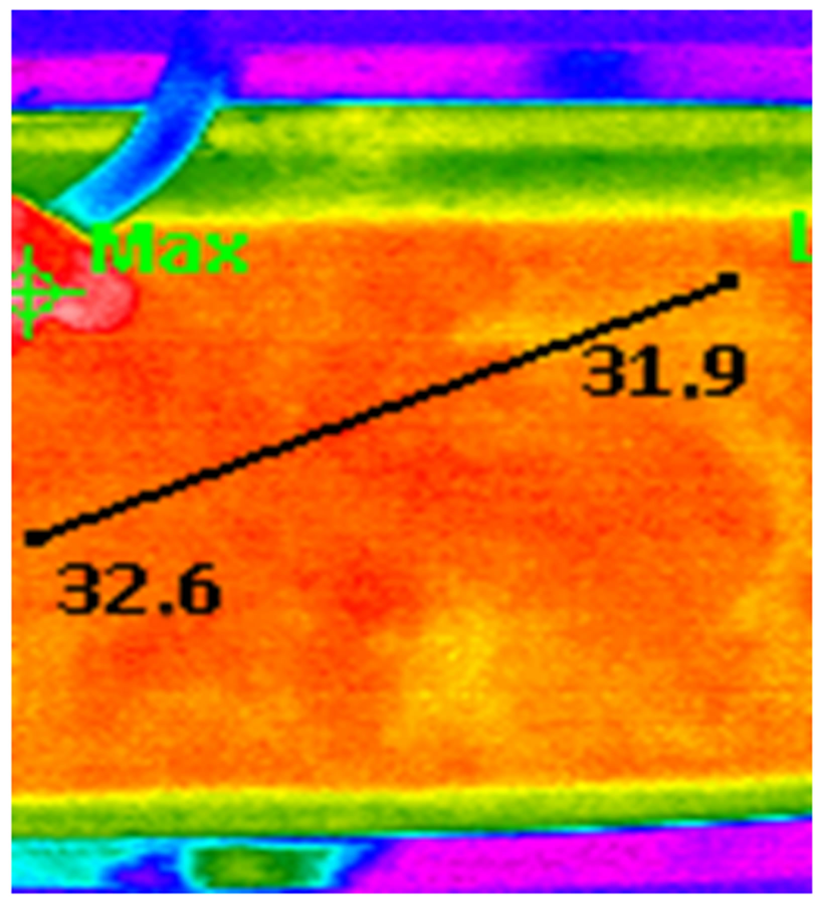 (b)
(b)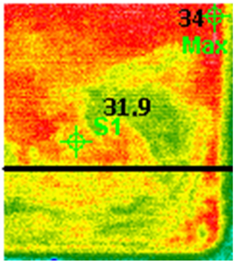 (c)
(c)
Figure 4. Temperature distribution at ultrasound (a), gas activation with ultrasound (b)and thermal fields in liquids (c).
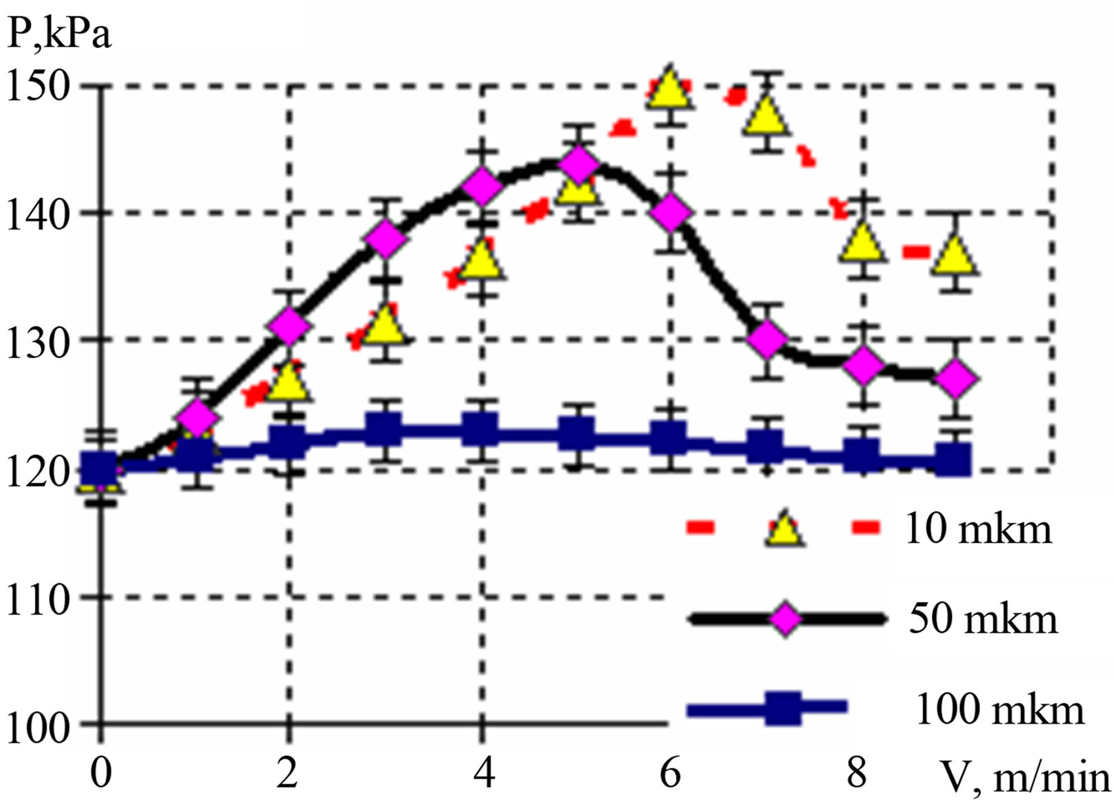
Figure 5. Cavitation pressure vs. speed of gas and sizes of cells.
not slam at levels of US intensity of (2 - 5) × 105 Pa.
4. Conclusion
Gas saturation of liquids of melts raises level of cavitation pressure upon 20% - 25% that allows to intensify US processing, for example, clearings in liquid environments, to increase durability of coupling of metallization with ceramic and glass-ceramic materials, to reduce time of soldering processes, a tinning, metallization, to raise reliability of electronic devices at the expense of reduction of thermal influence.
REFERENCES
- S. P. Kundas, V. L. Lanin, A. P. Dostanko, M. D. Tyavlovsky, V. A. Bursky and V. S. Tomal, “ Ultrasonic Processes in Electronics Production,” Best Print, Minsk, 2003.
- D. Ensminger and L. J. Bond, “Ultrasonics: Fundamentals, Technologies, and Applications,” CRC Press, Boca Raton, 2012.
- T. G. Leighton, “The Acoustic Bubble,” Academic Press, London, 1994.
- H. Harada, H. Yoshida and H. Kato, “The Intensity of MBSL and Chemical Power in Pure Water with Various Dissolved Gases at 2,4 MHz,” Proceeding of the 11th Meeting of the European Society of Sonochemistry, La Grande-Motte, 1-5 June 2008, pp. 163-164.
- O. V. Abramov, “High-Intensity Ultrasonics: Theory and Industrial,” OPA, Amsterdam, 1998.
- V. L. Lanin, “Activation of Soldered Connections in the Process of Formation Using the Energy of Ultrasonic and Electric Fields,” Surface Engineering and Applied Electrochemistry, Vol. 44, No. 3, 2008, pp. 235-240.
- V. L. Lanin, “Activation of Ultrasonic Clearing in the Liquid Environments,” Proceedings of the 4th Conference on Application of Power Ultrasound in Physical and Chemical Processing, Besancon, 22-23 May 2003, pp. 210-213.
- V. L. Lanin, “Cavitation Intensity Measurements in Melts,” Proceeding of the 16th International Symposium on Nonlinear Acoustics,” Moscow, 19-23 August 2002, pp. 1019-1022.