Journal of Electronics Cooling and Thermal Control
Vol.04 No.04(2014), Article ID:52090,9 pages
10.4236/jectc.2014.44013
Numerical Study of Thermal Performance of a Capillary Evaporator in a Loop Heat Pipe with Liquid-Saturated Wick
Masahito Nishikawara1, Hosei Nagano1, Laetitia Mottet2, Marc Prat2
1Department of Aerospace Engineering, Nagoya University, Nagoya, Japan
2INPT, UPS, IMFT (Institute of Fluid Mechanics of Toulouse), Toulouse University, Toulouse, France
Email: nishikawara@prop2.nuae.nagoya-u.ac.jp
Copyright © 2014 by authors and Scientific Research Publishing Inc.
This work is licensed under the Creative Commons Attribution International License (CC BY).
http://creativecommons.org/licenses/by/4.0/


Received 20 October 2014; revised 20 November 2014; accepted 2 December 2014
ABSTRACT
Heat transfer of a capillary evaporator in a loop heat pipe was analyzed through 3D numerical simulations to study the effects of the thermal conductivity of the wick, the contact area between the casing and the wick, and the subcooling in the compensation chamber (CC) on the thermal performance of the evaporator. A pore network model with a distribution of pore radii was used to simulate liquid flow in the porous structure of the wick. To obtain high accuracy, fine meshes were used at the boundaries among the casing, the wick, and the grooves. Distributions of temperature, pressure, and mass flow rate were compared for polytetra-fluoroethylene (PTFE) and stainless steel wicks. The thermal conductivity of the wick and the contact area between the casing and the wick significantly impacted thermal performance of the evaporator heat-transfer coefficient and the heat leak to the CC. The 3D analysis provided highly accurate values for the heat leak; in some cases, the heat leaks of PTFE and stainless steel wicks showed little differences. In general, the heat flux is concentrated at the boundaries between the casing, the wick, and the grooves; therefore, thermal performance can be optimized by increasing the length of the boundary.
Keywords:
Capillary Evaporator, Loop Heat Pipe, Numerical Simulation, Pore Network Model, Two-Phase Heat Transfer

1. Introduction
Loop heat pipes (LHPs) and capillary pumped loops (CPLs) have attracted attention as advanced thermal control devices of spacecrafts, electronic devices, etc. The LHP and CPL require no external power to drive working fluids because of the capillary pressure generated in a porous structure in the evaporator, and they have high heat-transfer capabilities because heat transport is associated with phase changes between liquid and vapor (Figure 1(a)). Operating principles and characteristics are explained in detail elsewhere [1] [2] .
The thermal performance of these devises is significantly affected by the design of the evaporator, and several studies of heat and mass transfer in capillary evaporators have been reported [3] -[13] . Fluid in the wick takes one of two principal forms: at low heat loads, the wick is completely filled with liquid, whereas at high heat loads, the wick contains fluid in a two-phase liquid-vapor state. Since it is complicated to propose an optimum geometry of the evaporator for the two widely different conditions, this paper focuses on the first condition. Numerical studies on heat transfer with saturated wicks have been performed [3] -[9] . In [5] , a quasi-3D numerical model was developed on the basis of Darcy’s law and energy conservation in the evaporator, including liquid in the compensation chamber (CC), the wick, the groove, and the casing; the model was used to obtain distributions of temperature, pressure, and velocity. In [6] , a 3D simulation using the lattice Boltzmann method was presented, and details of flow and heat transfer in the porous structure were obtained.
A high-performance evaporator requires high-efficiency heat exchange between the casing of the heating surface and the vapor transferred to the condenser. In addition, heat leaks to the CC must be small because the saturated state in the CC controls the state of the LHP. Therefore, evaporator designs for thermal performance can be discussed in terms of the trade-off between the heat-transfer coefficient and heat leaks to the CC. This approach has been addressed in [14] . In our previous study, polytetrafluoroethylene (PTFE) wicks, with a bulk thermal conductivity of 0.25 W/m∙K, were applied in an attempt to decrease heat leaks to the CC [8] [15] [16] . Moreover, there is a requirement also for the evaporator to transfer the maximum heat load. To increase the heat-transfer amount reaching the capillary limit, the reduction of the pressure loss by the fluid flow should be considered. However, this point is not included in this paper.
In this study, a 3D numerical model of an LHP evaporator with the wick fully saturated with liquid is developed. The purpose was to find a guide for a design that attains geometric optimization in terms of the capillary evaporator’s thermal performance. Focus has been provided on how the thermal performance of the evaporator is affected by the wick’s thermal conductivity, the contact area between the casing and the wick, and the subcooling in the CC. Note that, in this study, situations wherein the wick contains fluid in two-phase vapor-liquid states are not considered; those situations have been addressed elsewhere [10] -[12] . In Section 2, the governing equations and the porous characteristics of the wick are described. In Section 3, our numerical procedure is discussed. Finally, in Section 4, computational results are presented. Comparison of PTFE with stainless steel as a representative material of metal wick is discussed specially.
2. Numerical Model
This section presents our numerical model for heat and mass transfer in the evaporator. Figure 1(b) shows the computational domain, which corresponds to the area surrounded by the red dashed line in Figure 1(a). Thewick contains grooves, as observed in Figure 1(b). The pore network model (PNM) in [9] [11] [12] was applied here to determine how liquid flow in the wick is affected by the pore radius distribution in the porous media.
Figure 1(c) shows the PNM. The PNM divides the porous structure into two parts-pores and throats. In our case, the pores were spherical and the throats were cylindrical. The radii of the pores and throats together with the lengths of the throats characterize the porous structure of the wick, which includes pore radius, porosity, and

Figure 1. (a) Schematic of a loop heat pipe, (b) computational domain, and (c) representation of pore network model for fluid analysis in the wick.
permeability. Using this simple model, the PNM can include more pores and calculate over a larger porous media than the lattice Boltzmann method. Energy conservation in other components of the LHP was excluded, allowing us to easily determine heat-transfer only in the evaporator.
The main assumptions used in the model were as follows: 1) grooves were filled with saturated vapor at constant temperature and pressure; 2) the bulk solid and fluid in the wick were in local thermal equilibrium; 3) the fluid was incompressible; 4) fluid properties were temperature dependent; 5) the liquid-vapor interface had no thickness; 6) the process was at steady state; and 7) the effects of gravity and thermal radiation were negligible.
2.1. Governing Equation
In the PNM, mass flow rate  in the throat between pores
  and
and  is expressed as follows,
 (1)
(1)
where,  is flow resistance in the throat,
  is kinematic viscosity coefficient of liquid,
  is pressure in a pore. Assuming Poiseuille flow, the flow resistance is given by:
 (2)
(2)
where,  and
and  are radius and length of the throat, respectively. By considering mass conservation at pore
 , system of linear equations is obtained,
 (3)
(3)
Energy conservation in the wick, including conduction and convection, can be written as
 (4)
(4)
and heat conduction by the evaporator casing is given by
 (5)
(5)
In Equations (4) and (5),  is the isobaric specific heat of the liquid,
  is temperature,
  is thermal conductivity of the casing, and
  is the effective thermal conductivity of the wick filled with liquid. The latter was obtained by volume averaging the thermal conductivities of the bulk solid
  and liquid
  each appropriately weighted with the porosity
 :
:
 (6)
(6)
Liquid evaporate at the interface between the wick and the grooves, which is defined as  interface. The
  interface is shown in Figure 2. The mass flow rate generated by evaporation
  is expressed by
 (7)
(7)
 (8)
(8)
where  is the direction normal to the
  interface,
  is the interfacial heat-transfer coefficient calculated by using the equation in [17] ,
  is the temperature of the grooves,
  is the cross-sectional area, and
  is the latent heat of the working fluid. The temperature in the grooves was assumed to be constant at the saturation temperature. The saturation temperature was calculated from the pressure in the grooves and the
  saturation curve of the working fluid. The pressure loss from the grooves to the CC
  was calculated from the total mass flow rate in the wick, assuming Poiseuille flow in a circular pipe, as presented in [18] . The pressure in the grooves was obtained from
 (9)
(9)

Figure 2. Liquid-vapor interface (Γ interface, orange area) and region of fine mesh (volime in dotted line). (a) front view and (b) rear view.
where  is the pressure in the CC. The temperature and pressure in the CC were not calculated in this study. The assumptions of constant temperature and saturation pressure were imposed to allow simple calculations of only the heat transfer in the evaporator. The other boundary conditions were those commonly used in previous studies: 1) uniform heat flux at the heating surface
  (Neumann boundary condition); 2) thermal connection by contact thermal resistance of 10,000 W/m2∙K used in [19] at the casing-wick contact surface
 ; 3) convective boundary at the bottom of the wick
  with a heat-transfer coefficient of 100 W/m2∙K used in a previous study [13] (Robin boundary condition); 4) constant pressure
  at the bottom of the wick
  (Dirichlet condition); 5) impervious walls at
  and
and ; 6) adiabatic conditions at
  and at the casing-groove interface; and 7) periodic boundary conditions at
  and
and .
.
2.2. Representation of Porous Structure
In the PNM, characteristics of the porous structure can be established by setting dimensions for voids―the radius of each pore , the radius of each throat
 , and the length of each throat
  (see Figure 1(c)) ―which control the porosity, permeability, and pore radius distribution, respectively. In this study, a polytetrafluoroethylene (PTFE) wick [16] , for which the porosity and permeability are 0.34 and 2.0 × 10⁻¹⁴ m2, respectively, is modeled. The mode and maximum pore radius were 1.2 and 2.1 μm, respectively. The throat radius was determined by using a log-normal probability density function to fit the pore radius distribution, which was measured by mercury porosimetry [20] . A mercury porosimeter can measure a pore radius distribution when the capillary pressure balances. In the PNM, the capillary pressure is expressed in terms of the throat’s radius. Therefore, in the PNM, the measured pore radius distribution corresponds to the radius distribution of the throat. Figure 3 compares measured and calculated distributions of pore radii. In the figure, the y-axis contains the pore volume normalized by its maximum. The distribution of throat radii agrees well with the measured distribution of pore radii. To determine the permeability of the constructed wick, the permeability was calculated as introduced in [12] . The computed permeability agreed with the measured permeability within 2%. All the main porous characteristics were in good agreement with measured values. The representation of porous characteristics is presented in [9] . Once the porous structure was constructed, it was used in all calculations.
3. Numerical Procedure
The method used to solve the above equations is shown by the flow chart in Figure 4. First, standard finite volume methods were used to solve the combination of Equations (4) and (5) with no mass flow rate. From those results, the mass flow rate at the  interface was calculated, as imposed by the boundary condition in Equation (3). After the pressure field was obtained from Equation (4), mass flow rates in the wick and the LHP, and the pressure drop from the grooves to the CC were calculated. Finally, the updated pressure drop and mass flow rate in the wick were compared with values from previous iterations to judge convergence of the calculation. If convergence was not yet attained, the calculation returned to Equations (4) and (5) with the updated mass flow rate. The above calculation loop was iterated until convergence was obtained.
An energy balance over the entire system can be written as
 (10)
(10)

Figure 3. Comparison of the measured and calculated pore radius distributions. Vertical axes are normalized by the maximum value.

Figure 4. Flow chart of the numerical algorithm.
where,  is heat leak to the CC,
  is heat transferred by phase change, and
  is sensible heat from the inlet to the outlet of the wick. The right side is total amount of applied heat to the evaporator. Each term in the left side is calculated as follows:
 (11)
(11)
 (12)
(12)
 (13)
(13)
The energy balance (Equation (10)) was satisfied with a maximum relative error of less than 1%.
Generally, a mesh size of  is used. However, in case the thermal conductivity of the wick is lower than that of the casing, the temperature gradient in the wick near the boundary among the casing, the wick, and the grooves can be high. Therefore, to calculate with a high degree of accuracy, a finer mesh of
  is used, as shown in Figure 2. The total number of nodes was 10,773,391.
4. Results and Discussion
Calculations were performed for the eight conditions shown in Table 1. The conditions are selected to investi-

Table 1. Calculation conditions using either PTFE or stainless steel wicks.
aThermal conductivity is 0.25 W/m∙K. bSUS is stainless steel and the thermal conductivity is 16 W/m∙K.
gate how the thermal performance of the evaporator was affected by the thermal conductivity of wicks, contact area between wick and casing, and the subcooling of liquid in the CC. The effective thermal conductivities of the PTFE and stainless steel wicks completely filled with liquid were 0.22 and 10.6 W/m∙K, respectively. The contact area between the casing and the wick depends on the width of the grooves ; in Table 1, the contact area is expressed as the percentage of casing cross-sectional area,
 . Subcooling in the CC was used as the liquid temperature in the CC, which was the boundary condition at
 . Other conditions included the following: the heat flux applied to the casing was 0.625 W/cm2, the saturation temperature in the CC was 29.4˚C, and the thermal conductivity of the stainless steel casing was 16 W/m∙K. The working fluid was ethanol.
Figure 5 shows 3D color renderings for pressure and temperature distributions and 2D color renderings of mass flow rate distributions on the x-y plane at  for the PTFE (left) and stainless steel (right) wicks; these results are from calculations 2 and 5 in Table 1. Figure 5(a) shows little difference in the pressure distributions: the maximum pressure was in the grooves, and the minimum pressure was right under the evaporator case at the groove-wick interface. The maximum pressure difference was about 3.5 kPa, which was much less than the capillary pressure (18 kPa) for the largest pore radius. This confirms that it was reasonable to assume that the liquid-vapor interface was at the interface between the wick and the grooves.
In Figure 5(b), the maximum temperature was on top of the casing, and the minimum temperature was at the lowest part of the wick. The casing temperature with the PTFE wick was higher than that with the stainless steel wick. In the model, the saturation temperature in the CC was set directly to study the performance of only the evaporator. In fact, the CC temperature is affected by the heat leak from the evaporator and the subcooled liquid flowing from the liquid line. Therefore, the CC temperature affects the casing temperature, and evaluation of the temperature in the calculation differs somewhat from reality. Note that the color scales are different for the two panels in Figure 5(b). Note also that, although the boundary conditions on the front and rear surfaces differ, there is almost no variation of temperature or pressure in the z-direction in Figures 5(a)-(b).
In Figure 5(c), the two distributions of mass flow rate are very different. For the PTFE wick, the maximum mass flow rate is at the boundary between the casing, the wick, and the grooves, and the variations are large. In contrast, for the stainless steel wick, the variations are small. It seems that the mass flow rate in the PTFE wick is more sensitive to the temperature distribution.
Figure 6 presents calculated results for the response of the evaporator heat-transfer coefficient to changes in contact areas when PTFE and stainless steel wicks were used; these results are from calculations 1 - 6 in Table 1.
The evaporator heat-transfer coefficient  was calculated from
 (14)
(14)
where  is the contact area between the case and wick, and
  is the average temperature on the upper surface of the casing
 . Here, the performance of the evaporator, without the effect of the heat leak to the CC, was evaluated using
  as the amount of heat instead of using the heat load to the evaporator. Figure 6 shows that the evaporator heat-transfer coefficient with the stainless steel wick was approximately 10 times higher than that with the PTFE wick. This indicates that the thermal conductivity of the wick has a large impact on the heat-transfer coefficient of the evaporator. The figure also shows that, for both wicks, the evaporator heat-transfer coefficient increases as the contact area decreases.
Figure 7 presents distributions of heat flux in the y-direction on the contact surface at  for the PTFE and stainless steel wicks; these are results from calculations 2 and 5 in Table 1. Heat flux in negative y-direction is positive along the vertical axis. For both wicks, the maximum heat fluxes occurred at the groove-wick interface, which were at
  and 3.0 mm. The maximum heat flux for the PTFE wick was 12 times larger than that for the stainless steel wick. At the groove-wick interface (
 and 3.0 mm ), high heat flow occurs in the x-direction due to evaporation with a high interfacial heat-transfer coefficient. As a result, the

Figure 5. Renderings of (a) 3D pressure, (b) 3D temperature, and (c) 2D mass flow rate distributions for PTFE wick (left, calculation 2) and for stainless steel wick (right, calculation 5).
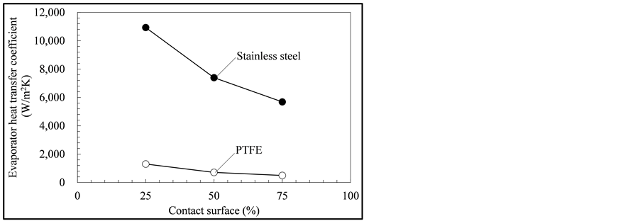
Figure 6. Effect of contact area on evaporator heat-transfer coefficients for PTFE and stainless steel wicks.

Figure 7. Comparison of heat flux distribution along the contact surface between the casing and the wick at  for PTFE and stainless steel wicks.
heat flux concentrates at the boundaries between the casing, the wick, and the grooves. Therefore, the evaporator heat-transfer coefficient is higher when the region of the boundary is larger. Therefore, the thermal performance of the evaporator can be optimized by changing the length of the boundary per unit area of contact surface. In this calculation, the lengths were 0.67, 1.0, and 2.0 mm on contact areas of 75%, 50%, and 25%, respectively. In [8] [21] , increasing the number of grooves, i.e., increasing of the length of the boundary, led to enhance the thermal performance of the evaporator. The pressure loss in the grooves must also be included when considering the LHP performance. The pressure loss depends on groove length and cross-section area, since it can be estimated from flow in a pipe. Thus, geometric optimization of the evaporator for LHP performance can be discussed in terms of the trade-off between the length of the boundary and the geometrical parameters affecting the pressure loss. The optimization theory based on the above will be developed and be verified by LHP experiments in a future work.
Table 2 lists the calculated results at each calculation condition for the evaporator heat-transfer coefficient , the heat transferred by phase change
 , and the heat leak to the CC
 . The two amounts of heat were normalized using the heat load to the evaporator from the rhs of Equation (10). Although the effective thermal conductivities of the two wicks differed by a factor of 48, the heat leaks for the PTFE and stainless steel wicks were almost the same (see results for calculations 1 and 4 in Table 2). Based on an estimate of the heat leak assuming one-dimensional heat conduction in the wick [22] -[25] , the heat leak of the PTFE wick, which has a lower thermal conductivity, is smaller. However, results from the two calculations do not correspond. On the other hand, on data comparison between calculation numbers 3 and 6, the results still provide valid estimations. In [25] , the convection effect of liquid flow in the wick is small because the Peclet number was 0.4. The heat leak can generally be estimated with higher accuracy by 3D analysis; thus, estimates of the heat leak assuming one-dimensional heat conduction in the wick can be less accurate in some cases. The reason may be the temperature distribution in the x-direction, as shown in Figure 5(b), and the formation of a region of superheated liquid in the wick. To estimate the heat leak with high accuracy, it will be necessary to develop a model that considers the above or to solve for the temperature distribution in the wick. In addition, when the entire LHP system evaluated, the heat leak to the CC through the metallic casing must to be considered.
Evaporator heat-transfer coefficients calculated with 5˚ of subcooling (calculations 7 and 8 in Table 2) were smaller than those without subcooling (calculations 2 and 5). This is because the heat leak  was larger due to the lower temperature of the CC by the subcooling; thus, the heat transferred by phase change
  was smaller.
Figure 8 presents the distribution of mass flow rate in the wick?groove interface, as obtained from calculation 7. For this calculation, the length Lz was changed to 1.5 mm , which allows us to more easily view the entire evaporator. On surfaces having heights less than the grooves, the arrows representing mass flow rates in Figure 8 cannot be seen because they point into the wick. This implies that condensation occurred at the interface; this is a heat-pipe effect and has been recognized earlier in [26] . The total mass flow rate by condensation was 8.48% of the total mass flow rate in the evaporator. The effect on the PTFE wick was more noticeable than that on the stainless steel wick. It seems that the heat-pipe effect was larger for the PTFE wick because of the larger temperature distribution in the PTFE wick.
5. Conclusion
The thermal performance of the evaporator in a loop heat pipe using 3D numerical simulations with a pore network model for situations wherein the wick was fully filled with liquid, has been investigated. In particular, how the evaporator’s performance responded to changes in the thermal conductivity of the wick, the contact area
Table 2. Calculated results of evaporator performance at each of the eight conditions listed in Table 1.

Figure 8. Mass flow rate on liquid-vapor interface viewed from rear.
between the casing and the wick, and the subcooling of the CC has been studied. Three-dimensional color renderings of pressure and temperature distributions were presented as well as 2D distributions of mass flow rates. Mass flow rates in the PTFE wick were more sensitive to the temperature distribution than those in the stainless steel wick. The evaporator heat-transfer coefficient for the stainless steel wick was approximately 10 times higher than that for the PTFE wick. On both wicks, heat fluxes concentrated at the boundary among the casing, the wick, and the grooves, and the result of the PTFE wick has larger distribution. The computational results showed that the length of the boundary per unit contact area is an important parameter in geometric optimization of the evaporator with respect to thermal performance. In our 3D analyses, the heat leak to the CC was estimated with high accuracy, and some cases showed small differences in the heat leaks between the PTFE and stainless steel wicks. In addition, the calculated results showed a heat-pipe effect in which evaporation and condensation occurred at the groove-wick interface. This effect was larger for the PTFE wick, which had a larger temperature distribution.
Acknowledgements
This research was partially supported by a Grant-in-Aid for JSPS Fellows (No. 25148) and by JST, PRESTO. A super computer system in the Information Technology center of Nagoya University was used for the calculations. LM and MP gratefully thank CNES and Airbus Defence and Space for their financial support.
References
- David, R., McGlen, R. and Kew, P. (2013) Heat Pipes: Theory, Design and Applications. 5th Edition, Butterworth- Heinemann, Oxford, 234-243.
- Ku, J. (1999) Operating Characteristics of Loop Heat Pipes. SAE Technical Paper, No. 1999-01-2007. http://dx.doi.org/10.4271/1999-01-2007
- Cao, Y.D. and Faghri, A. (1994) Analytical Solutions of Flow and Heat Transfer in a Porous Structure with Partial Heating and Evaporation on the Upper Surface. International Journal of Heat and Mass Transfer, 37, 1525-1533. http://dx.doi.org/10.1016/0017-9310(94)90154-6
- Cao, Y.D. and Faghri, A. (1994) Conjugate Analysis of a Flat-Plate Type Evaporator for Capillary Pumped Loops with Three-Dimensional Vapor Flow in the Groove. International Journal of Heat and Mass Transfer, 37, 401-409. http://dx.doi.org/10.1016/0017-9310(94)90074-4
- Ji, L. and Peterson, G.P. (2011) 3D Heat Transfer Analysis in a Loop Heat Pipe Evaporator with a Fully Saturated Wick. International Journal of Heat and Mass Transfer, 54, 564-574. http://dx.doi.org/10.1016/j.ijheatmasstransfer.2010.09.014
- Li, Q., Zhao, K. and Xuan, Y.M. (2011) Simulation of Flow and Heat Transfer with Evaporation in a Porous Wick of a CPL Evaporator on Pore Scale by Lattice Boltzmann Method. International Journal of Heat and Mass Transfer, 54, 2890-2901. http://dx.doi.org/10.1016/j.ijheatmasstransfer.2011.03.010
- Santos, P.H.D., Oliveira, A.A.M. and Bazzo, E. (2012) Analysis of the Onset of Drying of a Porous Ceramic Wick Applied to a Capillary Pumped Loop and a Loop Heat Pipe. Heat Pipe Science and Technology, an International Journal, 3, 125-151. http://dx.doi.org/10.1615/HeatPipeScieTech.2013006753
- Kuroi, M. and Nagano, H. (2012) The Influence of Groove Shape on Loop Heat Pipe Performance. Heat Pipe Science and Technology, an International Journal, 3, 203-222. http://dx.doi.org/10.1615/HeatPipeScieTech.2013006554
- Nishikawara, M., Nagano, H. and Prat, M. (2013) Evaporator Heat-Transfer Analysis of a Loop Heat Pipe with Low Thermal Conductivity Wicks. Proceedings of the 17th International Heat Pipe Conference, No. 18, Kanpur, 13-17 October 2013.
- Kaya, T. and Goldak, J. (2006) Numerical Analysis of Heat and Mass Transfer in the Capillary Structure of a Loop Heat Pipe. International Journal of Heat and Mass Transfer, 49, 3211-3220. http://dx.doi.org/10.1016/j.ijheatmasstransfer.2006.01.028
- Figus, C., Le Bray, Y., Bories, S. and Prat, M. (1999) Heat and Mass Transfer with Phase Change in a Porous Structure Partially Heated: Continuum Model and Pore Network Simulations. International Journal of Heat and Mass Transfer, 42, 2557-2569. http://dx.doi.org/10.1016/S0017-9310(98)00342-1
- Prat, M. (2010) Pore Network Models for the Study of Transfers in the Porous Wick of Loop Heat Pipes. Heat Pipe Science and Technology, an International Journal, 1, 129-149. http://dx.doi.org/10.1615/HeatPipeSciTech.v1.i2.20
- Chernysheva, M.A. and Maydanik, Y.F. (2012) 3D-Model for Heat and Mass Transfer Simulation in Flat Evaporator of Copper-Water Loop Heat Pipe. Applied Thermal Engineering, 33-34, 124-134. http://dx.doi.org/10.1016/j.applthermaleng.2011.09.025
- Nishikawara, M. and Nagano, H. (2012) Study on Evaporator Heat Transfer Characteristics of a Miniature Loop Heat Pipes with Low Thermal Conductivity Wicks. Proceedings of the 3rd International Forum on Heat Transfer, No. IFHT2012-013, Nagasaki, 13-15 November 2012.
- Nagano, H., Fukuyoshi, F., Ogawa, H. and Nagai, H. (2011) Development of an Experimental Small Loop Heat Pipe with Polytetrafluoroethylene Wicks. Journal of Thermophysics and Heat Transfer, 25, 547-552. http://dx.doi.org/10.2514/1.T3614
- Nishikawara, M. and Nagano, H. (2014) Parametric Experiments on a Miniature Loop Heat Pipe with PTFE Wicks. International Journal of Thermal Sciences, 85, 29-39. http://dx.doi.org/10.1016/j.ijthermalsci.2014.05.016
- Carey, V.P. (1992) Liquid-Vapor Phase-Change Phenomena. Taylor & Francis, London, 112.
- Nishikawara, M., Nagano, H. and Kaya, T. (2013) Transient Thermo-Fluid Modeling of Loop Heat Pipes and Experimental Validation. Journal of Thermophysics and Heat Transfer, 27, 641-647. http://dx.doi.org/10.2514/1.T3888
- Kaya, T., Pérez, R., Gregori, C. and Torres, A. (2008) Numerical Simulation of Transient Operation of Loop Heat Pipes. Applied Thermal Engineering, 28, 967-974. http://dx.doi.org/10.1016/j.applthermaleng.2007.06.037
- Allen, T. (1997) Particle Size Measurement, Surface Area and Pore Size Determination. 5th Edition, Chapman and Hall, New York, 149.
- Riehl, R.R. and Dos Santos, N. (2008) Loop Heat Pipe Performance Enhancement Using Primary Wick with Circumferential Grooves. Applied Thermal Engineering, 28, 1745-1755. http://dx.doi.org/10.1016/j.applthermaleng.2007.11.005
- Maidanik, Y.F., Fershtater, Y.G. and Solodovnik, N.N. (1994) Design and Investigation of Methods of Regulation of Loop Heat Pipes for Terrestrial and Space Applications. Society of Automotive Engineering Technical Paper, No. 941407. http://dx.doi.org/10.4271/941407
- Kaya, T. and Hoang, T.T. (1999) Mathematical Modeling of Loop Heat Pipes and Experimental Validation. Journal of Thermophysics and Heat Transfer, 13, 314-320. http://dx.doi.org/10.2514/2.6461
- Singh, R., Akbarzadeh, A., Dixon, C. and Mochizuki, M. (2009) Theoretical Modeling of Miniature Loop Heat Pipe. Heat and Mass Transfer, 46, 209-224. http://dx.doi.org/10.1007/s00231-009-0504-y
- Bai, L.Z., Lin, G.P., Zhang, H.X. and Wen, D.S. (2009) Mathematical Modeling of Steady-State Operation of a Loop Heat Pipe. Applied Thermal Engineering, 29, 2643-2654. http://dx.doi.org/10.1016/j.applthermaleng.2008.12.040
- Figus, C., Bories, S. and Prat, M. (1996) Investigation and Analysis of a Porous Evaporator for a Capillary Pumped Loop. Proceedings of the Engineering Systems and Design and Analysis Conference, Vol. 8, Montpellier, 1-4 July 1996, 99-106.