Journal of Electronics Cooling and Thermal Control
Vol.04 No.03(2014), Article ID:49447,7 pages
10.4236/jectc.2014.43009
Forced Convection Heat Transfer Coefficient and Pressure Drop of Diamond-Shaped Fin-Array
Shigeki Hirasawa*, Atsushi Fujiwara, Tsuyoshi Kawanami, Katsuaki Shirai
Department of Mechanical Engineering, Kobe University, Kobe, Japan
Email: *hirasawa@kobe-u.ac.jp
Copyright © 2014 by authors and Scientific Research Publishing Inc.
This work is licensed under the Creative Commons Attribution International License (CC BY).


Received 25 July 2014; revised 25 August 2014; accepted 2 September 2014

ABSTRACT
Forced convection cooling of fins on a high-temperature wall has been used to cool high-power electronic devices. We numerically calculated and experimentally measured the forced convection heat transfer coefficient and pressure drop of a diamond-shaped fin-array with water flow in this study, which had been reported to have a self-induced flip-flop flow phenomenon. Although the flip-flop flow phenomenon occurred in calculations, it was not observed in experiments. The heat transfer and pressure drop of the diamond-shaped fin-array could be estimated with equations for turbulent flow in tubes.
Keywords:
Forced Convection, Heat Transfer Performance, Diamond-Shaped Fin, Flip-Flop Flow

1. Introduction
The heat density of high-load electronics, such as high-performance servers and the inverters used in vehicles, has been increasing as a result of higher processing speeds and higher power outputs. The method used to cool electronic devices depends on the level of heat generation and the operating environment, whereas available methods include natural convection cooling [1] , forced convection cooling, and heat pipe cooling [2] . Forced convection cooling is used most often because of its practical advantages in cost and performance. For these reasons, we have been developing forced convection cooling technologies to cool high-power electronic devices [3] . Pin-fin arrays have been studied to enhance forced convection heat transfer in a wide variety of applications, such as heat exchangers and electrical devices. Pin-fin arrays usually consist of a number of cylinders attached perpendicularly to a high-temperature wall with a coolant fluid passing a cross flow over the cylinders. Tsuzuki et al. [4] studied an S-shaped fin-array and reported a method of calculating heat transfer in the fin-array. Tanda [5] studied heat transfer and pressure drop in a diamond-shaped fin-array with a leading angle of 90˚. Umeda et al. [6] [7] reported experimental results obtained from a self-induced flip-flop flow phenomenon in diamond- shaped cylinder bundles with a leading angle of 30˚. The flip-flop flow oscillation promoted fluid mixing and had the potential to enhance convection heat transfer. However, they did not present experimental results for convection heat transfer in a diamond-shaped fin-array with flip-flop flow oscillation.
In this work, we numerically calculated and experimentally measured the forced convection heat transfer coefficient and pressure drop of a diamond-shaped fin-array with water passing a cross flow over the fin-array.
2. Numerical Calculation Method
We used a 3-dimensional thermo-fluid computation code called “STAR-CCM+” [8] in this work to calculate flow velocity and temperature distributions in a water flow around a diamond-shaped fin-array. We used the finite volume method for the numerical calculations. The conditions of incompressible fluid, unsteady turbulent flow with the large eddy simulation (LES) model, constant properties, and discretization with polyhedralmesh were used in the calculations. Figure 1 outlines the calculation conditions. The length was 66.3 mm in the x direction, the width of the flow region was 20.7 mm in the y direction, and the thickness was 2 mm in the z direction. The diamond-shaped fins were in a staggered array with six rows in the x direction and five rows in the y direction. The leading angle of the diamond-shaped fin was 30˚, their width was 2.07 mm in the y direction, and their length was 7.73 mm in the x direction. The width of the grooves between the fins was w = 2 mm in the flow direction of 15˚ was different from that in the x direction. We only calculated the temperature distribution in the fluid between the spaces created by fins and did not calculate the temperature distribution in the fins. The main reason for this was to understand the convection heat transfer coefficient for basic boundary conditions with the constant wall temperature of fins. The surface temperature of the fins was Tw = 40˚C. The flow boundary condition at the surface of the fins had no-slip wall. The boundary condition for the outside wall of the flow region was symmetrical except for the inlet and outlet regions. The fluid was water with an inlet temperature of Ta = 20˚C, density of r = 998 kg/m3, specific heat capacity of Cp = 4180 J/(kg·K), viscosity of m = 8.89 × 10⁻⁴ (Pa·s), and thermal conductivity of l = 0.62 W/(m·K). The time step of unsteady calculation was 0.001 s, the number of iterations at each time step was 20, and the flow velocity and temperature distributions were obtained after more than 0.1 s with less than 0.2% change in the average heat flux from the outside wall of the fins. The transient local heat flux from the outside wall of the fins changed periodically because of the flip-flop flow phenomenon. The inlet velocities were uin = 1, 3 and 10 m/s, which corresponded to the Reynolds number of Re = (rud/m) = 8980, 26,900 and 89,800 using average the velocity in grooves u = 2uin, and the hydraulic diameter d = 2w of grooves with the width w between the fins.
3. Calculation Results
Figure 2 has the calculated results for fluid flow velocity at a transient time (t = t0) in the center cross section for
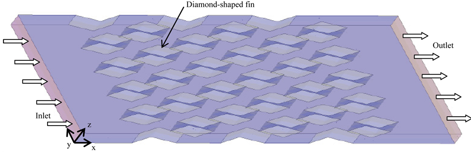
Figure 1. Calculation condition.
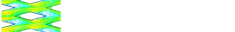
the inlet velocity of uin = 3 m/s and Re = 26,900. The fluid flow caused separation behind the diamond-shaped fins and the flow pattern was not symmetrical in the y direction especially behind the fin-array near the outlet. Figure 3 shows the fluid flow velocity and temperature distributions at time (t = t0 − 0.02 s), which is 0.02 s before from that for Figure 2. The separation and fluid flow behind the diamond-shaped fins are different from those in Figure 2 and there is a flip-flop flow phenomenon as was reported by Umeda et al. [6] [7] . Figure 4 shows the flow velocity distribution near the fin in the (3, 3)-row at time (a) t = t0 − 0.012 s, (b) t = t0 − 0.008 s, (c) t = t0 − 0.004 s, and (d) t = t0. We can see the change in the flow direction of the flip-flop flow phenomenon and the change in the flow direction does not occur at the same time for all fins.
Figure 5 has the temperature distributions at time (t = t0) in the center cross section. The temperature of the fluid increases along the flow direction due to convection heat transfer from the fins.
Figure 6 plots the local heat flux distribution q on the surface around the fin in the (3, 3)-row at time (t = t0). The local heat heat flux q is high along the upstream side of the fin especially at its leading and flank edges. The local heat heat flux q is low along the downstream side of the fin because of the separation of fluid flow. Figure 7 plots the average heat flux qave around the fins in the n-th row along the row in the x direction at time (t = t0).
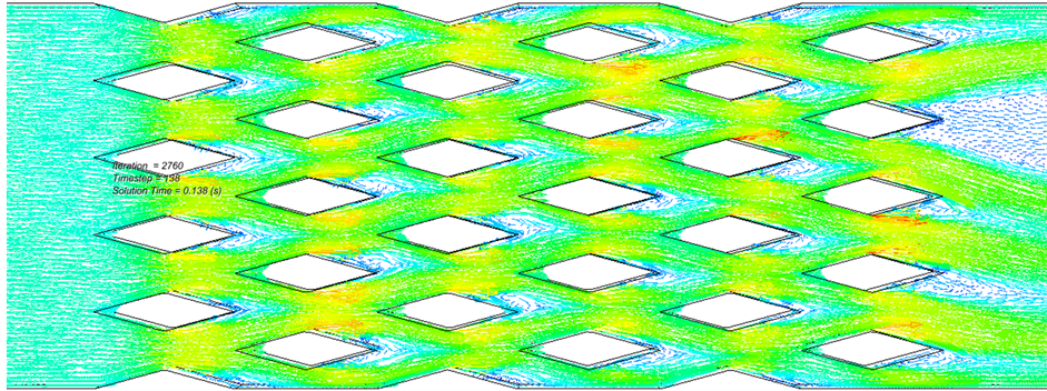

Figure 2. Flow velocity distribution (t = t0, Re = 26,900).

Figure 3. Flow velocity distribution (t = t0 − 0.02s, Re = 26,900).
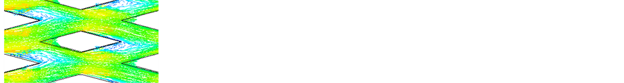

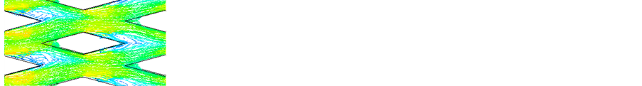
 (a) t = t0 − 0.012 s (b) t = t0 − 0.008 s (c) t = t0 − 0.004 s (d) t = t0
Figure 4. Flow velocity distribution near fin in (3, 3)-row (Re = 26,900).
 20 21Temperature (˚C)
Figure 5. Temperature distribution (t = t0, Re = 26,900).
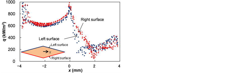
Figure 6. Local heat flux distribution around fin in (3, 3)-row (t = t0, Re = 26,900).
The average heat flux qave around the fins changes about 10% because of the flip-flop flow phenomenon. The average heat flux qave around the fin in the first row is small because flow velocity is small on the upstream side of the fins.
Figure 8 and Figure 9 show the fluid flow velocity at a transient time in the center cross section for the inlet velocities of uin = 1 and 10 m/s (Re = 8980 and 89,800). The flow velocity distributions are different from those in Figure 2 (uin = 3 m/s, Re = 26,960) but the same flip-flop flow phenomena occur.
Average heat transfer coefficient
 and Nusselt number Nu (=ad/l) were obtained from average heat flux qave for all fins in the calculation region and the temperature difference between the wall of the fins Tw = 40˚C and inlet of fluid Ta = 20˚C, the hydraulic diameter d of grooves, and thermal conductivity l.

Figure 7. Average heat flux of fins along row (t = t0, Re = 26,900).


Figure 8. Flow velocity distribution (Re = 8980).


Figure 9. Flow velocity distribution (Re = 89,800).
Figure 10 plots the relation between Reynolds number Re and Nusselt number Nu for our calculated results with the triangles “D”. Nusselt number Nu for turbulent flow in a tube is known to be calculated with Equation (1) [9] .
 (1)
(1)
Here, Pr is the Prandtl number of fluid (Pr = 6.0). The line in Figure 10 indicates the relation with Equation (1). Our calculated results agree with the relation in Equation (1).
Figure 11 plots the relation between Reynolds number Re and the pressure drop through fins DP for our calculated results with the triangles “D”. Pressure drop DP for turbulent flow in a tube with the entrance and exit pressure loss can be calculated with Equation (2) [9] .
 (2)
(2)
Here, k is the friction coefficient with the function of the Reynolds number (k = 0.031, 0.024, and 0.013 at Re = 8980, 26,960, and 89,800 [9] ), Kc is the sum of entrance and exit loss coefficients (Kc = 1), r is fluid density, and u is the flow velocity. The line in Figure 11 plots the relation with Equation (2). Our calculated results agree with the relation in Equation (2). Therefore, we found that heat transfer and pressure drop in a diamond- shaped fin-array could be estimated with equations for turbulent flow in tubes though they had the flip-flop flow phenomenon.
4. Experimental Apparatus
Figure 12 outlines the experimental apparatus. The test section was placed in an acrylic case (170 mm ´ 120
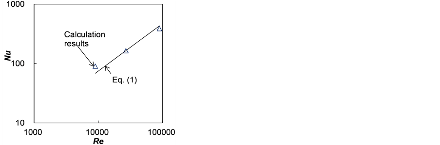
Figure 10. Calculation results of relation between Nusselt number and Reynolds number.
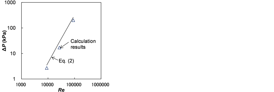
Figure 11. Calculation results of relation between pressure drop and Reynolds number.
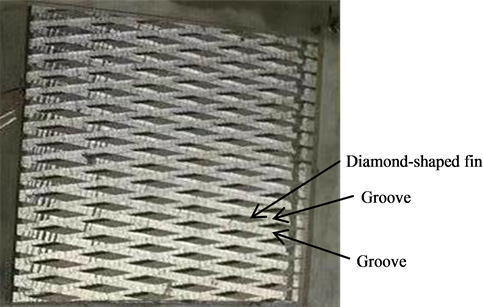
mm ´ 30 mm) and the excess spaces in the case were filled with dummy acrylic blocks. Water at a temperature of 15˚C was supplied to the test section from a chiller after the flow rate was measured. Figure 13 shows the test fin-array. The diamond-shaped fin-array was made out of a copper block (70 mm ´ 70 mm ´ 15 mm) by cutting crossed grooves w = 2 mm in width, 2 mm in depth, and 4 mm in pitch. The leading angle of the diamond- shaped fins was 30˚. The copper block was heated with three cartridge heaters (5 mm in diameter and a total heating rate of 200 W). The temperatures of the copper block and inlet water were measured with T-type thermocouples. The flow velocities u = 3.3 and 5 m/s in the grooves, which corresponded to the Reynolds number of Re = (rud/m) = 7410 and 11,200 using the hydraulic diameter d = w of rectangular grooves between the fins.
5. Experimental Results
The water flow pattern between the fins could be observed with tiny particles in water. The flip-flop flow phenomenon was not observed in our experiment under any experimental conditions. The reason for this is that the fluid space behind the fin-array was not enough to generate oscillation. Figure 14 plots the relation between Reynolds number Re and Nusselt number Nu in our experimental results with the circles “o”. The line in Figure 14 indicates the relation with Equation (1) for turbulent flow in a tube. Our experimental results agreed with the relation in Equation (1) which was similar to the calculated results in Figure 10.
6. Conclusions
We numerically calculated and experimentally measured the forced convection heat transfer coefficient and pressure drop of a diamond-shaped fin-array with water flow. The following results were obtained.
1) The flip-flop flow phenomenon occurred in calculations but was not observed in experiments.

Figure 12. Experimental appatatus.
 (a) (b)
Figure 13. Test fin-array. (a) Schematic view; (b) Top view.
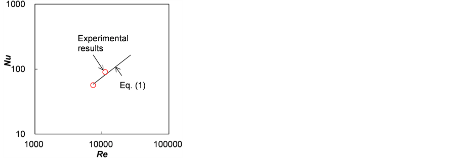
Figure 14. Experimental results of relation between Nusselt number and Reynolds number.
2) The heat transfer coefficient and pressure drop of the diamond-shaped fin-array could be estimated with equations for turbulent flow in tubes even though they had the flip-flop flow phenomenon.
References
- Nakazato, N., Hirasawa, S. and Mato, T. (1998) Natural Convection Cooling in Vertical Finned Plates in a Cabinet for Communication Equipment. IEICE Transactions on Electronics, 81, 421-426.
- Toyoda, H. and Kondo, Y. (2013) Effect of Non-Condensable Gas Leakage on Long Term Cooling Performance of Loop Thermosyphon. Journal of Electronics Cooling and Thermal Control, 3, 131-135. http://dx.doi.org/10.4236/jectc.2013.34014
- Atarashi, T., Tanaka, T., Tsubaki, S. and Hirasawa, S. (2014) Calculation Method for Forced-Air Convection Cooling Heat Transfer Coefficient of Multiple Lows of Memory Cards. Journal of Electronics Cooling and Thermal Control, 4, (Accepted to Be Published).
- Tsuzuki, N., Utamura, M. and Ngo, T.L. (2009) Nusselt Number Correlations for a Microchannel Heat Exchanger Hot Water Supplier with S-Shaped Fins. Applied Thermal Engineering, 29, 3299-3308. http://dx.doi.org/10.1016/j.applthermaleng.2009.05.004
- Tanda, G. (2001) Heat Transfer and Pressure Drop in a Rectangular Channel with Diamond-Shaped Elements. International Journal of Heat and Mass Transfer, 44, 3529-3541. http://dx.doi.org/10.1016/S0017-9310(01)00018-7
- Umeda, S., Hasegawa, S. and Yang, W.J. (2005) Occurrence of Flip-Flop Flows in Diamond-Shaped Cylinder Bundles. Transaction of JSME B, 71, 2949-2955.
- Umeda, S. and Yang, W.J. (2004) Effects of Mesh-Induced Upstream Turbulence on Flip-Flop Flow inside Diamond- Shaped Cylinder Bundles. Proceedings of ASMEHT-FED 2004 Conference, HT-FED2004-56140.
- STAR-CCM+ Product Information (CD-Adapco Co.). http://www.cd-adapco.com/products/STAR-CCM_plus/index.html
- Holman, J.P. (1989) Heat Transfer. McGraw-Hill Book Co., New York.

*Corresponding author.