Open Journal of Antennas and Propagation
Vol.04 No.03(2016), Article ID:70364,10 pages
10.4236/ojapr.2016.43010
On the Design of Plus Slotted Fractal Antenna Array
Mandeep Kaur, Jagtar Singh Sivia
Yadawindra College of Engineering, Punjabi University Guru Kashi Campus, Bathinda, India

Copyright © 2016 by authors and Scientific Research Publishing Inc.
This work is licensed under the Creative Commons Attribution International License (CC BY 4.0).
http://creativecommons.org/licenses/by/4.0/


Received: August 1, 2016; Accepted: September 2, 2016; Published: September 5, 2016
ABSTRACT
A new technique which is a combination of fractal antenna and array antenna is presented to design Plus Slotted Fractal Antenna Array (PSFAA) in this paper. PSFAA with corporate feed operates at 2.5 GHz frequency. PSFAA is designed on FR4 substrate material with permittivity 4.4 and height 1.6 mm. PSFAA is designed up to 2nd iteration. High Frequency Structure Simulator (HFSS) software is used for simulation of PSFAA. The proposed antenna array operates at three bands with five frequencies 2.5 GHz, 4.1 GHz, 6.9 GHz, 7.4 GHz and 8.2 GHz. Simulated Return losses results of proposed PSFAA are −22.15 dB, −19.44 dB, −25.21 dB, −10 dB, −12.45 dB at above frequencies respectively. It has a gain of 9.22 dB at resonant frequency 2.5 GHz whereas conventional antenna array has a gain of 5.15 dB at resonant frequency 2.5 GHz. Return losses and gain of PSFAA also improved from conventional antenna array at various resonant frequencies.
Keywords:
Plus Shaped Slots, Multiband, Corporate Feed, Plus Slotted Fractal Antenna Array (PSFAA), Gain

1. Introduction
Antenna can be defined as a device used for radiating and receiving electromagnetic waves. Substrate, patch and ground plane are the three basic layers of any Microstrip Patch Antenna (MPA). Substrate is the middle layer that is sandwiched between patch and ground. Substrate material has different values of permittivity. In modern antenna technology, patch antennas plays important role [1] [2] . Attractive features of patch antennas are such as light weight, low profile, simple to manufacture and low cost [3] but conventional patch antennas have some disadvantages such as narrow bandwidth, low efficiency and low gain [4] . Various feeding techniques [5] are used to enhance the gain and bandwidth of patch antennas. Limited space problem is occurring because different antennas are required for different applications. This problem is solved by using multiband antenna which can operate on many frequencies. For multiband operations, fractal antennas are used [6] . Similar geometry of patch when connected with a single feed line is called array [7] . Various performance parameters of the antenna like scanning the beam of an antenna system, directivity and gain are improved by using array technology in antenna communication [8] . In this paper, two broad technique of antenna are combined. One is array and another is fractal geometry named as Fractal Antenna Array (FAA) [9] . The main parameters like VSWR, gain and return loss are improved by using FAA [10] . There are different methods to feed array antenna but in this paper corporate feeding method is used. Tapered lines or Quarter wavelength transformer can be used in corporate feed method [11] - [13] . Using this method, feed of each element is more controllable. QWT method is used in shape beam array, multi beam array and phase beam array [8] . Fractal and array antennas have various use in meteorological satellite and military applications, PTP communication in US military, radar and navigation services ,Wi-Fi, UMTS applications, etc [10] . Simulated results of PSFAA are obtained using HFSS software [14] . This paper presents a design which is obtained by mixing two techniques and proposed PSFAA work at resonant frequency 2.5 GHz.
From the literature, it is clear that rectangular antenna array is designed at a frequency of 2.5 GHz with gain of 2.648 dB [7] . A carpet antenna array operates at five frequencies 6.29 GHz, 6.9 GHz, 7.46 GHz, 8.48 GHz and 11.07 GHz with maximum gain of 5.48 dB [10] . A rectangular antenna array operating at three frequencies 8.86 GHz, 9.16 GHz and 11.07 GHz with a gain of 7.97 dB is designed. These antenna arrays suffer from the limitation of less gain. Thus in this paper, the concept of fractal antenna with combination of antenna array is applied to design a plus slotted fractal antenna array with a maximum gain of 10.26 dB.
2. Antenna Design and Configuration
Proposed PSFAA is designed by using following steps:
Step 1: Substrate of proposed PSFAA having 113.5 mm as a width and 57.91 mm as a length respectively. For the design of proposed PSFAA dielectric constant of 4.4, resonant frequency 2.5 GHz and thickness of substrate 1.6 mm is taken. Two similar patch elements are designed on a substrate which having length is 28 mm and width is 35 mm. These values are calculated by using Equations (1)-(4) given in [1] - [3] .
Equation (1) as given in [1] - [3] is used to calculating the width of patch element
 (1)
(1)
In above equation, v0 is the free space velocity. Patch width is calculated 35 mm. Per- mittivity of PSFAA is determined by Equation (2) as given in [1] - [3] .
 (2)
(2)
Extension patch length of PSFAA as described in [1] - [3] is taken from Equation (3).
 (3)
(3)
Actual length of single patch element is obtained from Equation (4) as shown in [1] - [3] .
 (4)
(4)
Length of patch element is found from equation = 28 mm.
Step 2: Two similar patches are designed on substrate in initial design process of PSFAA. Patch has 28 mm length and 35 mm width as given in Table 1.
Step 3: Distance between centre points of two patches of PSFAA is λ/2. A proper distance is maintained between patches so that minimum side lobes are achieve in radiation pattern
Step 4: A plus shape slot of proposed PSFAA is cut from each patch element having 6 mm length and 2 mm width as shown in Table 1. After cutting slots it becomes 1st iteration as shown in Figure 1(b).
Step 5: To connect two patch element of PSFAA corporate feed line is used. Better impedance matching is the great advantage of this feed line. To obtain this between feed and radiating patches, corporate feed procedure contain a matching and quarter

Table 1. Dimensions of PSFAA.

Figure 1. (a) 0th iteration of PSFAA, (b) 1st iteration of PSFAA, (c) 2nd iteration of PSFAA, (d) back view of PSFAA with defected ground.
wave transformers, power divider and coupler.
Step 6: An inset cut of 8 mm length and 6 mm width is taken from the both patches. Feed network is designed with 50 Ω and 70 Ω lines that are used for impedance matching between feed and patches.
Step 7: Defected ground plane of PSFAA is used to signify the performance parameters. Gain, VSWR and return losses are improved by using defected ground. A plus shape slot is cut from ground plane that having 22 mm length and 4 mm width.
Figure 1(a) represents the geometry of conventional antenna array. In Figure 1(b) one plus shape slot is cut from the centre of both patches to make its similar structure to the 1st iteration of antenna array. In 2nd iteration, eight more plus shape slots are cut from both patches as shown in Figure 1(c). Figure 1(d) represents defected ground back view of PSFAA. Fabricated geometry PSFAA with front and back views are shown in Figure 2(a) and Figure 2(b) respectively. Design parameters of PSFAA are shown in Table 1.
3. Results and Discussions
In this section, experimentally measured and simulated results are discussed. Due to mismatching of impedance some power reflected back to input is called return loss. Figure 3 depicts the Return Losses (RL) v/s frequency (GHz) graphs for 0th, 1st and 2nd iteration of proposed PSFAA. 0th iteration of this antenna operates at five frequencies 2.5 GHz, 4.1 GHz, 7.0 GHz, 7.4 GHz and 8.4 GHz with return losses −11.25 dB, −20.02 dB, −17.64 dB, −16.25 dB and −22.09 dB respectively. 1st iteration of proposed PSFAA works at five frequencies 2.5 GHz, 4.1 GHz, 6.9 GHz, 7.4 GHz and 8.3 GHz with return losses −14.93 dB, −10.21 dB, −18.04 dB, −11.56 dB and −17.34 dB. Similarly 2nd iteration works at five frequencies 2.5 GHz, 4.1GHz, 6.9 GHz, 7.4 GHz and 8.2
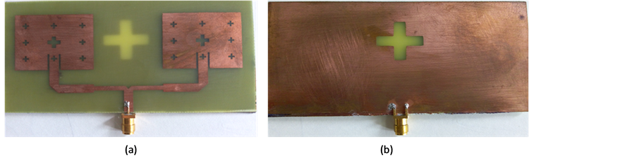
Figure 2. (a) Front and (b) back views of fabricated PSFAA.

Figure 3. RL v/s frequency plot of PSFAA.
GHz with return losses −22.15 dB, −19.44 dB, −25.21 dB, −10.05 dB and −12.45 dB.
Measured results are obtained by using vector network analyzer (MS46322A). A comparison between simulated and experimentally measured results of 2nd iteration of PSFAA is characterized in Figure 4. Simulated and measured results shows some difference between them due to the practical and theoretical results.
When antenna is designed practically there is always a difference between simulated and measured results is seen because simulated results are on the basis of numerical calculations where as measured results are the practical results shown by the antenna. Another factor is dielectric constant which is taken 4.4 for simulated results but practically this dielectric constant may have some variations that’s why simulated and measured results does not show agreement in the frequency range of 8 - 9 GHz. Graphically described the radiations of antenna as a function of space coordinates are called radiation pattern. It is also called 2D Polor plot. Figure 5 described the polar plots of all iterations at resonant frequency 2.5 GHz in E and H plane of PSFAA. From these figures it is clear that 3rd iteration of the proposed antenna has more gain as compared to 0th

Figure 4. RL v/s frequency plot of simulated and measured results of PSFAA.
 (a) (b) (c)
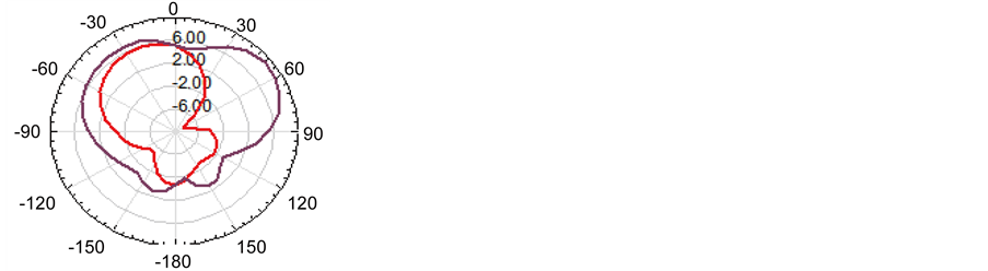
Figure 5. (a) Polar plot of 2nd iteration, (b) polar plot of 1st iteration, (c) polar plot of 0th iteration at a 2.5 GHz.
and 1st iteration of the antenna. Far field patterns of antenna also shows that polar plots have approximately unidirectional properties at 2.5 GHz.
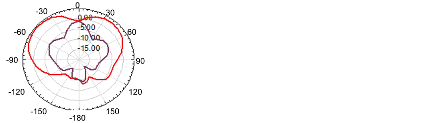
Polar plots for 2nd iteration of this antenna at resonant frequencies 2.5 GHz, 4.1 GHz, 6.9 GHz, 7.4 GHz and 8.2 GHz are shown in Figure 6. From these plots, it is clear that at frequency 2.5 GHz this antenna has a gain of 9.22 dB and maximum gain of 10.26 dB at frequency 6.9 GHz.
Results of 0th, 1st and 2nd iterations at different frequencies 2.5 GHz, 4.1 GHz, 6.9 GHz, 7.4 GHz and 8.2 are compared in the above Table 2. From Table 2, it is clear that return losses and gain of PSFAA are improved as the number of iterations is increased. Proposed PSFAA has maximum gain of 10.26 dB at 6.9 GHz frequency of 2nd iteration. All the parameters of proposed PSFAA are improved by using combination of fractal and array technique.
VSWR factor describes how much impedance matching is done between antenna and transmitter.
 (a) (b)
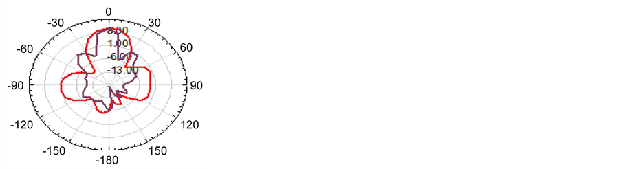
 (c) (d)
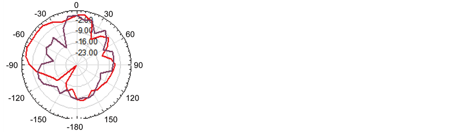 (e)
(e)
Figure 6. (a) Polar plots of PSFAA at frequency 2.5 GHz, (b) 4.1 GHz, (c) 6.9 GHz, (d) 7.4 GHz and (e) 8.2 GHz respectively.
Figure 7 described the VSWR characteristics of PSFAA. 0th iteration has VSWR 1.17, 1.20, 1.46, 1.54 and 1.17 at resonant frequencies 2.5 GHz, 4.1 GHz, 7.0 GHz, 7.4 GHz and 8.4 GHz respectively. 1st iteration has 1.43, 1.89, 1.28, 1.91 and 1.38 at resonant frequencies 2.5 GHz, 4.1 GHz, 6.9 GHz, 7.4 GHz and 8.3 GHz respectively. Similarly 2nd iteration of PSFAA has VSWR 1.16, 1.23, 1.11, 1.91 and 1.62 at resonant frequencies 2.5 GHz, 4.1 GHz, 6.9 GHz, 7.4 GHz and 8.2 GHz respectively. For satisfactory operation of an antenna VSWR should lie between 1 and 2.
Table 3 describes a comparison of PSFAA with other similar type of antenna array available in literature. D. S. Sagne et al. [10] designed carpet antenna array which operates at four resonant frequencies with maximum gain 5.4 dB. Sivia et al. [15] designed RMPAA which operates at three resonant frequencies with 7.97 dB gain. Proposed an-
Table 2. Performance parameters of PSFAA.

Figure 7. VSWR v/s frequency graph of PSFAA.
tenna has more gain (9.2 dB) and works at a five resonant frequencies. Thus proposed antenna array is better than similar types of antenna array available in Table 3.
4. Conclusion
In this paper, PSFAA antenna which is a combination of fractal antenna and array antenna is designed using corporate feeding technique. Proposed PSFAA is designed up
Table 3. Comparison of proposed PSFAA with other research papers.
to 2nd iteration. PSFAA results are improved as the numbers of iterations are increased. Proposed PSFAA operates at five frequencies and has maximum gain 10.26 dB at frequency 6.9 GHz. Thus, this antenna has better gain than the gain of antennas present in literature. This antenna has 9.22 dB, 3.18 dB, 6.67 dB and 5.69 dB at other four respective resonant frequencies which are 2.5 GHz, 4.1 GHz, 7.4 GHz and 8.2 GHz. HFSS is used for simulation and VNA is used for measured results. Plus slotted FAA operates on multi bands as S-band (2 - 4 GHz), C-band (4 - 8 GHz) and X-band (8 - 12 GHz) applications. Return losses at resonant frequencies are −22.15 dB, −19.44 dB, −25.21 dB, −10 dB and −12.45 dB respectively. PSFAA achieves good impedance matching using corporate feed network and results of antenna are also improved. In this paper, 2 × 1 antenna array is designed. Further antenna array for achieving more gain with 4 × 1 and 8 × 1 antenna array can be designed. Also, the different optimization techniques like PSO, GA and Neural networks can be applied for optimizing the performance parameters of antenna array.
Cite this paper
Kaur, M. and Sivia, J.S. (2016) On the Design of Plus Slotted Fractal Antenna Array. Open Journal of Antennas and Propagation, 4, 128-137. http://dx.doi.org/10.4236/ojapr.2016.43010
References
- 1. Sivia, J.S. and Bhatia, S.S. (2015) Design of Fractal Based Microstrip Rectangular Patch Antenna for Multiband Applications. IEEE International Advance Computing Conference (IACC), Banglore, 12-13 June 2015, 712-715. http://dx.doi.org/10.1109/IADCC.2015.7154799
- 2. Kumar, G. and Ray, K. (2002) Broadband Microstrip Antennas. Artech House, London.
- 3. Balanis, C. A., (2002) Antenna Theory, Analysis and Design. John Wiley & Sons, Hoboken.
- 4. Sran, S.S. and Sivia, J.S. (2016) Design of C Shape Modified Sierpinski Carpet Fractal Antenna for Wireless Applications. International Conference on Electrical, Electronics, and Optimization Techniques (ICEEOT), 3-5 March 2016.
- 5. Errifi, H., Baghdad, A., Badri, A., and Sahel, A. (2015) Design and Analysis of Directive Microstrip Patch Array Antennas with Series, Corporate and Series-Corporate Feed Network. International Journal of Electronics and Electrical Engineering, 3, 416-423.
- 6. Yogamathi, R., Banu, S., and Vishwapriya, A. (2013) Design of Fractal Antenna for Multiband Applications. 4th ICCCNT, Tiruchengode, 4-6 July 2013, 1-5.
- 7. Nagaraju, S., Kadam, B.V. and Gudino, L.J. (2014) Performance Analysis of Rectangular, Triangular and E-shaped Microstrip Patch Antenna Arrays for Wireless Sensor Networks. 5th International Conference on Computer and Communication Technology, Allahabad, 26-28 September 2014, 211-215. http://dx.doi.org/10.1109/iccct.2014.7001494
- 8. Rawat, D.S., Singh, G. and Singh, R.P. (2014) Design of a Corporate fed 1 × 2 Microstrip Array Antenna for X Band Applications. International Journal of Computer Applications (0975-8887), 95, 17-19.
- 9. Jagadeesha, S., Vani, R.M, Hunagund, P.V. and Shriram, P.H. (2012) Two Element Self-Similar Plus Shape Fractal Antenna For Wireless Applications. International Journal of Scientific & Engineering Research, 3, 1-5.
- 10. Sagne, D.S., Batra, R.S. and Zade, P.L. (2013) Design of Modified Geometry Sierpinski Carpet Fractal Antenna Array for Wireless Communication. 3rd IEEE International Advance Computing Conference (IACC), Ghaziabad, 22-23 February 2013, 435-439. http://dx.doi.org/10.1109/iadcc.2013.6514265
- 11. Jagadeesha, S., Vani, R.M. and Hunagund, P.V. (2012) Plus Shape Slotted Fractal Antenna for Wireless Applications. Wireless Engineering and Technology, 3, 175-180. http://dx.doi.org/10.4236/wet.2012.33025
- 12. Poonia, N.K. and Sherdia, K.K. (2013) Microstrip Antenna Array for WiMAX & WLAN Applications. International Journal of Advanced Research in Computer and Communication Engineering, 2, 3437-3440.
- 13. Sharma, P., Kaushik, S. and Thakur, V. (2016) Sierpinski Carpet Based Mushroom Shape Fractal Microstrip Antenna. International Journal of Advanced Research in Computer and Communication Engineering, 5, 252-255.
- 14. HFSS (High Frequency Structure Simulator) Software.
- 15. Sivia, J.S., Singh, M. and Rani, S. (2015) Design and Analysis of Triple band Rectangular Microstrip Patch Antenna Array. 9th International Conference on Circuits, Systems, Signal and Telecommunications (CSST’15), Dubai, 22-24 February 2015, 97-101.