Optics and Photonics Journal
Vol. 3 No. 5 (2013) , Article ID: 36244 , 6 pages DOI:10.4236/opj.2013.35049
1.05 Tb/s Optical-OFDM Using ROF over 3600 km
Department of Electrical and Computer Engineering, University of Denver, Denver, USA
Email: fahadma@hotmail.com
Copyright © 2013 Fahad Almasoudi et al. This is an open access article distributed under the Creative Commons Attribution License, which permits unrestricted use, distribution, and reproduction in any medium, provided the original work is properly cited.
Received June 19, 2013; revised July 20, 2013; accepted August 16, 2013
Keywords: BER; O-OFDM; DCF; ICI; ISI
ABSTRACT
In this paper, an effort is made to analyze the integration of direct detection optical orthogonal frequency division multiplexing (DDO-OFDM) with wavelength division multiplexing (WDM) to reach high data rates of 1.050 Tb/s over 3600 km single mode fiber (SMF). The 1.050 Tb/s signal is generated by multiplexing 30 OFDM signals with 35 Gb/s for each OFDM. The performance of the system is studied by measuring the optical signal to noise ratio (OSNR) of each WDM channel; signal to noise ratio (SNR); and bit error rate (BER); while analyzing the constellation diagram of all users. Also, the relationship between the OSNR and BER is studied and it is noticed that as the OSNR increased, the BER decreased. As can be seen form the results, as the transmission distance increased the BER increases and to keep the BER less than 10−3 we need to increase the OSNR.
1. Introduction
The improvements in high-speed optical components and electronics support new optical communication systems with high data rates. Optical components can be shared between different WDM channels. WDM can increase bandwidth over optical fiber by sending several signals concurrently at different wavelengths [1]. Therefore, it can increase the system capacity while reducing the cost of the system. The possible bit rate for each WDM channel has been increased to more than 40 Gb/s and this implementation gets a high possibility for dispersion [2].
Optical OFDM (O-OFDM) is one of the advanced and efficient modulation techniques that have been used in the modern optical communication systems. O-OFDM is used as the modulation technique in advanced optical communication systems because it offers robustness to narrowband interference and frequency selective fading [3]. It is being offered as the premier long-haul transmission design in direct detection and coherent detection. The integration of DDO-OFDM with WDM will provide a small increase in the nonlinearity of the optical system even with high number of channels. In addition, the main goal of DDO-OFDM is to have a simple transmitter and receiver which will provide a low cost system when compared to other methods such as Coherent Optical OFDM (CO-OFDM) [3,4].
O-OFDM is a part of multicarrier modulation (MCM) where the data information is transmitted over many subcarriers of lower rate. [4].
O-OFDM modulation technique provides a number of great advantages when it is used in the optical communication system. It can reduce the amount of dispersion produced by multipath delay spread. Moreover, all OOFDM symbols used a guard interval, which gives the advantage of eliminating Inter-Symbol Interference (ISI) produced by a dispersive channel [5]. Furthermore, the O-OFDM symbol is regularly extended to avoid InterCarrier Interference (ICI) [6]. In addition, using OOFDM in long-haul systems can compensate the linear distortions in the optical fiber, such as group velocity dispersion (GVD).
O-OFDM uses different subcarriers to send low rates in parallel data streams. The M-array Quadrature Amplitude Modulation (QAM) or Phase Shift Keying (PSK) is used to modulate the subcarriers before being transported on a high frequency microwave carrier.
Because the duration of symbol is extremely longer than the root-mean-square (RMS) delay of the optical wireless channel, the multicarrier modulation has strong robustness to ISI. Consequently, O-OFDM multilevel quadrature amplitude modulation (MQAM) encourages the delivering of very high data rates [6-8]. In the optical communication system, the information is transmitted on the optical signal intensity and hence it can be only positive (unipolar). In this paper, direct detection is used instead of coherent detection which means that there is no laser at the receiver acting as a local oscillator.
2. System Design
The paper studies the combination between DDO-OFDM and DWDM to get high data rates (1,050 Tb/s). Figure 1 presents the theoretical design of the system-the design is composed of three major parts: DDO-OFDM transmitter, a fiber optic transmission link, and the DDO-OFDM receiver. The use of WDM is to support a system of high data rates with thirty channels, each with 35 Gb/s and 100 GHz of spacing, to achieve data rates of 1.050 Tb/s.
2.1. DDO-OFDM Transmitter
A pseudo-random binary sequence (PRBS) block creates a random bit sequence to be the information of the OFDM signal. Then it is connected to a Marry-QAM sequence generator. In this design, 64-QAM is used and followed by the OFDM modulator [9]. Consequently, the RF-IQ mixer is used to transform the OFDM signal to a radio frequency (RF) [9-11]. The O-OFDM parameter is shown in Table 1. After that, the signal is mixed with the light wave generated from the continuous wave (CW) laser by an external modulator, which is a Mach-Zehnder modulator (MZM) [12-14]. Figure 2 shows the design of OFDM transmitter. The signal that is produced from the MZM is connected to a fiber optic transmission link.
Table 1 shows the OFDM transmission parameters consisting of 512 sub-carriers, and a large Fast Fourier Transform (FFT) of 1024 with a bandwidth of 20MHz. The size of the cyclic prefix (CP) is calculated by multiplying CP with the whole number of electrical subcarriers (NFFT).
The output of O-OFDM is modulated by a Quadrature modulator corresponding to Equation (1) [15,16].
 (1)
(1)
where I and Q are the input electrical signals, G presents Gain, fc = 7.5 GHz is the carrier frequency, b stands for bias, and c is the phase of the carrier.
2.2. Long-Haul Optical Fiber Link
Thirty O-OFDM signals are multiplexed by using WDM and then sent to the optical fiber link. In this design, a
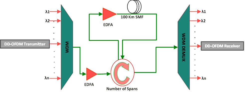
Figure 1. DDO-OFDM-WDM system design.
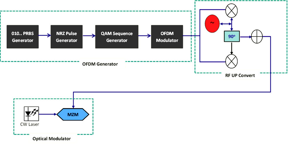
Figure 2. DDO-OFDM transmitter block diagram.
single-mode fiber (SMF) with a wavelength around 1550 nm is used because it offers low attenuation at 0.2 dB. The total bandwidth provided at 1550 nm is approximately 8 THz. The total available bandwidth is divided into various channels, usually with 100 or 50 GHz bandwidth, and is known as dense wavelength-division multiplexing (DWDM). A multi-span of optical fiber consisting of 30-span of 120 Km SMF is used. Also, two erbium doped fiber amplifiers (EDFAs) are used before and after the optical fiber to compensate for the loss in the fiber. After linking the optical fiber transmission, the signal is connected to a WDM demultiplexer to separate the thirty OFDM signals.
2.3. DDO-OFDM Receiver
As shown in Figure 3, the output signal is received from the optical fiber by a PIN photodetector to convert the optical signal to an electrical signal. After that, the OFDM signal is recovered from the RF to a baseband by a Quadrature demodulator and then the signal is transmitted to the O-OFDM demodulator. Finally, a QAM sequence decoder is used to decode the signal and to generate a binary signal. Table 2 shows the O-OFDM demodulator parameter.
The system design is studied and implemented by using a sufficient simulation program called OptiSystem V.11. The global parameter of the system design is shown in Table 3.
3. Dispersion Compensation Fiber (DCF) Design
One of the significant parameters that affect the quality of the signal over long haul transmission link is the dispersion in the fiber. DCF is a highly efficient technique to compensate the chromatic dispersion (CD) in highspeed transmission systems. DCF is designed to achieve a high negative dispersion of up to −80 ps/nm, which can adjust the amount of CD in the optical fiber. The dispersion is broadband, so it has the advantage of adjusting multiple WDM channels at the same time without phase distortion [17].
In this paper, the dispersion postcompensation technique is used to compensate the dispersion and support the system to transmit over 3600 km SMF as shown in Figure 4.
4. Results and Discussion
After simulating the design by using Optisytem, many parameters are considered to measure the system performance.
The constellation shows a two-dimensional scatter diagram of the signal. Figure 5 demonstrates a signal modulated 64-QAM. As can be seen from the graph, all sam-
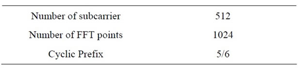
Table 1. OFDM modulator parameters.
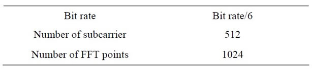
Table 2. OFDM demodulator parameters.
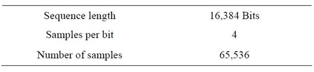
Table 3. Simulation global parameters.
ples are free of interferences and noise.
Figure 6 shows the spectrum of 30 channels of 35 Gb/s each after WDM, with 100 GHz channel spacing. The modulation parameter of each channel has the same settings. The carrier frequencies of the thirty optical signals starting from 193.1 to 196 THz with a spacing of 0.1 THz and each with an average power of 5 mW and linewidth of 1 MHz.
Figure 7 demonstrates the RF signal and it is clear that the signal is free of noise. The carrier frequency of the signal is 7.5 GHz and the power of the RF spectrum is measured at 7 dBm. The OSNR is measured at 59.2 dB and the maximum value of SNR is measured at 102.23 dB by using an electrical carrier analyzer.
Figure 8 shows the RF spectrum of the signal after it transmitted over 3600 km SMF. The OSNR measured at a 43.33 dB. It is clear that the OSNR decreased when the signal was transmitted over 3600 km SMF, due to dispersion and noise.
The parameters of the SMF and DCF are shown in Tables 4, and 5, respectively.
Figure 9 represents the electrical constellation diagram without any dispersion compensation. It is clear that the signal is corrupted and can’t be recognized. The signal is corrupted because of the huge amount of dispersion, noise, attenuation, and interference when the signal travelled over long transmission distance.
To get rid of the high amount of dispersion and recover the original signal, a post-DCF is placed after the SMF to compensate the positive dispersion of the SMF.
Figure 10 illustrates the constellation diagram of the 64-QAM O-OFDM signal at the receiver after DCF is used. As can be seen from the graph, the red points represent the signal and the noise is represented by blue points. Clearly, the signal is recovered after removing the chromatic dispersion from the optical fiber.
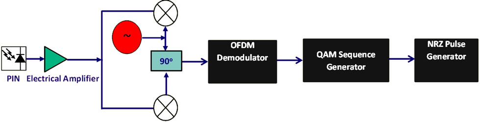
Figure 3. DDO-OFDM receiver block diagram.

Figure 4. Post compensation fiber design.
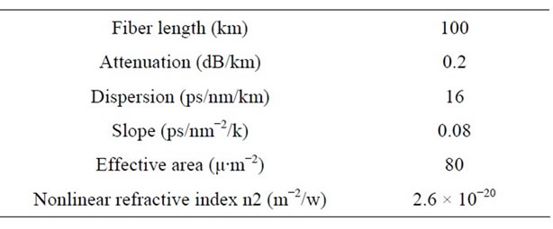
Table 4. SMF parameters.
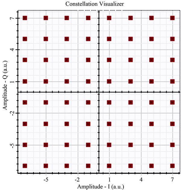
Figure 5. Constellation diagram of 64-QAM at transmitter.
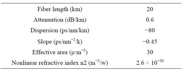
Table 5. SMF parameters.

Figure 6. The spectrum of the signals after WDM.
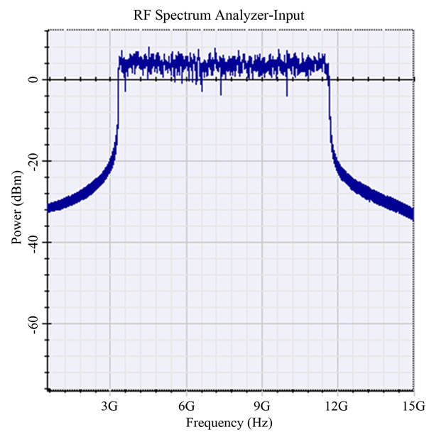
Figure 7. RF spectrum of 64-QAM O-OFDM transmitter for 7.5 GHz carrier frequency.
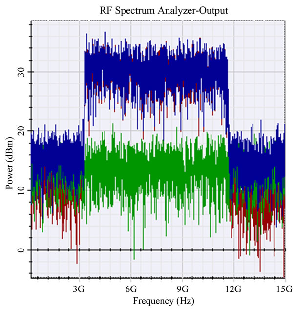
Figure 8. RF spectrum of 64-QAM O-OFDM receiver for 7.5 GHz carrier frequency.
The performance of the system can be studied by measuring the SNR and the OSNR versus BER. Figure 11 shows the BER versus OSNR and it is clear that as OSNR increase the BER decrease. So, to get a BER less than 10−12, the OSNR must be greater than 40 dB.
In Figure 12 the SNR versus BER are plotted where SNR is defined as the ratio of signal power to noise power. It is clear that as the SNR increase the BER decrease. The value of the SNR must be greater than 30 dB
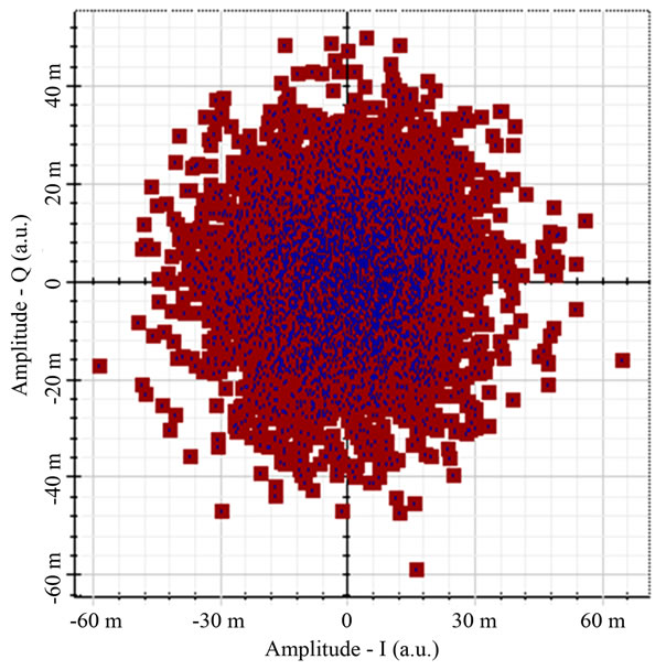
Figure 9. Shows the constellation diagram of the 64-QAM after transmission over 1080 km SMF.
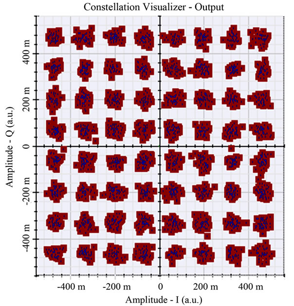
Figure 10. Shows the constellation diagram of the 64-QAM O-OFDM signal after the DCF.
for a BER less than 10−12.
5. Conclusion
In this paper, the combination of DDO-OFDM with WDM was examined and investigated. WDM was used to increase the system capacity and support to reach high data rates of 1.05 Tb/s. 30 OFDM signals of 35 Gb/s were multiplexed to generate a data rate of 1.05 Tb/s. According to the result, the system showed a clear con-
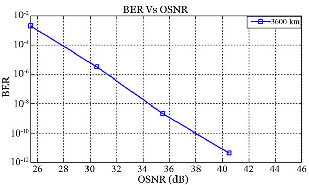
Figure 11. Shows the relationship between BER and OSNR for a transmission length of 3600 km SMF.
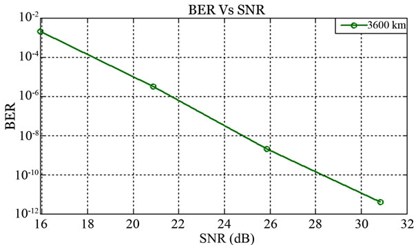
Figure 12. Shows the relationship between BER and SNR for a transmission length of 3600 km SMF.
stellation diagram of 64-QAM at receiver. The results show that the system has a good performance according to the OSNR, SNR, and BER values. The resulting data demonstrated the efficiency of the DDO-OFDM-WDM system in presenting considerably higher data rates.
REFERENCES
- K. H. Liu, B. J. Wilson and J. Y. Wie, “A Management and Visualization Framework for Reconfigurable WDM Optical Networks,” IEEE Network, Vol. 14, No. 6, 2000, pp. 8-15. doi:10.1109/65.885665
- A. K. Dutta, N. K. Dutta and M. Fujiwara, “Optical Packet Switching,” In: A. K. Dutta, N. K. Dutta and M. Fujiwara, Eds., WDM Technologies Optical Networks, Vol. III, Elsevier Academic Press, California, 2004, pp. 119-137.
- C. Chow, C. Yeh, C. Wang, C. Wu, S. Chi and C. Lin, “Study of OFDM Signal for Broadband Optical Access Networks,” IEEE Journal on Selected Areas in Communications, Vol. 28, No. 6, 2010, pp. 800-807. doi:10.1109/JSAC.2010.100805
- W. Shieh and I. Djordjevic, “Orthogonal Frequency Division Multiplexing for Optical Communications,” Elsevier, San Diego, 2010.
- S. D. Dissanayake and J. Armstrong, “Comparison of ACO-OFDM, DCO-OFDM and ADO-OFDM in IM/DD Systems,” IEEE Journal of Lightwave Technology, Vol. 31, No. 7, 2013, pp. 1063-1072.” doi:10.1109/JLT.2013.2241731
- S. Dimitrov and H. Haas, “Information Rate of OFDM Based Optical Wireless Communication Systems with Nonlinear Distortion,” IEEE Journal of Lightwave Technology, Vol. 31, No. 6, 2013, pp. 918-929. doi:10.1109/JLT.2012.2236642
- H. Elgala, R. Mesleh, H. Haas and B. Pricope, “OFDM Visible Light Wireless Communication Based on White LEDs,” Vehicular Technology Conference, Dublin, 22-25 April 2007, pp. 2185-2189.
- S. Dimitrov, S. Sinanovic and H. Haas, “Signal Shaping and Modulation for Optical Wireless Communication,” IEEE Journal of Lightwave Technology, Vol. 30, No. 9, 2012, pp. 1319-1328. doi:10.1109/JLT.2012.2188376
- Y. K. Wong, S. M. Idrus and I. A. Ghani, “Performance Analysis of the OFDM Scheme for Wireless over Fiber Communication Link,” International Journal of Computer Theory and Engineering, Vol. 4, No. 5, 2012, pp. 807-8011. doi:10.7763/IJCTE.2012.V4.583
- W. H. Wen, J. Liu, W. P. Lin and G. Sun, “Millimeterwave Photonic Techniques for Radio-over-Fiber Systems,” Advanced Communication Technology (ICACT), PyeongChang, 19-22 February 2012, pp. 1031-1034.
- L. Mehedy, M. Bakaul, A. Nirmalathas and E. Skafidas, “OFDM versus Single Carrier towards Spectrally Efficient 100 Gb/s Transmission with Direct Detection,” Journal of Optical Communications and Networking, Vol. 4, No. 10, 2012, pp. 779-789. doi:10.1364/JOCN.4.000779
- L. Roselli, V. Borgioni, F. Zepparelli, F. Ambrosi, M. Comez, P. Faccin and A. Casini, “Analog Laser Predistortion for Multiservice Radio-over-Fiber Systems,” IEEE Journal of Lightwave Technology, Vol. 21, No. 5, 2003, pp. 1211-1223. doi:10.1109/JLT.2003.810931
- A. Alateeq, K. Alatawi, F. Almasoudi and M. A. Matin, “Design of Broadband ROF PON for the Last Mile,” Scientific and Research: Journal of Communications and Network, Vol. 4, No. 4, 2012, pp. 269-277. doi:10.4236/cn.2012.44031
- N. J. Gomes, M. Morant, A. Alphones, B. Cabon, J. E. Mitchell, C. Lethien, M. Csörnyei, A. Stöhr and S. Iezekiel, “Radio-over-Fiber Transport for the Support of Wireless Broadband Services,” Journal of Optical Networking, Vol. 8, No. 2, 2009, pp. 156-178. doi:10.1364/JON.8.000156
- OptiSystem Component Library Guide, “Optical Communication System Design Software,” Optiwave Company, Ottawa, 2009, pp. 1375-1420.
- M. Alnoor, “Green Radio Communication Networks Applying Radio-over-Fiber Technology for Wireless Access,” Ph.D. Dissertation, Middlesex University, Middlesex, 2011.
- R. J. Nuyts, Y. K. Park and P. Gallion, “Dispersion Equalization of a 10 Gb/s Repeatered Transmission System Using Dispersion Compensating Fibers,” IEEE Journal of Lightwave Technology, Vol. 15, No. 1, 1997, pp. 31-42. doi:10.1109/50.552111