Optics and Photonics Journal
Vol.2 No.2(2012), Article ID:20399,13 pages DOI:10.4236/opj.2012.22012
A Magnetically Levitated Precise Pointing Mechanism for Application to Optical Communication Terminals
Surrey Space Centre, University of Surrey, Guildford, UK
Email: T.E.Frame@surrey.ac.uk
Received February 9, 2012; revised March 15, 2012; accepted April 21, 2012
Keywords: Optical Communications; Magnetic Levitation; Control; Pointing; Active Anti-Vibration
ABSTRACT
Increasing data bandwidth requirements from spacecraft systems is beginning to pressure existing microwave communications systems. Free-Space optical communications allows for larger bandwidths for lower relative power consumption, smaller size and weight when compared to the microwave equivalent. However optical communication does have a formidable challenge that needs to be overcome before the advantages of the technology can be fully utilized. In order for the communication to be successful the transmitter and receiver terminals need to be pointed with a high accuracy (generally in the order of ≤10 µradians) for the duration of communication. In this paper we present a new concept for the precise pointing of optical communications terminals (termed the Precise Pointing Mechanism). In this new concept we combine the separate pointing mechanisms of a conventional optical terminal into a single mechanism, reducing the complexity and cost of the optical bench. This is achieved by electromagnetically actuating the whole telescope assembly in 6 degrees-of-freedom with an angular resolution of less than ±3 µradians within a 10 (Az. El.) field of view and linear resolution of ±2 µm. This paper presents the new pointing mechanism and discusses the modelling, simulation and experimental work undertaken using the bespoke engineering model developed.
1. Introduction
Communication is an ever growing and advancing field that is driven by many factors. As space borne instrumentation and data gathering/processing systems advance, an inherent increase in the data rate and bandwidth of the communications system follows. Optical terminals can provide advantages such as larger data bandwidths, lower relative power consumption, and smaller size/weight over microwave systems due to the nature of the medium used [1]. Also as the RF communication frequency spectrum becomes more crowded an optical link can offer an attractive alternative without the need for introduction of complex channel filters and algorithms [2] along with a greater immunity and security. However due to the narrow divergence of the medium used in optical communications, a very accurate and responsive pointing system is required in order to maintain the link between the communication terminals. A pointing error greater than a few micro radians can dramatically reduce the power seen on the receiver. Therefore a stable and precise pointing mechanism is required for the duration of communications.
Generally optical terminals consist of a fixed Telescope acting as the antenna, and a series of mirror/optics assemblies (the Coarse Pointing Assembly (CPA), Fine Pointing Assembly (FPA) and the Point Ahead Assembly (PAA)).
The CPA traditionally consists of a gimbal mechanism using stepper motors and gear boxes to achieve movement in azimuth and elevation, such as in the ESA SOUT terminal [3]. An alternative is to use a form of hybrid stepper motor as in the ISLFE optical terminals [3]. The FPA consists of a pair of mirrors that work together to focus the beam onto the receiver unit. In the SOUT terminal the FPA uses a single mirror that is manipulated using a permanently excited DC motor [3]. In the ISLFE terminal however the FPA consists of a single mirror that is connected to Lorentz force actuators that manipulate it using capacitive sensors to control the angular position [4].
Another major requirement of the pointing system is to overcome spacecraft disturbances and maintain the optical link for the duration of communication. Magnetic levitation technology provides a solution to overcoming disturbances, and offers infinite resolution that is only constrained by the sensor resolution and noise. In this research the functionality of the separate pointing mechanisms are combined into a single unit that can reject disturbances shown in [5], [6] and fulfils the requirements of the separate mechanisms [7,8]. This single unit will magnetically levitate and actuate the entire telescope assembly to reduce the number of individual optical elements and reduce complexity of the optical bench.
Magnetic levitation has been considered and implemented in many areas and differing fields, and achieved high precision positioning, as demonstrated by [9] and [10]. However this technology has not been applied to a space-borne magnetically levitated optical telescope. The system developed by [9] levitates a 6-DOF triangular platform that demonstrates a 5 nm position resolution for 6 axes but has a very small travel range in the order of micro-meters. Used effectively this technology can provide the accuracy requirements in order to maintain an effective optical communications link [9,11,12]. Applications of this technology are terrestrial inter building links, space-borne deep space communications, or a GEO-LEO relay satellite in the micro-sat range. The technology presented in this paper could also be adapted to form part of the pointing mechanism of an imaging system where a form of active anti-vibration would be advantageous and improve images [13]. Another application due to recent ESA activity is a direct Earth to Mars link that would significantly improve communications [14].
The purpose of this paper is to introduce the Precise Pointing Mechanism developed here at the Surrey Space Centre. An engineering model that can completely magnetically levitate and actuate a 60 mm telescope antenna in all 6 degrees of freedom has been developed and used to demonstrate the use of magnetic levitation to provide two pointing resolutions (±10 mRadians and ±3 µRadians) for application to an optical communications scenario.
This mechanism is developed to be an enabling technology for use in terrestrial and free-space optical communications, or applications where active anti-vibration and precise pointing would be advantageous. The design is scalable dependent upon the gain requirements of the telescope.
This paper discusses an example application of the engineering model developed, gives an overview of the control strategy used and finally presents some results to demonstrate the resolution of the terminal.
2. Optical Communications Using the PPM
This section presents some applications that can be considered for the engineering model PPM presented in this paper. Using the PPM as the actuation mechanism for optical terminals, it is envisaged that the field of view of the PPM would require that the telescope assembly element be mounted on each spacecraft and Pre-set (As shown in Figure 1) to point in the direction of the next spacecraft to allow communications with the target satellite.
As can be seen from Figure 1 the OCT is not aligned to the spacecraft axis it is aligned to point at the target
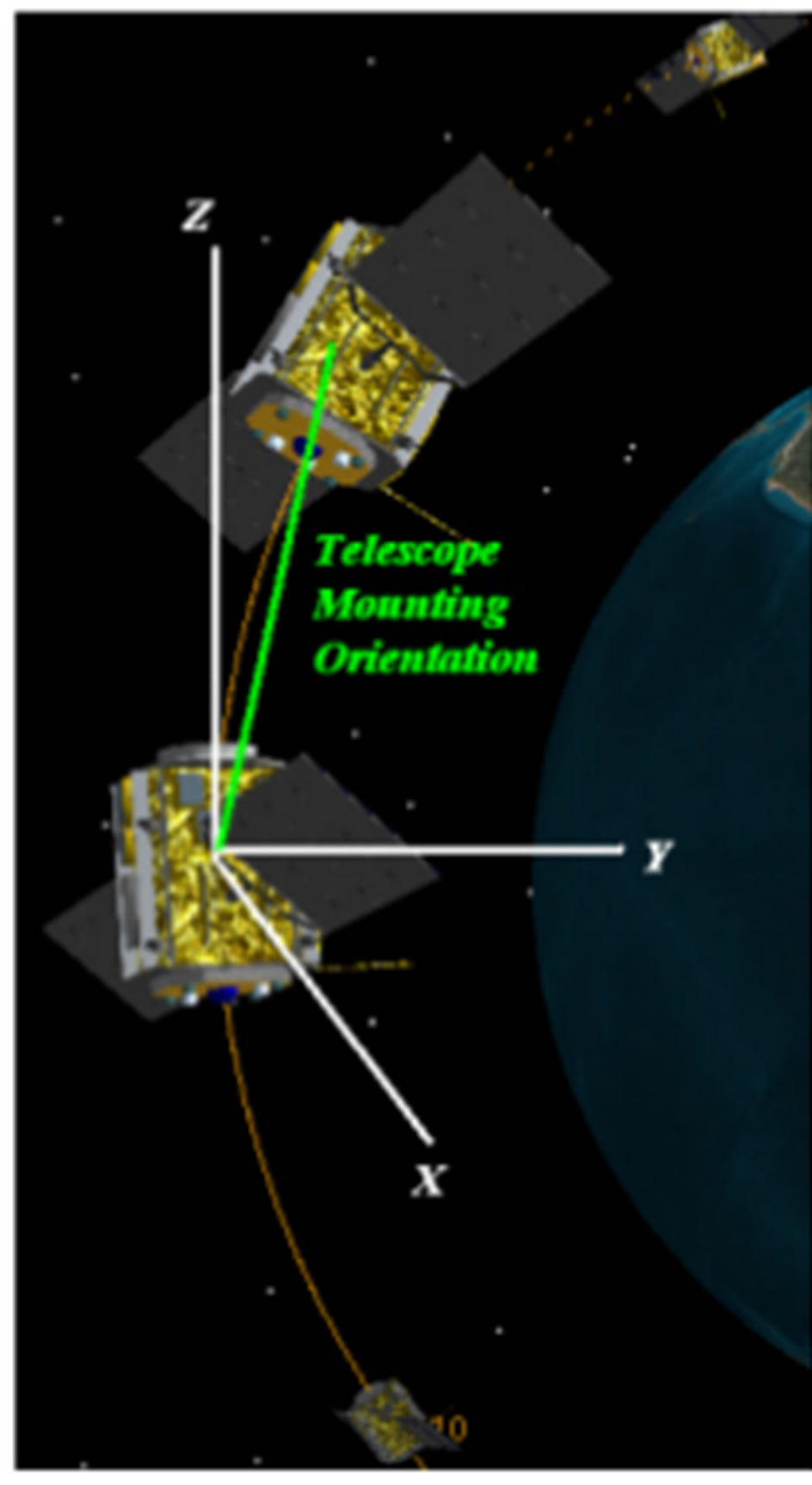
Figure 1. Pre-Set mounting configuration for current T1004- PPM applied to an OCT. Elevation is controlled by the PPM and the Azimuth range is controlled by the slip ring on which the PPM is mounted.
spacecraft. This mounting should be configured so that it is aligned to compensate for the separation of the spacecraft at a pre-defined altitude. Assuming an orbit with an eccentricity of 0.001 (near circular) an assumption for height variations between the two spacecraft is made at ±10 km. If the link distance is in the region of 1000 km then 8% of the terminals azimuth and elevation range is used to compensate for altitude errors. Assuming that the typical attitude error is 1˚, the ±5˚ azimuth and elevation range of the terminal of the engineering model in this research will be able to adequately compensate for altitude and attitude errors of the two spacecraft. If the link distance reduces to 200 km then the pointing requirement for the terminal changes to 77% of the ±5˚ limit of the engineering model.
Considering a GEO satellite to LEO satellite link the usefulness of the PPM can be demonstrated. The GEO satellite has a single PPM terminal mounted on a slip ring on the satellite that allows communication with the LEO satellite. A LEO satellite that has the same orbit properties as the UK-DMC also has a single PPM mounted on a slip ring on it to facilitate communication with the GEO satellite.
The PPM on the GEO satellite is mounted on the Earth facing side of the spacecraft and has a Field of View (FOV) of ±5˚. It has an increased azimuth range of 280˚ due to mounting on a slip ring. By modelling this scenario in AGI’s Satellite Tool Kit (STK) the access between the two satellites can be determined.
The actuation that is required from the terminal is shown in Figure 2. This shows the range through which the PPM terminal has to actuate in order to achieve the
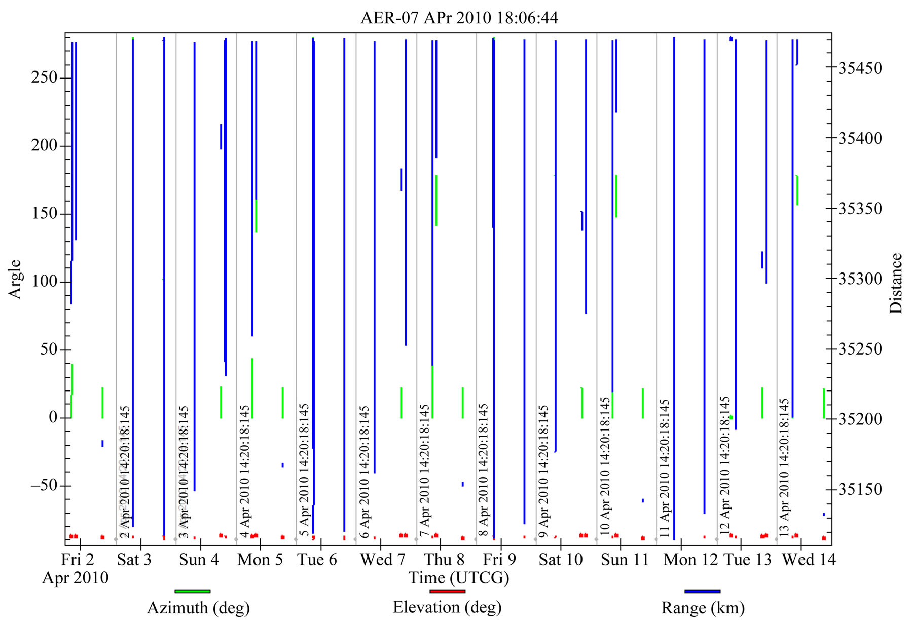
Figure 2. Azimuth and Elevation range for access between UK-DMC and a GEO relay sat. The azimuth range (green) is actuated by the slip ring on which the PPM is mounted. The Elevation (red) is actuated by the PPM and the change in link distance is shown in blue.
access between the GEO and LEO satellites.
The total access for the two week period is 80.82 minutes, at 1 Gbit/s this converts to a total of 4849 Gbit of data transferred. This limited Azimuth and Elevation range is a limitation of the engineering model and not the technology. Future work is considering increasing this range to ±10˚.
3. The Precise Pointing Mechanism (PPM)
This research differs from existing Optical Communications Terminals (OCT) by magnetically levitating the entire telescope assembly of the OCT using a combination of reluctance force electromagnets and permanent magnets. The telescope element is then actuated in 6 degrees of freedom using the electromagnets to compensate for optical pointing errors, thus maximizing received power on an Avalanche Photo Diode (APD). For this evaluation model the pointing controller can compensate for pointing errors within a 10˚ FOV. By actuating the telescope of the OCT the complexity and number of optical components required in the optical bench is reduced. This has the effect of reducing the cost and complexity of the optical bench. A trade off is an increase in power consumption, but this is offset by a saving in mass.
The antenna of this optical communications system consists of a telescope providing a gain to overcome transmission losses and maximize the amount of optical power received from the transmitted source, and thus maximizing the signal to noise ratio and reducing the probability of a bit error rate. OCT applications use reflecting telescopes that utilise the property of paraboloidal mirrors to concentrate and magnify the optical signal. In traditional systems the telescope remains fixed while mirror assemblies are manipulated in order to provide the pointing. This research differs by manipulating the entire telescope assembly in order to fulfill the requirements of the separate mirror assemblies. The operation of the optical system of the PPM is shown diagrammatically in Figure 3.
The type of telescope used in the PPM engineering model will be a Cassegrain configuration. The main driving force for the selection of this type of telescope is the gain and speed achieved from a very small compact terminal (when compared to other types such as Newtonian). A typical Cassegrain configuration consists of two mirrors (a primary parabolic, and a secondary mirror), where the primary has a central aperture drilled that allows the focused light to be reflected through it from the secondary mirror. The focal length of this telescope assembly has been designed to give an F-number of 5 which combines
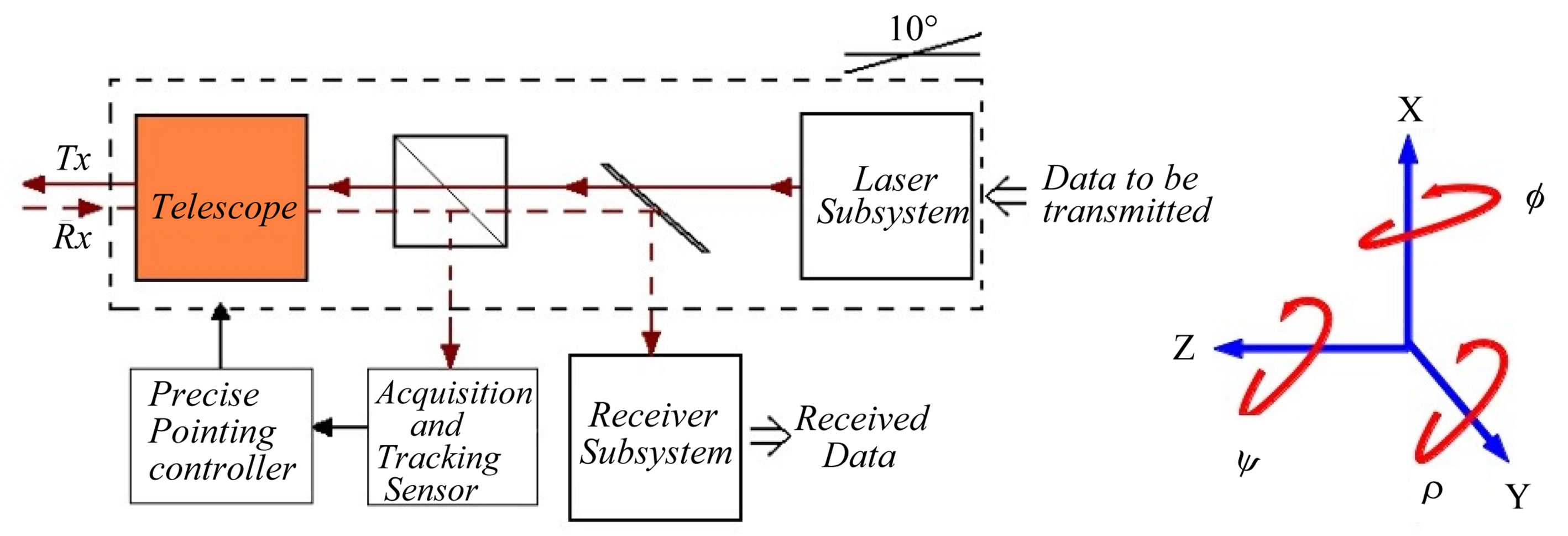
Figure 3. Configuration of OCT using the PPM as the actuation method for the telescope assembly. The optical axis of the telescope assembly is aligned with the Z axis shown.
speed and brightness of image.
3.1. System Configuration
The PPM developed in this research consists of eight reluctance force electromagnets and four pairs of permanent magnets that are used to levitate and actuate the telescope element of the OCT that consists of a catadioptric Schmidt Cassegrain spider configuration. A computer aided design (CAD) image of the evaluation model is shown in Figure 4. The model shown in Figure 4 is only a receiver version of the PPM OCT, but we also have a version that includes a laser transmitter (with some additional optics and different sensor mounting).
The system uses two nested control loops and feedback networks to provide coarse pointing and fine tracking. Coarse pointing is achieved through the use of three low cost Eddy Current Probes (ECP) mounted underneath the telescope assembly (PRS-04 Fabricated by Sensonics). These provide positional data with accuracy around 2 µm which is not adequate to sustain an optical link (as will be discussed later). Fine tracking occurs once an optical signal is present on entrance of the telescope and thus focused onto the Position Sensing Device (PSD), the PDM- 10 produced by On-Trak Photonics. This is a dual axis PSD and tracks the laser beacon to an accuracy of 0.1 µm (±6 µm seen on the active area of the PSD) which can sustain the proposed optical link without excessive degradation of the communication channel. These measured errors in pointing are then used by the controllers to actuate the telescope to reduce the overall pointing error.
The engineering model was fabricated by the workshops of the University of Surrey with some parts. Such as the laminated electromagnet cores being sub contracted. Figure 5 shows the completed PPM setup in the SSC laboratories, mounted on a passive anti-vibration table. This is to reduce the influence of stray vibrations on the PPM during experimentation.
The engineering model was designed to demonstrate the levitation and actuation of the telescope of an OCT using low cost COTS, and to demonstrate the use of layered control loops combining lower resolution sensors and low cost higher resolution sensors, resulting in a range of pointing accuracies required to maintain an optical link.
Although the data rate of the OCT scenario is not evaluated in experimentation the divergence of the link scenario is facilitated using a small lens mounted on the aperture of the laser. This diverges the laser at an angle of approximately 30˚. The entrance pupil to the telescope assembly is then 150 mm away from the laser source which allows the optics (which were designed for a 3000 km optical link) to focus the laser source back to a fine spot on the PSD. It was found during experimentation that the quality of the low cost laser introduced a small positional error caused by the elliptical beam shape at the exit of the laser.
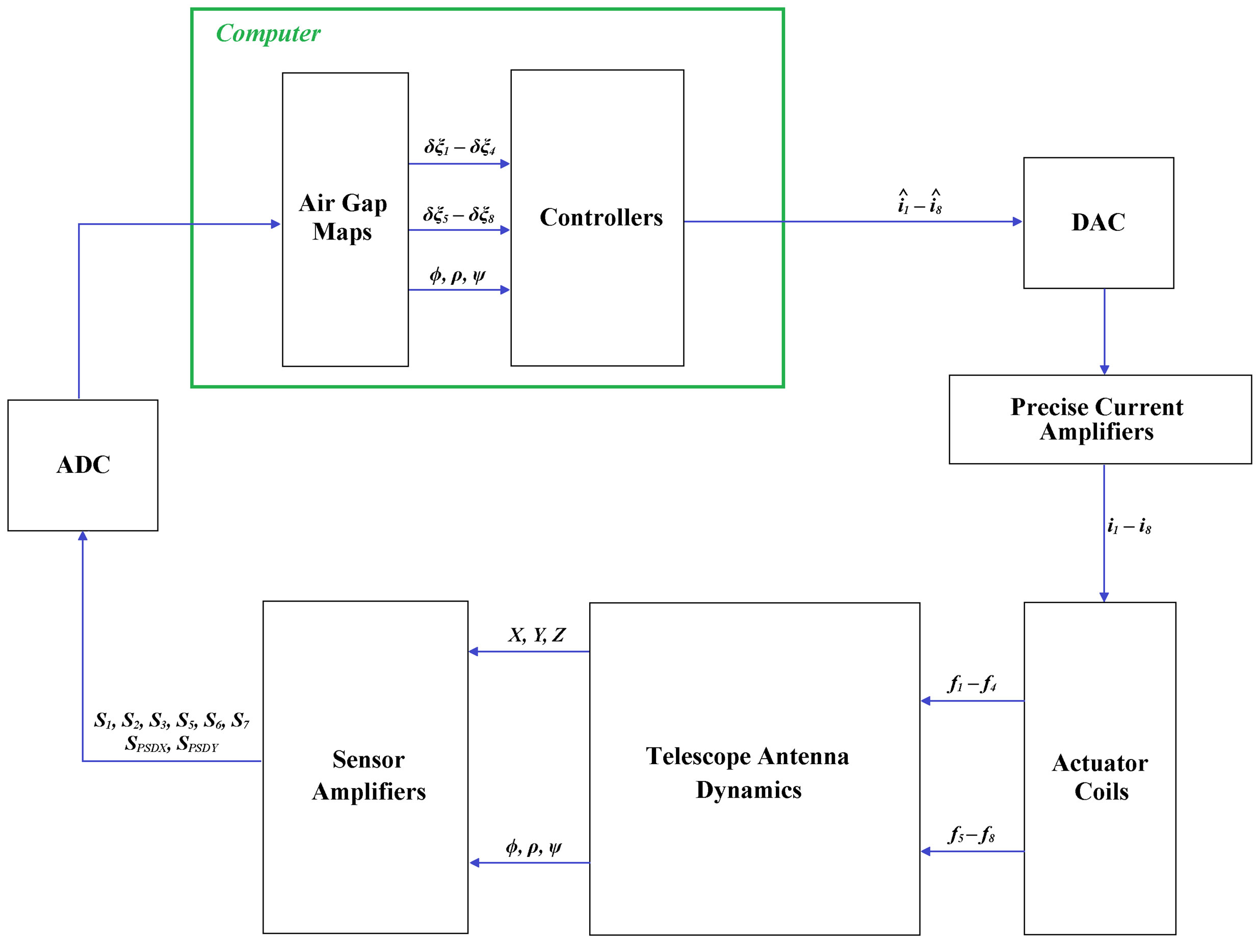
A system diagram that describes the configuration of the PPM experiment is shown in Figure 6.
The PPM OCT is divided into a number of different elements that have been developed to achieve a pointing resolution to sustain a free-space optical communications link.
3.2. System Model
In order to simulate the PPM system a model was developed in Matlab that represents the dynamics of the ter minal and the hardware from which the engineering model is constructed. Figure 6 shows the system diagram that contains models of the Telescope Antenna dynamics, Sensor Amplifiers, Actuator Coils and Current Amplifier models in order to generate an accurate system model for development of the control system. This model was implemented in the Simulink environment of Matlab and used to simulate performance of the PPM before implementation on the bespoke hardware. The model initially included linearised models of the electromagnetic cores in order to allow the development of the control system. Once this was completed and demonstrated in simulation the model for the electromagnetic actuators was replaced with its non-linear version to model the real life behavior of the actuators within the system. Experimentation was also undertaken to ascertain the resolution
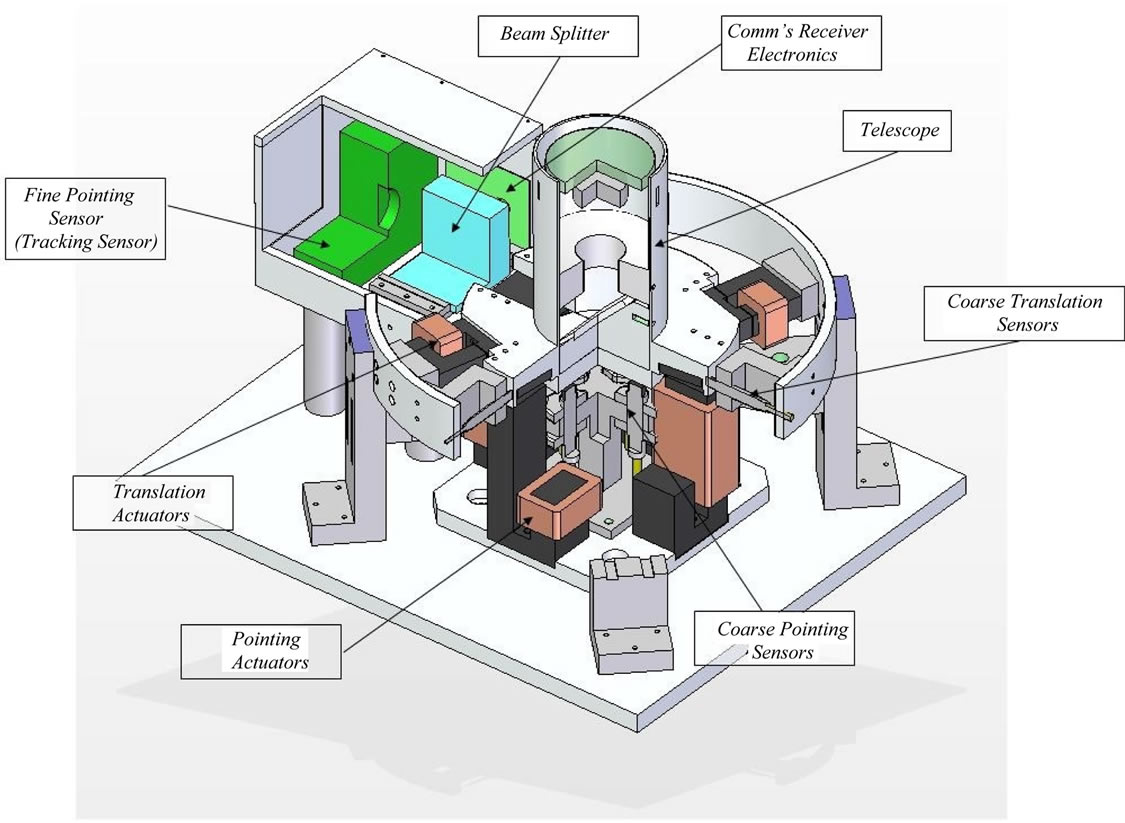
Figure 4. CAD image showing layout and elements of the PPM.
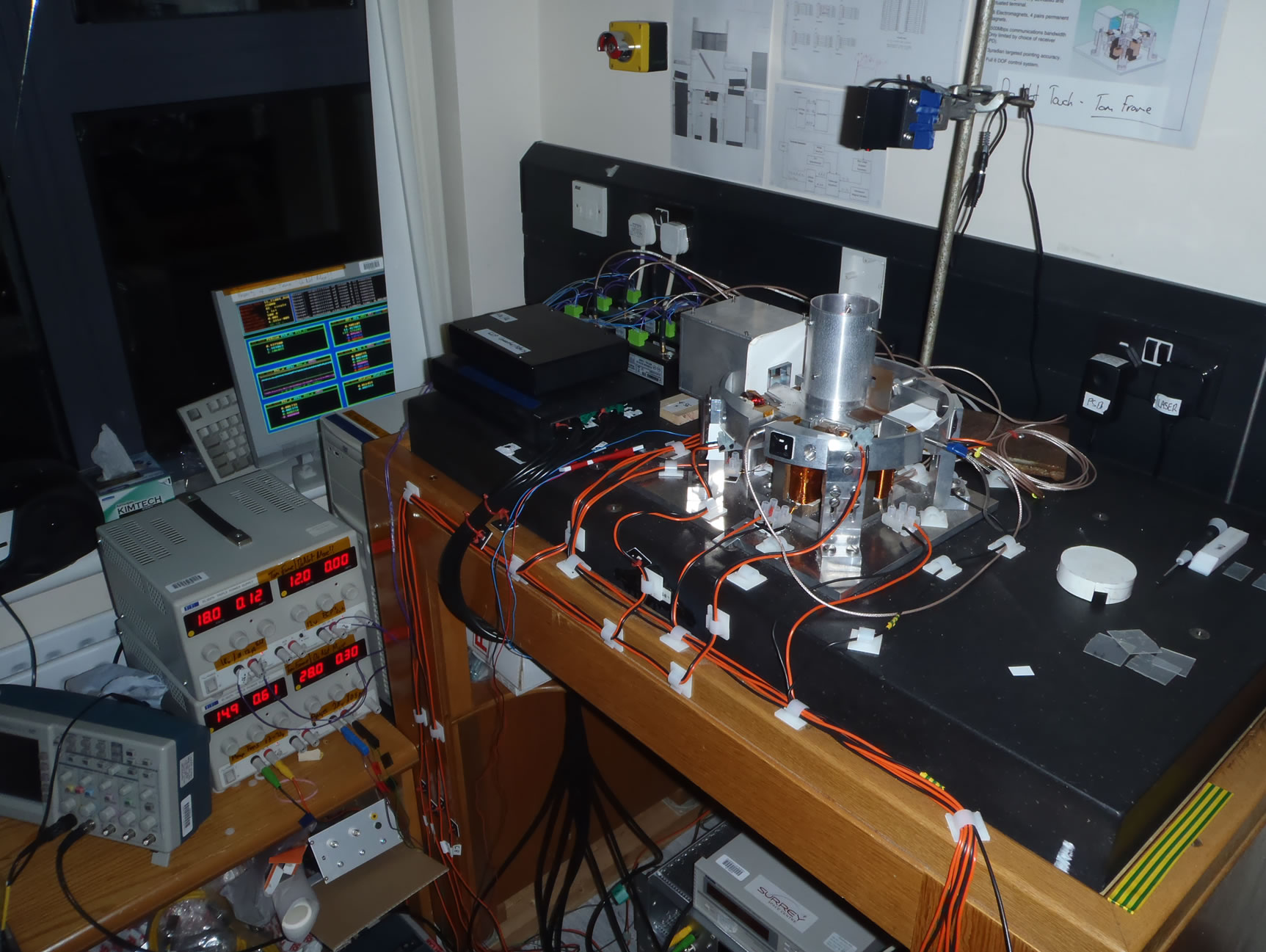
Figure 5. Implemented PPM mounted on anti vibration table.
of the ECP’s and fine tracking sensor so that they could be modeled as accurately as possible. Finally noise from the bespoke precise current amplifiers that drive the current in each actuator was found experimentally for each actuator channel and then modeled for completeness.
In hardware all but the “Computer” elements (shown in the green box) are replaced with their hardware equivalents. National Instruments 6023E Analogue to Digital Converter (ADC) card and 6703 Digital to Analogue Converter (DAC) card are used as the interface components between the PPM hardware, and the host computer running XPC real time environment on which the control system is implemented.
Telescope Assembly Dynamics
The configuration of the Telescope Antenna of the PPM contains both translation and rotation components.
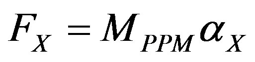
The behaviour of the PPM in translation along the X, Y, or Z axis is governed by Newton’s Second Law as in Equation (1),
 (1)
(1)
where FX is the force acting along the X axis, MPPM is the mass of the telescope assembly and αX is the acceleration along the X axis. The accelerations (αX, αY and αZ) are found in the PPM by taking the second derivative of the terminal displacement along each respective axis, which is measured through the use of the coarse sensors (ECP’s).
The Telescope Assembly (shown in Figure 7) is designed so that Centre of Mass (CM) is also the centre through which the Telescope Assembly rotates. This location is shown in Figure 7, and occurs in the centre of the 45˚ mirror that is used to divert the focused laser spot onto the fine tracking sensor. This reduces the complexity in the control and reduces the amount of power needed to rotate the telescope. If the CM of the Telescope Assembly was located at the entrance pupil more power would be needed in the actuators to maintain stability of the system.
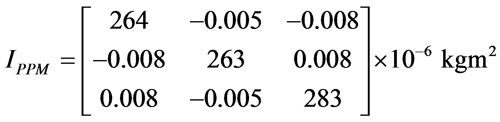
The Inertia of the telescope assembly shown in Figure 7 can be described as Equation (2).
 (2)
(2)
These align with the X, Y and Z axis of the telescope assembly. Using Equation (2) in Euler’s equation of motion to describe the rotational motion of the telescope assembly, we yield Equation (3).
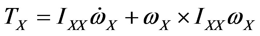 (3)
(3)
where the torque about the X axis is given by TX, (and similarly for the Y and Z axis, TY and TZ respectively), ωX is the angular acceleration about the X axis.
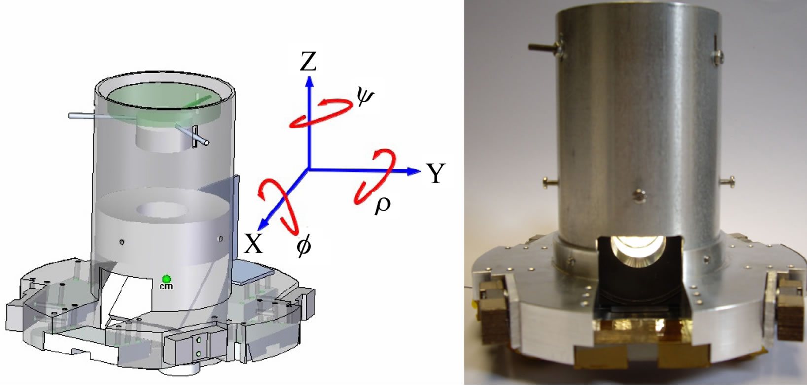
Figure 7. Illustration showing the location of the Centre of Mass of the Telescope Assembly (left), and a photo of the fabricated Telescope Assembly for use in the engineering model (right).
3.3. Optical Bench
This part considers the simulation of the antenna element of the OCT and considers some sources of error that will affect the performance of it, which will impact the fine pointing resolution of the PPM. An F5 catadioptric Cassegrain telescope has been developed as this offers a good compromise between image intensity at the focal plane and speed. A note to consider is that this Telescope Assembly would need to be used at least 15˚ off the sun-line in order to prevent damage to the receiver and optics. This requirement can be modified by developing baffles. The 60 mm diameter parabolic mirror and telescope aperture gives a gain of approximately 106 db generated by the telescope to offset some of the losses associated with free space optical communications.
The telescope assembly is tilted about φ and ρ (X and Y shown in Figure 7 to correct for pointing errors, while the remaining four degrees of freedom remain fixed (X, Y, Z and rotation about Z, ψ).
Figure 8 shows the ray trace for the engineering model with a zero degree pointing error in the incoming rays. The laser source is modelled as a Laser Diode placed 150 mm away from the entrance to the telescope with a 30˚ divergence angle. This is representative of the engineering model configuration and the divergence angle of the laser is achieved through the use of a diffusing lens mounted at the exit of the laser source.
In Figure 9 the incoming rays from the laser source are focused onto the centre of the Tracking Sensor and APD (via the beam splitter hard mounted onto the stator element of the terminal). The radius of the focused laser signal spot is approximately 2 microns RMS seen on both the centre of the Tracking Sensor and the APD. An image of the spot using relative intensity values can be seen in Figure 9. The relative illumination on the fine tracking sensor and the spot position can be seen in Figures 10 and 11 respectively.
3.4. Magnetic Actuators
The PPM consists of two electromagnetic systems that provide levitation and control over the pointing and
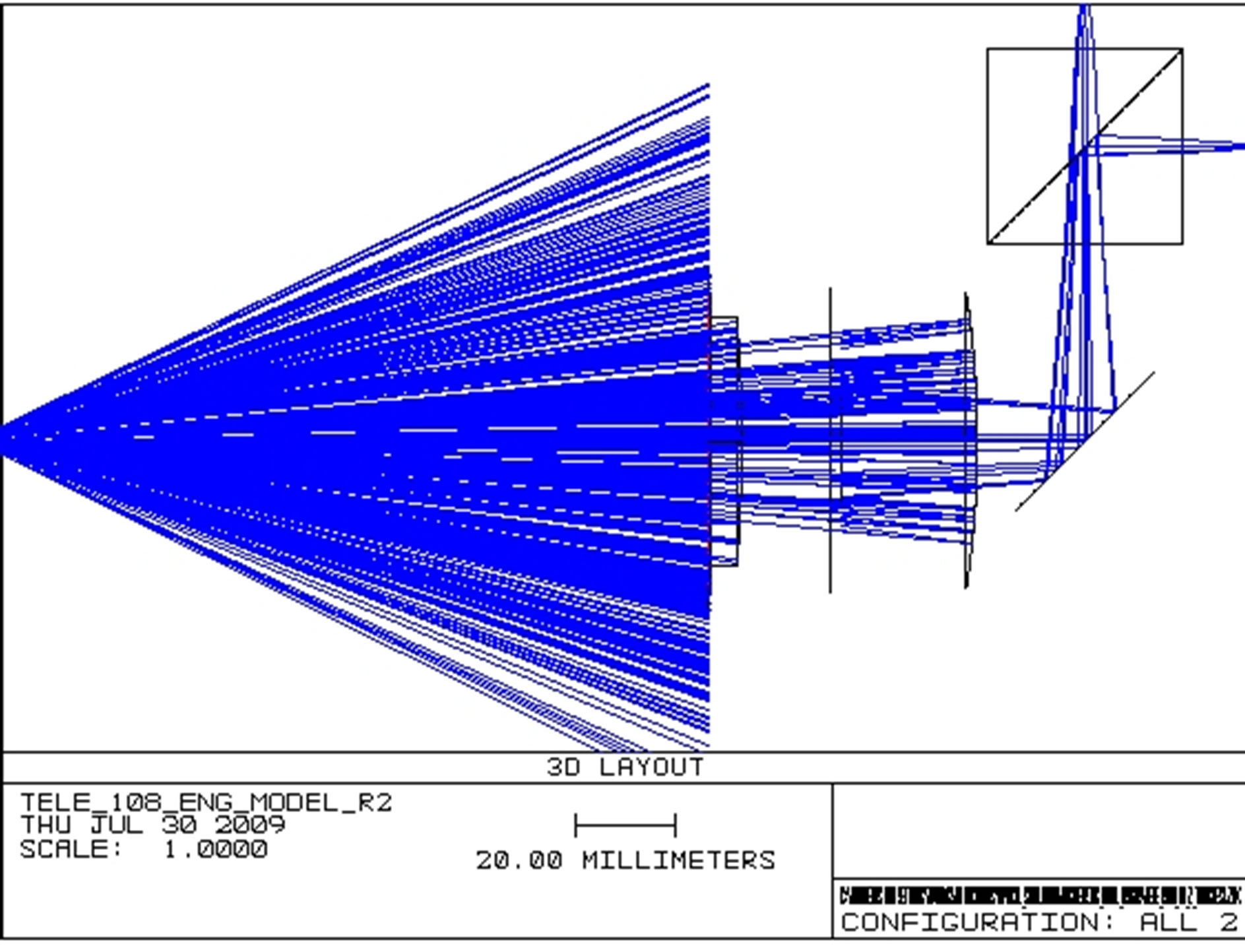
Figure 8. Ray trace image of terminal with 0º pointing error.
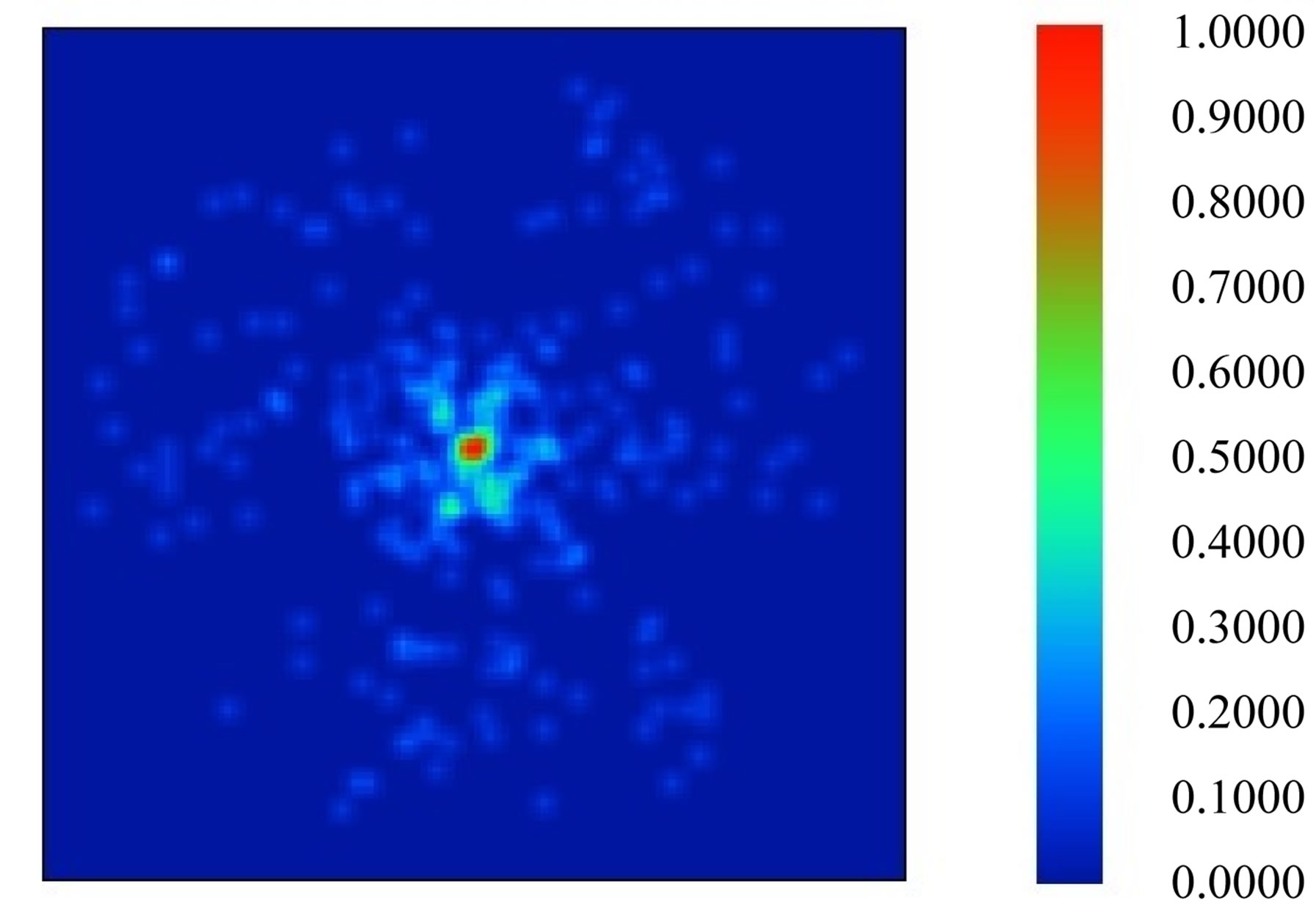
Figure 9. Relative intensity spot image on the tracking sensor with a 0º pointing error. This slide is 10 µm square at a resolution of 128 by 128 pixels.
translation of the telescope antenna in 6 Degrees of Freedom (X, Y, Z, φ, ρ and ψ). Two sets of electromagnetic cores were designed and manufactured by Photofabrication.
The magnetic systems are illustrated graphically in Figure 12.
The actuators highlighted in blue control translation along Z, rotation about X (φ) and rotation about Y (ρ). The actuators highlighted in green control translations along X and Y and rotation about Z (ψ).
Pointing in this context refers to φ, ρ and ψ, and translation refers to linear motion along axis X, Y and Z.
Permanent magnets (PM’s) are used in a repulsive configuration that have been sized and selected in order to provide a levitation force along the Z axis (Figure 14) are shown in Figure 13. The repulsive force generated by these permanent magnet pairs serves two purposes. For Earth testing of the PPM this force offsets the effects of gravity on the mass of the telescope antenna. It also provides a force that opposes the reluctance force generated
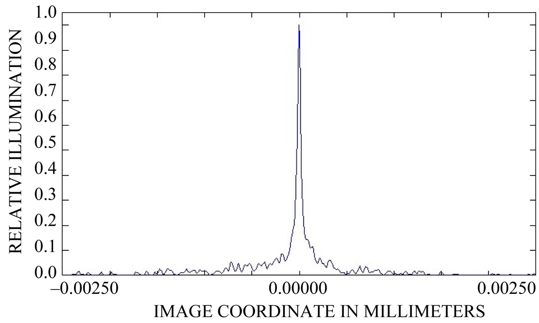
Figure 10. 2D relative intensity on the X axis of the tracking sensor with 0º pointing error.
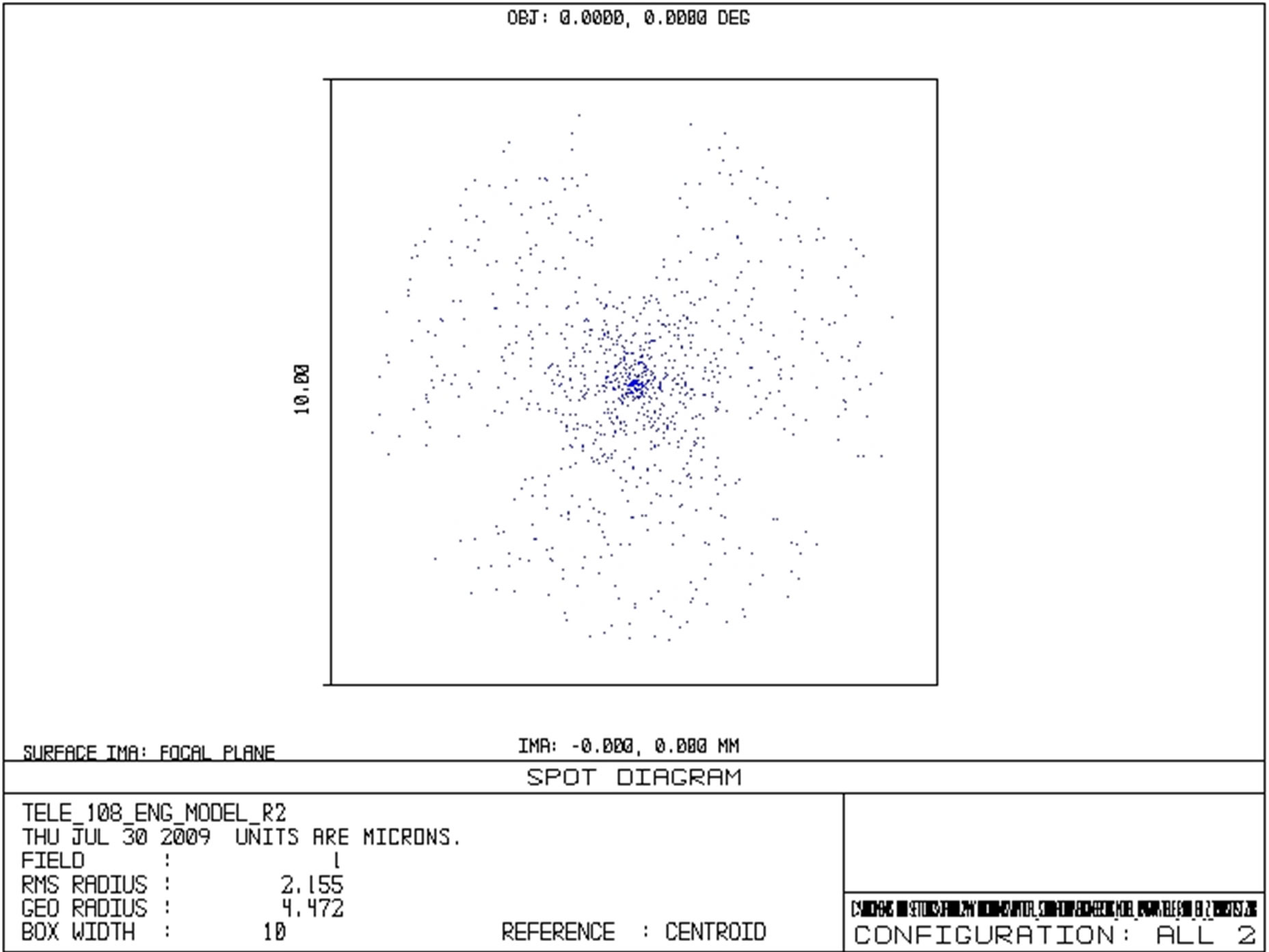
Figure 11. Spot size and position on the active area of the tracking sensor with 0º pointing error.
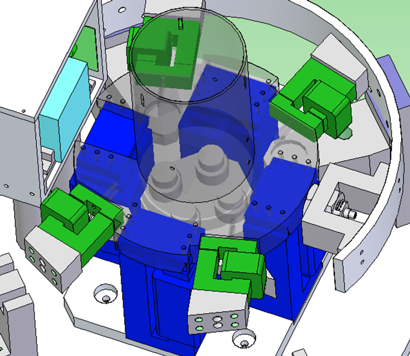
Figure 12. Illustration showing the magnetic systems that levitate and actuate the PPM.
by the four electromagnets, thus allowing control over the Z displacement. The forces produced by the pointing actuators for this engineering model total a net force of 12.04 N.
The force allows the effects of gravity on the telescope assembly to be offset, as well as providing a net force of approximately 0.04 N (in reference position) for the pointing actuators (f1, f2, f3 and f4) to overcome, allowing
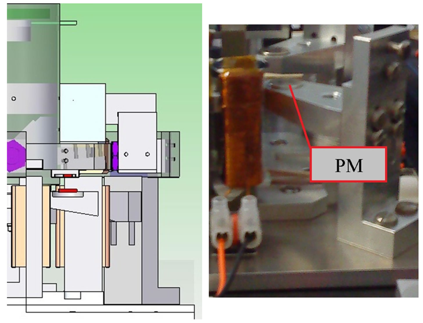
Figure 13. CAD image showing position of the permanent magnets highlighted in red (left) with a photo showing the position of the lower permanent magnet within the PPM. The top PM is embedded in the telescope assembly (right).
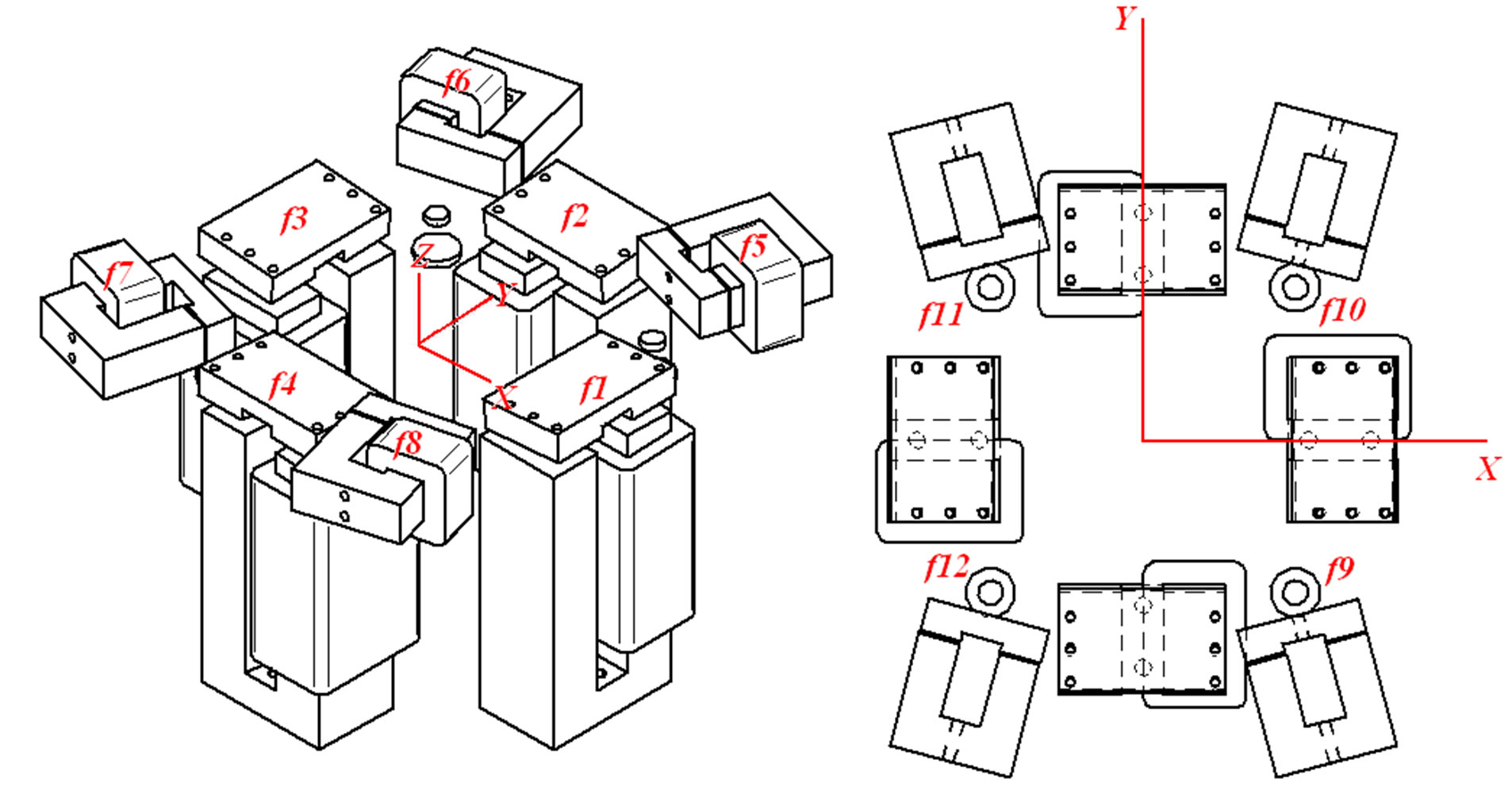
Figure 14. Layout showing placement of electromagnets and forces.
levitation to be achieved.
The repulsive forces produced by the permanent magnets is a function of the air gap between the pairs, therefore this is adjustable in order to allow these forces to be tuned on the engineering model.
The permanent magnets also produce undesired forces that induce a torque (TZ) about the Z axis, and unwanted translation along X and Y.
The effects of these are reduced as much as possible through offsetting the positions of the permanent magnets. Through magnetic modelling using the Ansoft Maxwell 3D package the unwanted forces generated were found to be less than 10% of the force produced by the electromagnets when a full 5˚ (scenario in which worse case unwanted disturbances are experienced), rotation about φ and ρ was commanded, so there is adequate margin in the electromagnets to overcome these disturbances.
3.5. Control System
The control architecture of the PPM consists of six Single Input Single Output (SISO) decoupled controllers that each controls a single degree of freedom utilising a coarse sensor network that comprises Sensonics PRS04 and PRS02 Eddy Current Probes.
A further two controllers are then implemented using a fine tracking sensor that consists of the On-Trak PSM-10 position sensing device (PSD). This control strategy is summarised in Figure 15.
It is this combination that allows for the two resolutions achievable using the PPM (Coarse and Fine). The telescope assembly is actuated by manipulating the magnetic field in order to change the displacement of the telescope assembly.
In essence it obeys the relationship of Equation (4), where FX is the force along the X axis, fbias is the bias force applied to that actuator and δ is the demanded force from the control system to correct for disturbances on the telescope assembly.
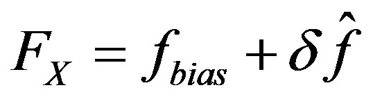 (4)
(4)
Using the relationship between the force produced by the actuators and the current required to generate that force (Equation (5)) together with the inverse of the terminal dynamics the change in each individual actuator fn,
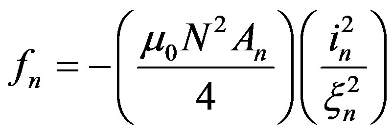 (5)
(5)
where in is the current in the nth coil and ξn is the air gap between the rotor and core parts (the rotor being attached to the telescope ring), µ0 is the permeability of free-space, N is the number of turns of conductor on the electromagnets core and An is the area of a single actuator pole face. The force generated by the electromagnets is a reluctance force which is always attractive therefore the minus sign in Equation (5) represents this attraction.
The current demands from each controller are then mapped onto the required electromagnetic cores to generate these desired force changes to correct for disturbances and pointing errors influencing the telescope assembly. The controllers are implemented in the form of Lead-Lag compensator’s in the form of Equation (6).
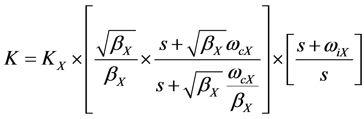 (6)
(6)
where KX is a gain term for the axis in question, βX is the damping coefficient and ωcX and ωiX are the corner frequencies of the lead and lag terms respectively. The gain term KX was derived from the dynamic model for the telescope assembly when the gain of the controllers causes the magnitude to be 1 at the cross-over frequency. The gains are then tuned once when implemented in simulation or on the hardware. When implementing the control strategy on the simulation model or hardware the controllers did not initially include an integration term (the lag term in the controller), which was added once the
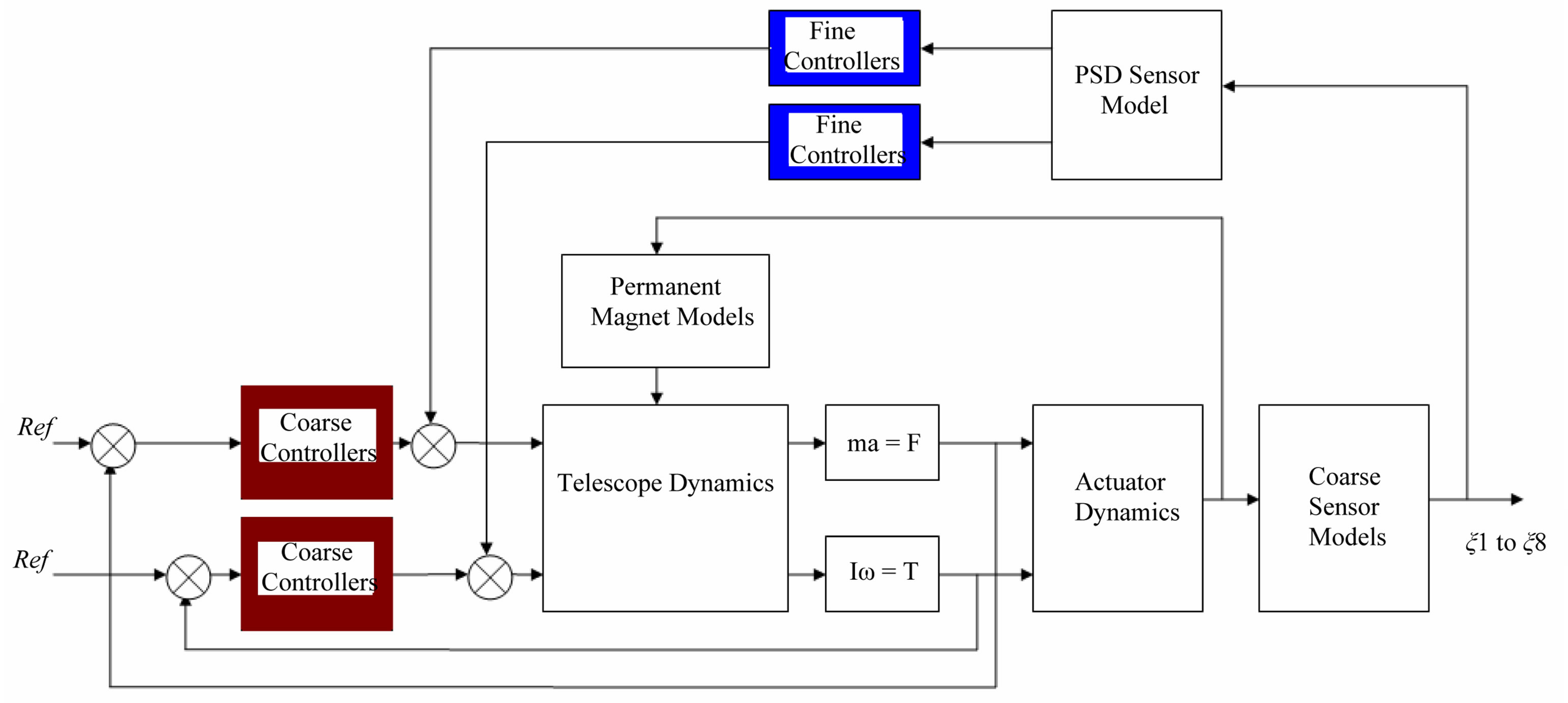
Figure 15. Overview of control strategy to levitate and track an optical signal. In red are the coarse controllers that levitate and actuate the telescope assembly using the eddy current probes, and in blue are the fine controllers that tilt the telescope about X and Y (φ and ρ).
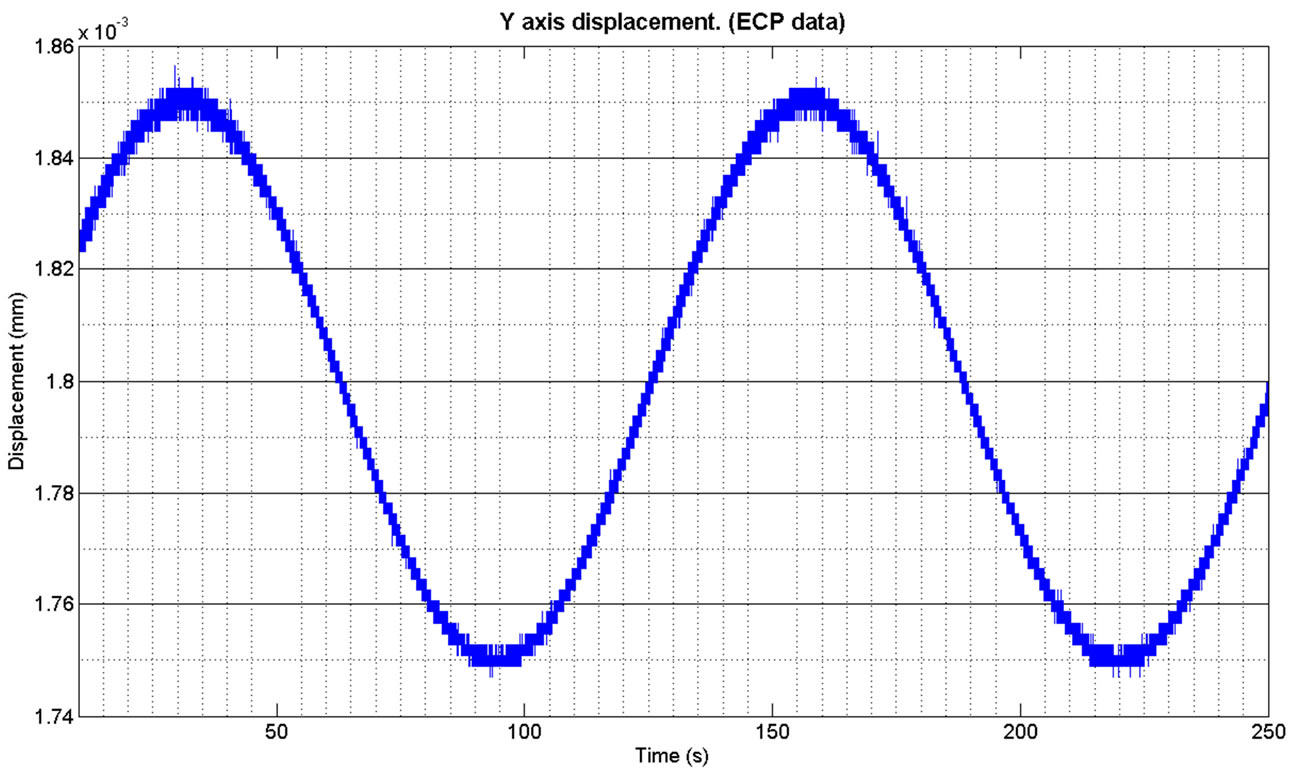
Figure 16. Response of the Y axis (S6 ECP data) to a sine wave using the coarse control loops and sensor network.
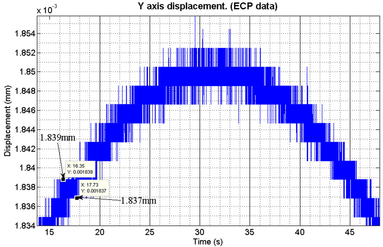
Figure 17. Zoomed in top section of Y axis response. The quantisation noise can clearly be seen and the positional resolution of the axis is ±2 µm.
system was stabilised. This made it easier to achieve levitation and actuation, although as expected the steadystate error was quite high for each axis.
It was at this point that the fine controllers were introduced to the system to provide an extra level of feedback from the fine tracking sensor that manipulates φ and ρ to compensate for pointing errors using the position error of the laser spot on the PSD.
They take the same form as shown in Equation (6), and did not include the lag term initially. A commanded sine wave was used to demonstrate the response of the terminal along the Y axis. The response of the telescope assembly, along with the quantisation noise can be seen in Figures 16 and 17. This also shows the step sizes achievable along this axis.
A commanded rotation for φ was driven with a similar sine wave (±8 milli-radians @ 0.05 rad/s). Rotation φ is driven by a commanded torque TX about the X axis. Figure 18 shows the rotation of the telescope assembly in response to the commanded position changes.
Figure 19 shows the position of the terminal once the Laser is passed through the telescope optics and incident on the active area of the PSD.
Due to the mechanical fixing of the PSD a positive change in angle φ corresponds to a negative peak on the active area of the fine tracking sensor (the PSD). This is illustrated in the time differences in positive peaks in Figures 18 and 20.
The positional resolution of the telescope assembly while under coarse control is within ±5 µradians for both φ and ρ, which is short of the resolution required to maintain an optical communications link.
However during simulation of the engineering model the resolution of the eddy current probes was expected to be lower than the 2 µm (expected to be around ±4 µm) that could be expected under typical operating conditions. This is shown in the histogram of Figure 21.
During implementation the performance of the ECP
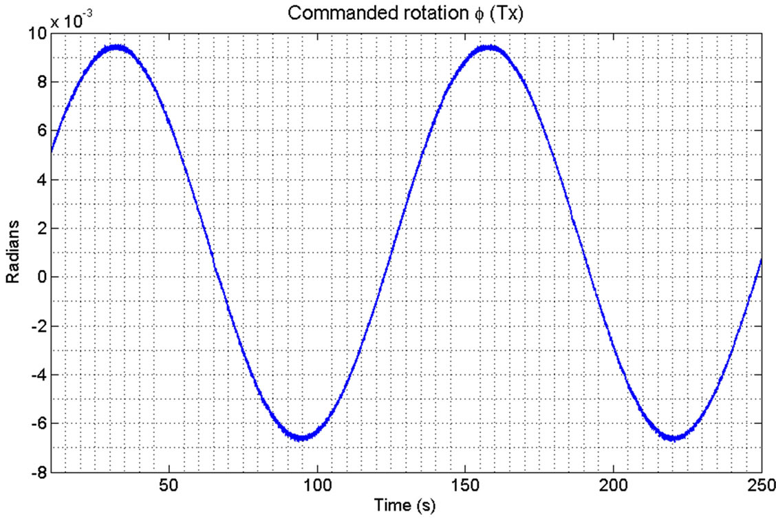
Figure 18. Response of the telescope assembly to a commanded rotation of φ.
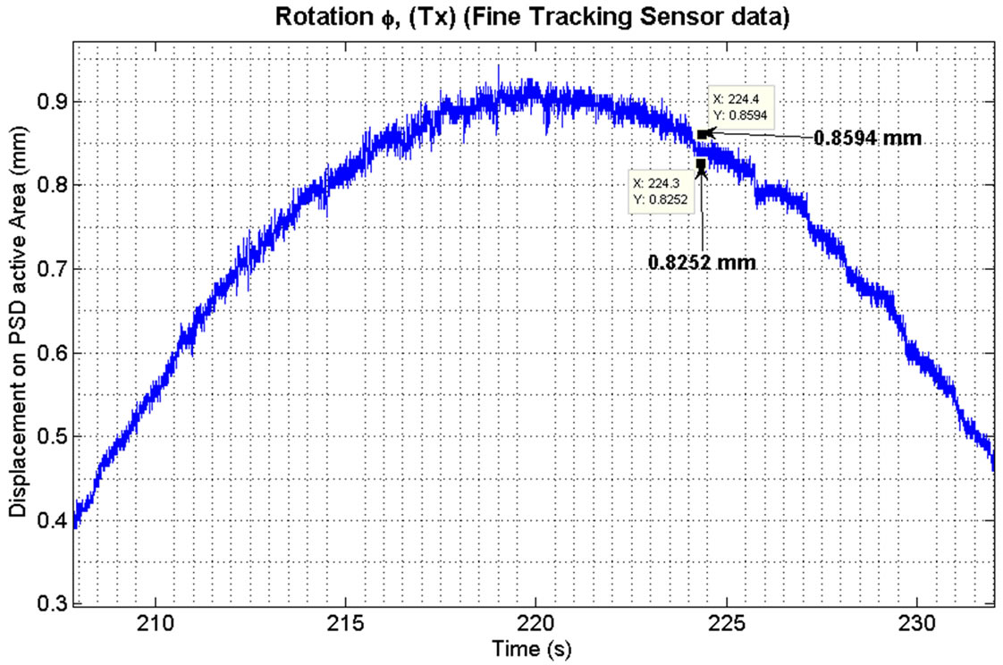
Figure 19. Rotation φ as seen on the respective axis of the fine tracking sensor (PSD). This corresponds to a resolution of approximately 0.18 mRadians under coarse control.
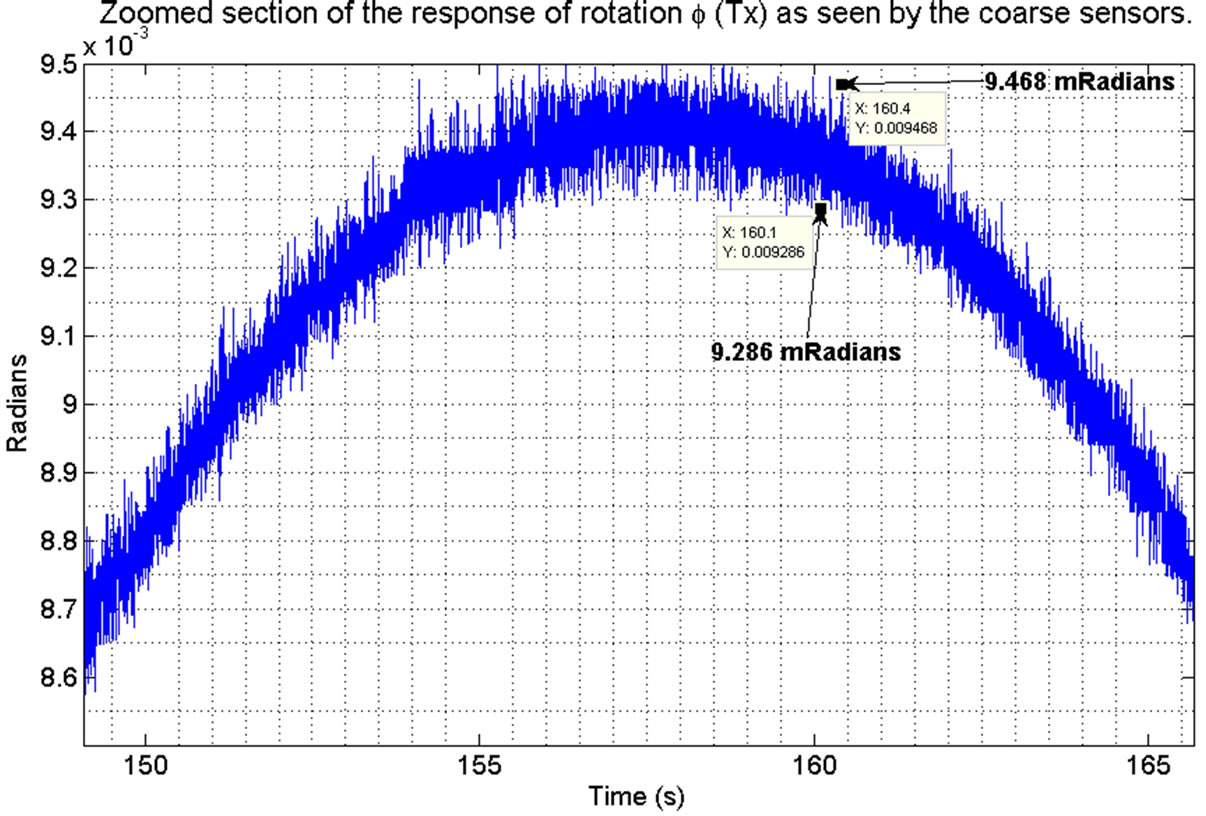
Figure 20. Zoomed view of the response of φ shown in Figure 18. This shows the positional resolution to be approximately 0.18 m Radians.
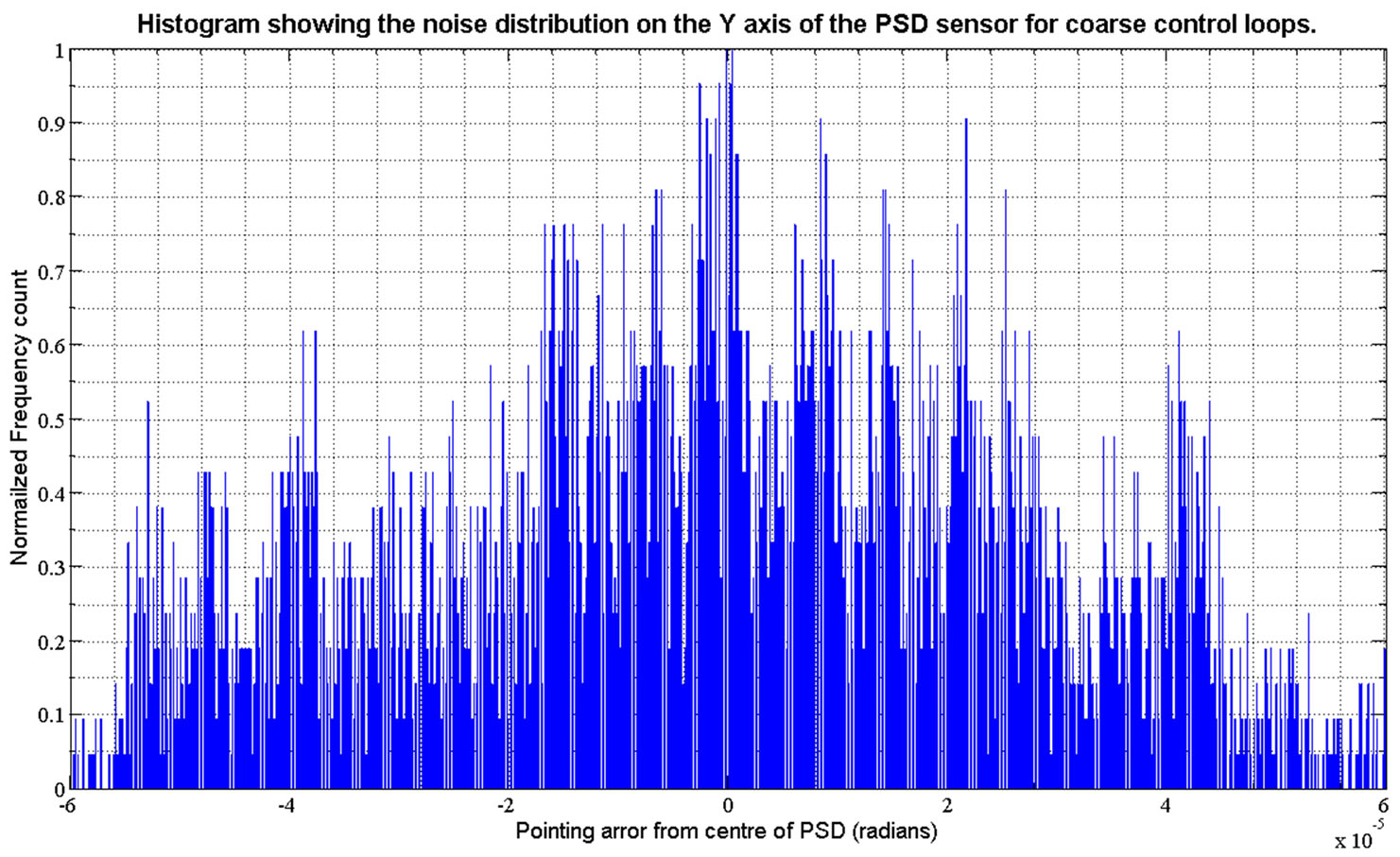
Figure 21. Pointing resolution of the simulated coarse control loops using the ECP sensors.
sensors was worse than modelled in simulation (In the order of ±6 µm. This was due to the metal used in fabrication of the telescope assembly and the small size of sensing area available on the telescope assembly. The performance was dramatically improved however with the addition of very thin steel sheets that were glued to the sensing surfaces of the telescope assembly.
This has the effect of dramatically increasing the conduction of the eddy currents which in turn improves the resolution and performance of the ECP’s.
At this point if an optical signal is incident on the PSD tracking sensor then the fine control loops are activated and the terminal actuated to track the signal.
The resolution of the fine loop is plotted over the top of the coarse control loops to demonstrate the two resolutions achievable with the PPM of this research (Figures 22 and 23).
The histogram is taken over 400 seconds of steady state data. The experiment was repeated a number of times over a large range of pointing positions. The curve shown in black is the modelled pointing resolution requirements for a 3000 km optical link [15].
4. Conclusions
This research has seen the investigation, implementation and successful testing of a new concept for the precise pointing of, in this instance an optical antenna for communications. The realisation of the PPM allows for sub
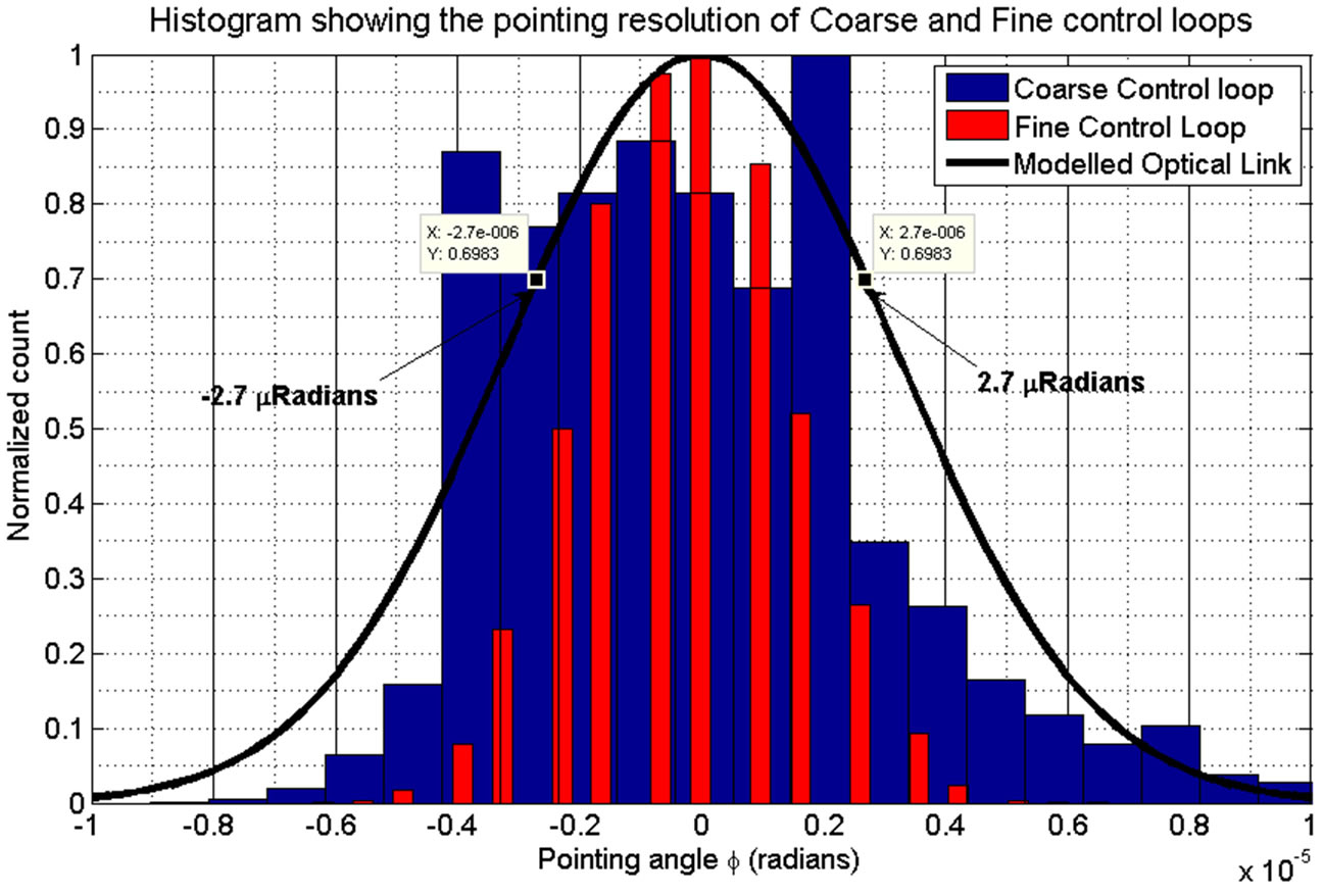
Figure 22. Coarse and fine pointing control loops plotted against the received optical power as a function of pointing angle error for φ.
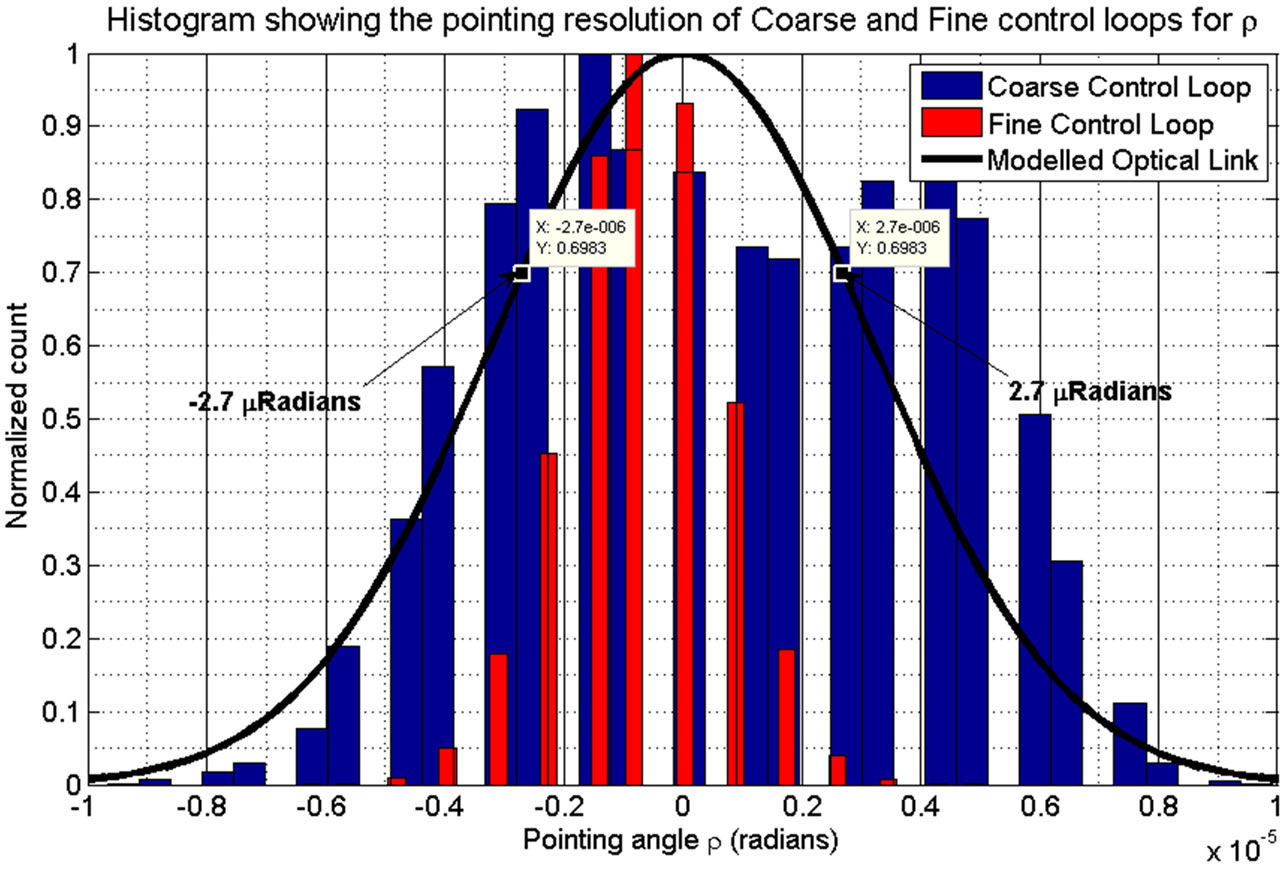
Figure 23. Coarse and fine pointing control loops plotted against the received optical power as a function of pointing angle error for ρ.
micro-meter, and sub micro-radian resolution in all six DOF over a larger displacement range than existing systems. This represents a significant step forward when compared with other mechanisms that utilise magnetic levitation, which, while achieving resolutions comparable to the PPM generally lack the displacement range.
The control strategy presented allows the combination of low cost lower resolution sensors for measuring the position within 6 DOF, with a higher cost greater resolution sensor to achieve an overall increase in accuracy and resolution of the system. This strategy can be utilised to reduce the cost of implementation while retaining the resolution requirements within a system.
The frictionless environment, and contact less nature of the PPM means that the positional accuracy will not degrade as a function of mechanical wear. This also means that no lubrication is required, which can be a significant issue in space craft mechanism. Although the lifetime and consistency of operation cannot be evaluated in the lifetime of this research, no degradation or inconsistency in functionality could be observed during the eight months of experimentation.
5. Acknowledgements
The authors would like to thank The Nuffield Foundation for their support of this project through grant NAL/32791, and ESA for their contribution under a pump priming fund (FRSF09/16).
REFERENCES
- S. Arnon, S. Rotman and N. S. Kopeika, “Optimum Transmitter Optics Aperture for Satellite Optical Communication,” IEEE Transactions on Aerospace and Electronic Systems, Vol. 34, No. 2, 1998, pp. 590-596. doi:10.1109/7.670339
- H. Wang and Q. Chu, “An Inline Coaxial Quasi-Elliptic Filter with Controllable Mixed Electric and Magnetic Coupling,” IEEE Transactions on Microwave Theory and Techniques, Vol. 57, No. 3, 2009, pp. 667-673.
- G. Baister and P. Gatenby, “The SOUT Optical Intersatellite Communication Terminal,” IEEE Proceedings Optoelectronics, Vol. 141, No. 6, 1994, pp. 345-355.
- G. Baister and C. Haupt, “The ISLFE Terminal Development Project Results from the Engineering Breadboard Phase”, 20th AIAA International Communication Satellite Systems Conference, 12-15 May 2002.
- M. Toyoshima and K. Araki, “In-Orbit Measurements of Short Term Attitude and Vibrational Environment on the Engineering Test Satellite VI Using Laser Communication Equipment,” Optical Engineering, Vol. 40, No. 5, 2001, pp. 827-832.
- D. Bamber and P. Palmer, “Attitude Determination through Image Registration Model and Test-Case for Novel Attitude System in Low Earth Orbit,” AIAA/AAS Astrodynamics Specialist Conference and Exhibit, Keystone, 21-14 August 2006.
- S. Arnon and N. S. Kopeika, “Laser Satellite Communication Network-Vibration Effect and Possible Solutions,” Proceedings of the IEEE, Vol. 85, No. 10, 1997, pp. 1646-1661. doi:10.1109/5.640772
- R. Seiler and C. Allegranza, “Mechanism Noise Signatures: Identification and Modelling,” 13th European Space Mechanisms and Tribology Symposium, Vienna, 23-25 September 2009.
- S. Verma and W. J. Kim, “Six-Axis Nanopositioning Device with Precision Magnetic Levitation Technology,” IEEE/ASME Transactions on Mechatronics, Vol. 9, No. 2, 2004, pp. 384-391.
- J. Seddon and A. Pechev, “3Dwheel: 3-Axis Low Noise, High-Bandwidth Attitude Actuation from a Single Momentum Wheel Using Magnetic Bearings,” 23rd Annual AIAA/USU Conference on Small Satellites, Utah, 10-13 August 2009.
- Z. Ren and L. Stephens, “Laser Pointing and Tracking Using a Completely Electromagnetically Suspended Precision Actuator,” American Institute of Aeronautics and Astronautics, Journal of Guidance, Control and Dynamics, Vol. 29, No. 5, 2006, pp. 1235-1238.
- Y. Chen and M. Wang, “Modeling and Controller Design of a Maglev Guiding System for Application in Precision Positioning,” IEEE Transactions on Industrial Electronics, Vol. 50, No. 3, 2003, pp. 493-506.
- F. Ayoub, S. Leprince, R. Binet, K. Lewis and O. Aharonson, “Influence of Camera Distortions on Satellite Image Registration and Change Detection Applications”, Geoscience and Remote Sensing Symposium, Vol. 2, No. 1, 2008, pp. II-1072-II-1075.
- R. McKay and M. Macdonald, “Non-Keplerian Orbits Using Low Thrust, High ISP Propulsion Systems,” 60th International Astronautical Congress, Daejeon, 12-16 October 2009.
- T. Frame and A.Pechev, “Optical Communications Terminals with Precise Pointing,” Proceedings of the 13th European Space Mechanisms and Tribology Symposium, Vienna, 23-25 September 2009.