American Journal of Computational Mathematics
Vol.08 No.04(2018), Article ID:89622,12 pages
10.4236/ajcm.2018.84025
Effect of Hartmann Number on Free Convective Flow of MHD Fluid in a Square Cavity with a Heated Cone of Different Orientation
Saika Mahjabin1, Md. Abdul Alim2
1Department of Mathematics, National University, Gazipur, Bangladesh
2Department of Mathematics, Bangladesh University of Engineering & Technology, Dhaka, Bangladesh

Copyright © 2018 by authors and Scientific Research Publishing Inc.
This work is licensed under the Creative Commons Attribution International License (CC BY 4.0).
http://creativecommons.org/licenses/by/4.0/


Received: August 9, 2018; Accepted: December 26, 2018; Published: December 29, 2018
ABSTRACT
This paper presents the effect of magnetic field, indicated by Hartmann number (Ha), on the free convective flow of Magneto-hydro-dynamic (MHD) fluid in a square cavity with a heated cone of different orientation. Although similar studies abound, the novelty of this work lies in the presence of the heated cone, whose orientation is varied at different angles. The mathematical model includes the system of governing mass, momentum and energy equations. The system is solved by finite element method. The calculations are performed for Prandtl number Pr = 0.71; the Rayleigh number Ra = 10, 1000, 100,000; and for Hartmann number Ha = 0, 20, 50, 100. The results are illustrated with streamlines, velocity profiles and isotherms. From the results, it is found that for the present configuration, magnetic field (Hartmann number) has no effect on the shape of the streamlines for low Rayleigh numbers. However, for high values of Ra, the effect of Ha becomes quite visible. Magnetic field affects the flow by retarding the fluid movement, and thus affects convective heat transfer. At low Ra, the fluid movement and heat transfer rate are already slowing, thus impressing a magnetic field does not produce much effect. At high Ra, fluid particles move at high velocity and change the stream lines, in absence of any magnetic force. Impressing magnetic field in this situation produced noticeable effect by slowing down the fluid movement and changing the streamlines back to low Ra situations. It is noted that a combination of low Ra with zero or low Ha produces similar effects with the combination of high Ra and high Ha. It can be concluded that with increasing Ha, heat transfer mode in MHD fluid gradually changes toward conduction from convection. It can be surmised that sufficiently large Ha can potentially stop the fluid movement altogether. In that case, heat transfer would be fully by conduction.
Keywords:
MHD Free Convection, Hartmann Number, Square Cavity, Heated Cone, Finite Element Method

1. Introduction
Heat transfer and fluid flow in electrically conductive or Magneto-hydro-dynamic (MHD) fluids is an important area of research. It is connected to many scientific and engineering applications, such as plasma containment, liquid metal processing, power generation, cooling of electrical and electronic equipment, high energy wind tunnels, etc. The theory of MHD was introduced by Alfven Hannes in 1940, for which he was awarded the Nobel Prize for physics in 1970. The first practical application is attributed to Julian Hartmann who designed an electro-magnetic pump for liquid metals in 1937. Due to the theoretical complexity and practical implications, MHD flow attracted many researchers, which is reflected by the volume of literature published on this subject. Chamkha [1] mentioned several reviews on the subject by different authors including Yang [2] , Kulacki et al. [3] , Moreau [4] , Vives and Perry [5] . It appears that the research works were mostly concerned with MHD flow in enclosures where the walls were subject to different kinds of thermal conditions. Few recent works are mentioned below.
Chamkha [1] investigated natural convection in a square cavity under the influence of a magnetic field, where the adjacent walls were uniformly heated. They reported that the presence of a magnetic field had significant effects on the local and average Nusselt numbers (Nu) for all wall heating scenarios considered by them. Bakhshan and Ashoori [6] investigated fluid behavior in a rectangular enclosure under the effect of magnetic field. They observed that Nu increased with increasing Grashof (Gr) and Prandtl (Pr) numbers, but increasing Hartmann number (Ha) showed the reverse effect. Öztop and Al-Salem [7] investigated the effects of joule heating on natural convection in a non-isothermally heated enclosure. They observed that stream functions decreased and the thermal boundary layer became thicker with increasing Ha. Taghikhani and Chavoshi [8] investigated free convection with internal heating in a square cavity. They observed that the effect of the magnetic field reduced the convective heat transfer inside the cavity. Bhuiyan et al. [9] investigated the effect of Ha on free convective flow in a square cavity with a heated square block inside the cavity. They reported that both the position of the heated square block and Ha had very significant impact on flow pattern and heat transfer. Hossain et al. [10] investigated free convection in an open square cavity containing a heated circular cylinder. They observed that heat flux decreased with increasing Ha. The magnetic field retarded the fluid flow and the rate of heat transfer.
The brief discussion above shows the wide variety of works undertaken by the different researchers. The variations mainly involved thermal conditions of the walls, shape of the object in the cavity, and the fluid properties. It may be mentioned here that all of the above works were accomplished by using numerical methods or finite element methods. However, to the best of the authors’ knowledge, the issue of the present work, i.e., the effect of magnetic field on MHD free convection in a square cavity with a heated cone has not been reported.
2. Model and Mathematical Formulation
Figure 1 shows a schematic diagram of the model. The left and right vertical walls of the cavity are thermally insulated, while the bottom and top walls were kept at different high (Th) and low (Tc) temperatures respectively. The cone inside the cavity was oriented at three different angles: 1) the cone is vertical, 2) the cone is inclined to the left, and 3) the cone is inclined to the right. A magnetic field of uniform intensity B0 is applied on the fluid, perpendicular to the direction of flow. The gravitational force g, acts vertically downward.
All the fluid properties are considered to be constant except the density. Radiation heat transfer and Joule heating effects are neglected. Thus the governing equations for mass, momentum and energy are formulated as follows.
1) Conservation of mass (Continuity Equation) (1)
2) Conservation of momentum:
a) (x-momentum Equation) (2)
b)
(y-momentum Equation) (3)
3) Conservation of Energy: (Energy Equation) (4)
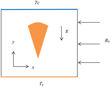
Figure 1. Schematic diagram of the model.
The governing equations are made dimensionless using the following dimensionless variables:
Applying these definitions, the following dimensionless equations are obtained.
(5)
(6)
(7)
(8)
where,
Prandtl number, ; (ratio of viscous to thermal diffusion rates, which
indicates the ratio or dominance of heat transfer mode-convection over conduction)
Hartmann number, ; (ratio of electromagnetic force to the viscous force)
Grashof number, ; (ratio of the buoyancy to viscous force acting on a fluid)
Rayleigh number, ; (product of Gr and Pr. It also indicates the ratio or dominance of heat transfer mode-convection over conduction, but incorporates the buoyancy force)
The dimensionless boundary conditions become:
at bottom wall and heated conical body (at higher constant temperature)
at top wall (at lower constant temperature)
at side walls (thermally insulated)
Fluid pressure at the inside and on the walls of the cavity
3. Numerical Procedure
The above system of equations is solved along with the boundary conditions shown above, by finite element method. This technique is described various researchers such as Taylor and Hood [11] , Reddy [12] , and Dechaumphai [13] . In this method, the solution domain is discretized into finite element mesh. Then the nonlinear governing equations are transferred into a system of integral equations by applying the Galerk in weighted residual method. Gauss quadrature method is used to perform the integration involved in each term of these equations. The nonlinear algebraic equations thus obtained are modified by imposing boundary conditions. Then Newton’s method is used to transform these modified equations into linear algebraic equations, and then these linear equations are solved by applying the triangular factorization method.
4. Results and Discussions
The calculations are performed for Prandtl number Pr = 0.71, the Rayleigh number Ra = 10, 1000, 100,000; and for Hartmann number Ha = 0, 20, 50, 100. The results are illustrated with streamlines, velocity profiles, and isotherms. Several observations can be made from the results, which are discussed next, according to the orientation of the cone.
4.1. Vertical Orientation
Streamlines: Figure 2 shows the streamlines for vertical orientation of the cone. At first there is no magnetic field impressed (Ha = 0), and Ra is increased from 10 to 100,000. The streamlines look almost the same for Ra = 10 and Ra = 1000. However, the velocities increased by order of magnitude, as indicated by the color legend (Figure 2(a) and Figure 2(b)). At Ra = 10, the velocity range is 0.0005 - 0.004 m/s, whereas for Ra = 1000, the range is 0.05 - 0.40 m/s. The streamline pattern is symmetrical, and there are two vortices on the left and right side of the cone. The maximum velocity occurs at the narrowest passage between the cone and the cavity wall. At Ra = 100,000 two additional vortices appear on the top-left and top-right corner of the cavity. The velocity range increased to 10 - 60 m/s (Figure 2(c)). Keeping Ra fixed at 100,000; a magnetic field is impressed with increasing intensity. At a modest magnetic field of Ha = 20, the velocities reduced somewhat, but there is a noticeable change in the streamline pattern. The additional two vortices disappeared (Figure 2(d)). At Ha = 50, the velocities reduced further, and the streamlines look very similar to the first case (Figure 2(a) and Figure 2(e)). However, the position of the vortices is noticeably different than the first case. Further reduction of velocity is attained by increasing Ha to 100, but the streamlines remained almost the same (Figure 2(f)).
Velocity profiles: The y-component of velocity along two different lines parallel to the x-axis (y = 0.15 and y = 0.50) are presented. Figure 3 shows the effect of Ra and Ha on y-component of velocity at y = 0.15. First, the effect of Ra is studied while keeping Ha = 0. The resulting velocity profiles are shown in Figure 3(a) and Figure 3(b). The velocity is zero at x = 0 and x = 1, which indicate no-slip condition at the cavity wall. Velocity becomes maximum at two locations, at x = 0.20 and x = 0.80. The profile remains the same with increasing Ra, however, the velocity increases by orders of magnitude. It shows the very strong influence of Ra on the velocity field, as one should expect. Next, keeping the Ra constant at 100,000; Ha is increased from 0 to 20, 50, and 100. Figure 3(c) shows the four profiles corresponding to the four values of Ha. It can be clearly seen that increasing Ha suppressed the velocities and eventually the profile lost its original shape. These observations fully agree with the observations on the streamlines as discussed in the previous section. It can be surmised that by applying a sufficiently strong magnetic field, the fluid movement can be stopped altogether.
Figure 4 shows the effect of Ra and Ha on y-component of velocity at y = 0.50, which passes through the cone. The velocity becomes zero at four locations (x = 0, 0.4, 0.6 and 1), indicating no slip condition at the cavity walls and on the
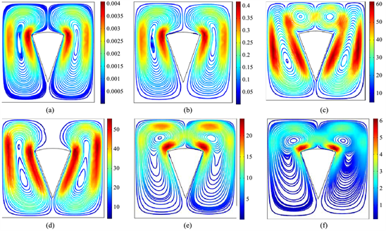
Figure 2. Streamlines for different values of Ra and Ha for vertical orientation of the cone. (a) Ha = 0; Ra = 10; (b) Ha = 0 Ra = 1000; (c) Ha = 0; Ra = 1e5; (d) Ha = 20; Ra = 1e5; (e) Ha = 50; Ra = 1e5; (f) Ha = 100; Ra = 1e5.
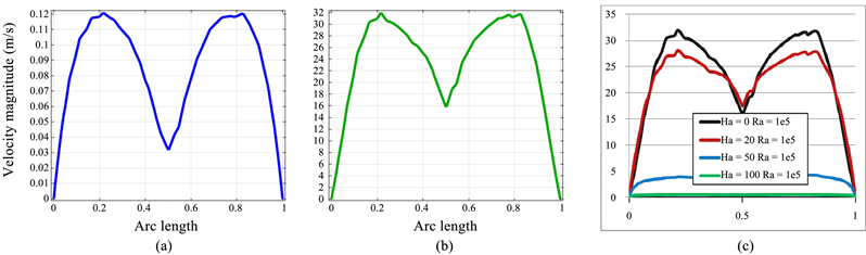
Figure 3. Effect of Ra and Ha on y-component of velocity at y = 0.15. (a) Ha = 0; Ra = 1000; (b) Ha = 0; Ra = 1E5; (c) Different Ha with Ra = 1e5.
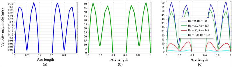
Figure 4. Effects of Ra and Ha on y-component of velocity at y = 0.50. (a) Ha = 0; Ra = 1000; (b) Ha = 0; Ra = 1E5; (c) Different Ha with Ra = 1e5.
conical body. Here also it is seen that the velocity increases by orders of magnitude with increasing Ra. Velocity peaks at four locations approximately at x = 0.1, 0.3, 0.7, and 0.9 (Figure 4(a) and Figure 4(b)). It is also seen that increase of Ha has retarding effect on the velocity (Figure 4(c)), similar to the effects observed in Figure 3(c).
Isotherms: Figure 5 shows the isotherms for different values of Ra and Ha. The legend shows the values of θ, the dimensionless temperature whose value range is 0 - 1. At first Ha is kept at 0 and Ra is increased from 10 to 100,000. The isotherms show clear differences in shape as well as in spread (Figure 5(a) and Figure 5(b)). Next, Ra is kept constant at 10, and Ha is increased all the way to 100. There is no noticeable difference between Ha = 50 and 100 (Figure 5(c) and Figure 5(d)). The calculations are repeated with Ra = 100,000. Now the differences are clear between Ha = 20 and Ha = 100 (Figure 5(e) and Figure 5(f)). For high Ra, the isotherms become smoother, closer to one another, and more uniformly spread with increasing Ha. The reason for this behavior is that the application of magnetic force on the MHD fluid retards the fluid flow, so the fluid particles are slowed down. This same phenomenon was observed with streamlines and velocity profiles as well (Figures 2-4). Since convective heat transfer mainly depends on the fluid movement, any restriction on the fluid movement will influence the heat transfer. The heat transfer mechanism becomes more like conduction than convection. The temperature distribution thus becomes more even, which is seen in the isotherms. It is also observed that the isotherms are symmetric around the cone. It can be said that Ha does not have much effect on heat transfer with low Ra, but has very visible effects with high Ra. Moreover, high Ra with high Ha results in the same isotherm pattern and consequently same heat transfer which could be achieved with low Ra and low Ha.
4.2. Left Inclined Orientation
Streamlines: Figure 6 shows the streamlines for left inclined orientation of the cone. The results are presented in the same sequence as that for the vertical orientation of the cone. At first Ha = 0, and Ra is increased from 10 to 100,000. There is no appreciable change in the streamlines between Ra = 10 and Ra = 1000; but the velocities increase by an order of magnitude, as indicated by the color legend (Figure 6(a) and Figure 6(b)). The streamline pattern is not symmetrical, and there is only one vortex on the right side of the cone. At Ra = 100,000; one additional vortex appear on the top-left corner of the cavity (Figure 6(c)). Keeping Ra fixed at 100,000; Ha is increased to 20, 50, and 100. The additional vortex vanishes with increasing Ha and the streamlines become very similar to ones developed before (Figure 6(a) and Figure 6(b)). However, the reductions in velocities are significant at each step.
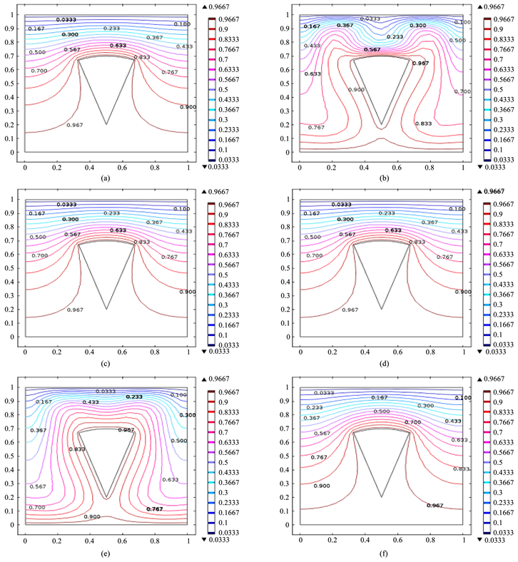
Figure 5. Isotherms for different Ha and Ra for vertical orientation of the cone. (a) Ha = 0, Ra = 10; (b) Ha = 0, Ra = 1e5; (c) Ha = 50, Ra = 10; (d) Ha = 100, Ra = 10; (e) Ha = 20, Ra 1e5; (f) Ha = 100, Ra = 1e5.
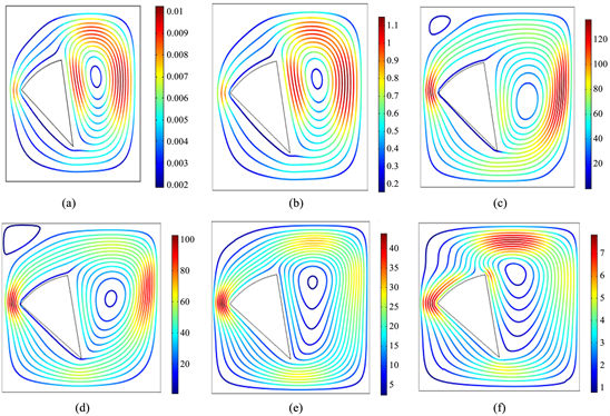
Figure 6. Streamlines for different values of Ra and Ha for left inclined orientation of the cone. (a) Ha = 0; Ra = 10; (b) Ha = 0 Ra = 1000; (c) Ha = 0; Ra = 1e5; (d) Ha = 20; Ra = 1e5; (e) Ha = 50; Ra = 1e5; (f) Ha = 100; Ra = 1e5.
Isotherms: Figure 7 shows the isotherms for different values of Ra and Ha. At first Ha is kept at 0 and Ra is increased from 10 to 100,000. The isotherms show clear differences in shape as well as in spread (Figure 7(a) and Figure 7(b)). At high Ra, the distortion is more prominent, and isotherms closer to the hot body are developed (Figure 7(b)). Next, calculations are repeated for Ha = 20, 50, and 100, with Ra = 100,000 (Figure 7(c) and Figure 7(d)). For high Ra, the isotherms become smoother, closer to one another, and more uniformly spread with increasing Ha. The same reasoning, discussions and conclusion presented for the vertical cone are also applicable here.
4.3. Right Inclined Orientation
The results are very similar to those for the left inclined orientation. Both the streamlines and isotherms look almost like mirror image of the left inclined orientation. Therefore detailed discussions will be redundant. However, the figures are presented for the sake of completeness.
Figure 8 shows the streamlines and Figure 9 shows the isotherms. The same reasoning, discussions and conclusion presented in the previous sections are also applicable here.
5. Conclusions
The effects of Ra and Ha on the fluid flow and heat transfer are investigated in a square cavity filled with MHD fluid, with a heated conical object inside the cavity. With increasing Ra, the velocity of the fluid particles increases significantly and the streamlines also show visible changes in shape. Ha affects the flow by retarding the fluid movement. Therefore, increasing Ha influences the streamlines, fluid velocities, and heat transfer. However, the effect of Ha is not significant for low values of Ra. It is also noted that the combination of low or zero Ha with low Ra produces very similar results with high Ha and high Ra. It can be said
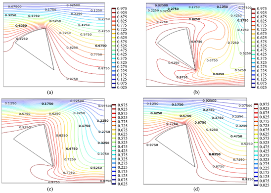
Figure 7. Isotherms for different Ha and Ra for left orientation of the cone. (a) Ha = 0, Ra = 10; (b) Ha = 0, Ra = 1e5; (c) Ha = 50, Ra = 1e5; (d) Ha = 100 Ra = 1e5.
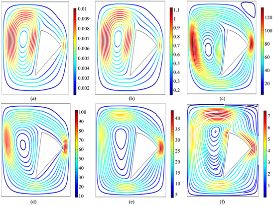
Figure 8. Streamlines for different values of Ra and Ha for right inclined orientation of the cone. (a) Ha = 0; Ra = 10; (b) Ha = 0 Ra = 1,000; (c) Ha = 0; Ra = 1e5; (d) Ha = 20; Ra = 1e5; (e) Ha = 50; Ra = 1e5; (f) Ha = 100; Ra = 1e5.
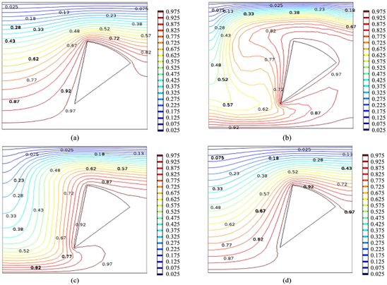
Figure 9. Isotherms for different Ha and Ra for right orientation of the cone. (a) Ha = 0, Ra = 10; (b) Ha = 0, Ra = 1e; (c) Ha = 50, Ra = 1e5; (d) Ha = 100 Ra = 1e5.
that the heat transfer mode in MHD fluid gradually changes toward conduction from convection with increasing Ha. A sufficiently large magnetic field can potentially stop fluid movement altogether. In that case, heat transfer would be fully by conduction.
Conflicts of Interest
The author declares no conflicts of interest regarding the publication of this paper.
Cite this paper
Mahjabin, S. and Alim, M.A. (2018) Effect of Hartmann Number on Free Convective Flow of MHD Fluid in a Square Cavity with a Heated Cone of Different Orientation. American Journal of Computational Mathematics, 8, 314-325. https://doi.org/10.4236/ajcm.2018.84025
References
- 1. Chamkha, A.J. (2012) Natural Convection Flow under Magnetic Field in a Square Cavity for Uniformly (or) Linearly Heated Adjacent Walls. International Journal of Numerical Methods for Heat and Fluid Flow, 22, 677-698.
- 2. Yang, K.T. (1987) Natural Convection in Enclosures. In: Kakac, S., Shah, R.K. and Aung, W., Eds., Handbook of Single-Phase Convective Heat Transfer, Wiley, New York, 401-413.
- 3. Davidson, J.H., Kulacki, F.A. and Dunn, P.F. (1987) Convective Heat Transfer with Electric and Magnetic Field. In: Kakac, S., Shah, R.K. and Aung, W., Eds., Handbook of Single-Phase Convective Heat Transfer, Chapter 9, Wiley, New York.
- 4. Moreau, M. (1990) Magnetohydrodynamics. Kluwer Academic, Dordrecht. https://doi.org/10.1007/978-94-015-7883-7
- 5. Vives, C. and Perry, C. (1987) Effects of Magnetically Damped Convection during the Controlled Solidification of Metals and Alloys. International Journal of Heat and Mass Transfer, 30, 479-496. https://doi.org/10.1016/0017-9310(87)90263-8
- 6. Bakhshan, Y. and Ashoori, H. (2012) Analysis of a Fluid Behavior in a Rectangular Enclosure under the Effect of Magnetic Field. World Academy of Science, Engineering and Technology, 61, 637-641.
- 7. Öztop, F.H. and Al-Salem, K. (2012) Effects of Joule Heating on MHD Natural Convection in Non-Isothermally Heated Enclosure. Journal of Thermal Science and Technology, 32, 81-90.
- 8. Taghikhani, M.A. and Chavoshi, H.R. (2013) Two Dimensional MHD Free Convection with Internal Heating in a Square Cavity. Thermal Energy and Power Engineering, 2, 22-28.
- 9. Bhuiyan, A.H., Alim, M.A. and Uddin, M.N. (2014) Effect of Hartmann Number on Free Convective Flow in a Square Cavity with Different Positions of Heated Square Block. International Journal of Mathematical, Computational, Physical, Electrical and Computer Engineering, 8, No. 2.
- 10. Hossain, S.A., Alim, M.A. and Saha, S.K. (2015) A Finite Element Analysis on MHD Free Convection Flow in Open Square Cavity Containing Heated Circular Cylinder. American Journal of Computational Mathematics, 5, 41-54. https://doi.org/10.4236/ajcm.2015.51003
- 11. Taylor, C. and Hood, P. (1973) A Numerical Solution of the Navier-Stokes Equations Using Finite Element Technique. Computer and Fluids, 1, 73-89. https://doi.org/10.1016/0045-7930(73)90027-3
- 12. Reddy, J.N. (1993) An Introduction to Finite Element Method. McGraw-Hill, New York.
- 13. Dechaumphai, P. (1999) Finite Element Method in Engineering. 2nd Edition, Chulalongkorn University Press, Bangkok.