World Journal of Nuclear Science and Technology
Vol.4 No.2(2014), Article ID:44750,8 pages DOI:10.4236/wjnst.2014.42011
Superficial Layer MHD Effect and Full-Cover Free Surface Flow Characterizing
Zengyu Xu, Chuanjie Pan, Xiujie Zhang, Jiming Chen
Southwestern Institute of Physics, Chengdu, China
Email: xuzy@swip.ac.cn
Copyright © 2014 by authors and Scientific Research Publishing Inc.
This work is licensed under the Creative Commons Attribution International License (CC BY).
http://creativecommons.org/licenses/by/4.0/


Received 5 December 2013; revised 2 February 2014; accepted 21 February 2014
ABSTRACT
Up to now, no a real full-cover liquid metal (LM) free surface flow have been successfully used in magnetic fusion devices as MHD instability and unavoidable rivulet flow. Recently, after we carried out a guidable free curve-surface flow on theoretically and experimentally, seeking for other way to get a full-cover free surface flow is also in implementing. The superficial layer MHD effect in free surface flow is experimentally observed. After compared and analyzed the characteristic parameters of the free surface flow, the conditions of full-cover free surface flow are found. Meanwhile, the new two parameters of surface cover ratio and rivulet flow index are introduced to characterize the flowing characteristic of the full-cover free surface flow under magnetic field. According to the analysis rule, for different liquid metal, there are the different unique conditions to meet full-cover free surface flow under magnetic field. This may be a way to solve free surface flow major MHD key issue for LM PFCs.
Keywords
Liquid Metal, Free Surface, MHD Effect, Divertor/Limiter, Fusion

1. Introduction
Up to now, no a real full-cover liquid metal (LM) free surface flow have been successfully used as liquid metal plasma facing components (PFCs), such as divertor and limiter, in magnetic fusion devices due to MHD instability and unavoidable rivulet flow [1] -[16] . Recently, after we carried out a guidable free curve-surface flow on theoretically and experimentally [17] , seeking the other way to get a full-cover free surface flow is also in implementing. Because, for capillary-porous system (CPS), which is not enough liquid metal to surface to meet the required of LM PFCs, and though a guidable free curve-surface flow can be avoided rivulet flow, but which cannot be also suitable to all PFCs. So, how to get a full-cover free surface flow remains a key issue for LM free surface flow in fusion application. In this paper, we focus on experimental implement and results understood and discussed for seeking the other way to get a full-cover free surface flow. That is aimed at to solve free surface flow major MHD key issue for LM PFCs.
2. Experiment Description
The free surface flow are measured 58 mm in width × 900 mm in length and film thickness from one to several millimeters. The angle of the flowing direction with gravity, q, is 60 degree, which is for separated the effect of gravity and MHD as well as the flow under a gradient magnetic field (see Reference [11] ). The average velocity of the free surface flow is from 0.4 to 4.34 meter per second. The magnetic field, B0, is from 0 to 1.851 Tesla. To seek for the best free surface flow, the thickness of free surface flow was designed from one millimeter to several millimeter. As current liquid metal fluid diagnosis technology limitation, the free surface flow flowing situation is recorded by normal and super high speed camera.
The experiments are carried out at Liquid Metal Experimental Loop Upgrade (LMEL-U) facility (showed in Figure 1) in Southwestern Institute of Physics, China. The parameters of the facility are below: The EM pump with a capacity of 25,000 kg/h drives the liquid metal (Ga68In20Sn12) circulation, an electromagnetic (EM) meter measured the generally average velocity (V0) and the error was better than 1.2%, the uniform magnetic field space was 80 × 170 × 740 mm, the maximum value of the magnetic field, B0, was 2 Tesla, all data are acquired by NI PXI 4071 Digital Multi-meters (26 bits resolution).
3. Results and Discussion
The MHD experimental results of the free surface flat flows are shown in from Figure 2 to Figure 7. We can
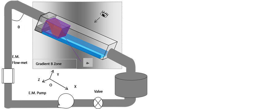
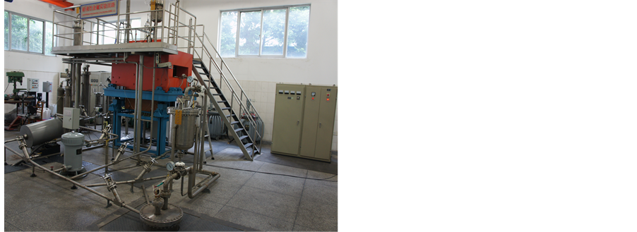
Figure 1. The photo of Liquid Metal Experimental Loop Upgrade (LMEL-U) facility (Downward) and the diagram of free surface flow MHD experiment (Upward).
found that the free surface flow, the thickness, a*, in 5.0 mm (Figure 2) is flowing in like “sword” shape under the magnetic field, B0, at 0 and 1.85 Tesla. Figure 3 and Figure 4 show the MHD experimental results of the free surface flow, the thickness, a*, in 3 mm under the magnetic field, B0, at 0 and 1.85 Tesla but at different flow beginning velocity, V0, at 2.65 m/s and 3.72 m/s. The flows are in a rivulet flow under the present magnetic field conditions. The MHD experimental results of the free surface flow, the thickness, a*, in 2.3 mm under the magnetic field, B0, at 0 and 1.85 Tesla but at different flow beginning velocity, V0, at 1.94 m/s and 4.36 m/s are shown in Figure 5 and Figure 6. The flows are evidently flowing in the superficial layer MHD effects. For the flow beginning velocity, V0, at 1.94 m/s (Figure 6), the superficial layer MHD effect made the superficial layer flowing in “line stream” flow similar to that of free curve surface flow (see Reference [17] ) and that of the free
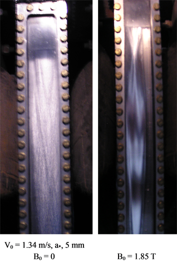
Figure 2. Free surface flow MHD effect experimental Result, film thickness, a* = 5 mm.
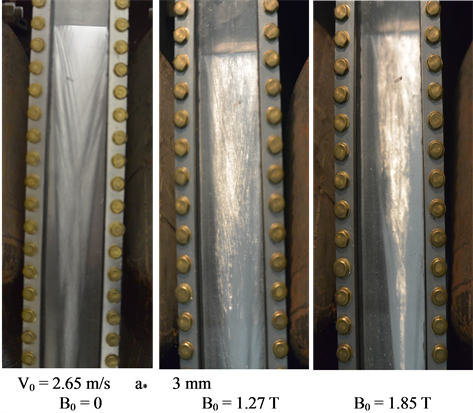
Figure 3. Free surface flow MHD effect experimental result, film thickness, a* = 3 mm.
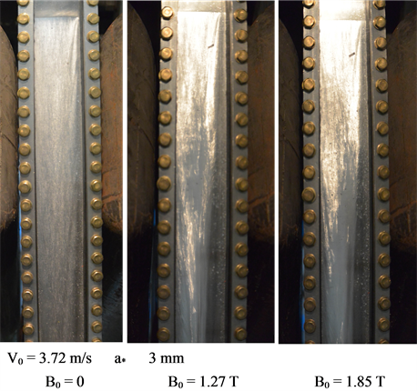
Figure 4. Free surface flow MHD effect experimental result, film thickness, a* = 3 mm.
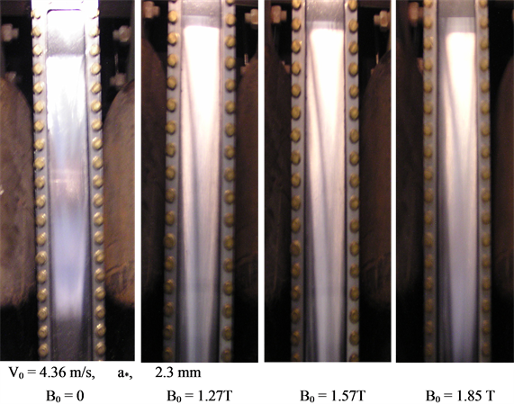
Figure 5. Free surface flow MHD effect experimental result, film thickness, a* = 2.3 mm.
surface flow, the thickness, a*, in 1.0 mm (see Figure 7). For the flow beginning velocity, V0, at 4.36 m/s (Figure 5) case, the superficial layer MHD effect made the superficial layer flowing in “dreieck” shape. Figure 7 shows MHD experimental result of the free surface flow, the thickness, a*, in 1.0 mm, the free surface flow is always flowing in “line stream” flow in despite of B0 at zero or B0 at 1.85 Tesla. Does it imply that the nature ultimate state of the free surface flow is flowing in “line stream” flow? And we note that it have a “jump” point at the transferring from flowing in the “dreieck” shape to the “line stream” flow. For the film thickness in both cases of 5 mm and 1 mm, no experimental result in different beginning velocity, V0, is presented as V0 not distinctly affected the free surface flow flowing shape. And for 1 mm in film thickness case, the work mass-GaInSn alloy is accumulated in insider of nozzle when V0 is larger than 0.4 m/s.
The experimental results reveal many phenomena that cannot be explained by current theory, such as, are there the nature ultimate state of the free surface flow—in “line stream” flow? Which related to the wet situation
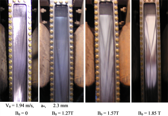
Figure 6. Free surface flow MHD effect experimental result, film thickness, a* = 2.3 mm.
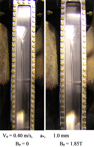
Figure 7. Free surface flow MHD effect experimental result, film thickness, a* = 1.0 mm.
of the liquid metal with solid plate? But the superficial layer MHD effect phenomenon (Figure 6 right) tells us “it has nothing to do with wet”! What is the physics behind the superficial layer MHD effect? And so on.
Though the presented phenomena cannot be clearly explained in physics by current theory, but the phenomena can understand each other and help us to get the full-cover free surface flow, such as, how to understand the free surface flowing in “sword” shape (Figure 2 right and Figure 8, left)? The free curve surface flow (Reference [17] ) and jet-film flow (Reference [11] ) as well as the present results of 1 mm in film thickness case (see Figure 7) can help us to understand the “sword” shape flow, which is combining of a free curve flow (Figure 8, middle) and a jet-film flow (Figure 8, right) at the “jump” point (Figure 7). The “jump” point at the transferring from flowing in the “dreieck” shape to the “line stream” flow. This can be understood similar to the vena contracta of the flow from a hole of thin wall container.
Now, we turn to how to get the full-cover free surface flow? For film flow thickness in 5 mm, 3 mm and 1
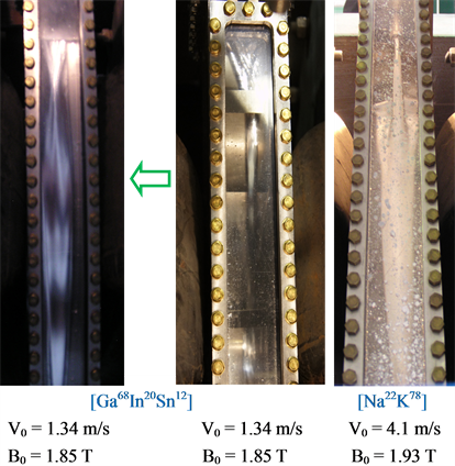
Figure 8. Compared the present experimental result with that of the free curve surface flow (Reference [17] ) and that of the jet-film flow (Reference [11] ).
mm cases, no velocities at nozzle can be gotten a full-cover free surface flow under the gradient magnetic field condition. Figure 5 and Figure 6 show that the flowing is in full-cover free surface flow though rivulets flow in their superficial layer. For well understood the conditions of full-cover free surface flowing, Table 1 listed the characteristic parameters (see Reference [18] ) of the free surface flat flow under present several different conditions. From Table 1, we find that a full-cover free surface flow can be obtained if Ha2Ca (Ha, Hartmann number, which characterises the ratio between the electromagnetic and viscous forces with respect to surface tension forces in distorting the interface. Ca, capillary number, which characterises the importance of viscous), which characterises the importance of electromagnetic forces with respect to surface tension forces in distorting the interface and FrN (N-the interaction parameter, which characterises the ratio of the electromagnetic to inertial forces), which characterises the ratio of the electromagnetic to the gravity forces, is in the same order of magnitude when Bond number, Bo, which characterises the ratio of gravitational to surface tension forces, is larger enough. After Froude number, Fr, which characterises the ratio of the inertial to gravity forces, and Bo are fixed, the Weber number, We, which characterises the relative effect of inertia with respect to surface tension, have an unambiguous determination.
For Ga68In20Sn12 alloy work mass, the calculation results indicates that Ha2Ca and FrN in the same order of magnitude can be obtained if and only if the film thickness, a*, in optimum value, at 2.3 mm. For characterizing full-cover free surface flow under magnetic field, we introduced the FrN/Ha2Ca as surface cover ratio, Sco, or . which is the reciprocal of Bo, or 1/Bo, but it has a different physic connotation during the free surface flow flowing in magnetic field. When Sco is about 1, the free surface flow will be in the full-cover free surface flow. The Ha2Ca/Fr is defined as rivulet flow index to the superficial layer of full-cover free surface flow, Rin, or
 . When Rin is larger than 1, the superficial layer will be becoming to “line stream” flow for full-cover free surface flow. For the film thickness, a* at 1 mm case, the free surface flow is flowing in the same “line stream” flow in B0 = 0 and B0 > 0 cases (the maximum B0 = 1.85 T). It is a special case, and we should understand the Sco and Rin on characterizing the similarity of the free surface flow flowing characteristic in B0 = 0 and B0 > 0 cases. According to the analysis rule, for lithium work mass, the film thickness, a*, in optimum value is at 9.0 mm. In fact, for different liquid metal, there is one different unique the film thickness to get the Ha2Ca and FrN in the same order of magnitude. It is a key issue to understand the physics behind the superficial layer MHD effect for LM plasma facing components (PFCs) R & D.
Where a* is film thickness, g is the gravitational acceleration, v0 is the average fluid velocity at the nozzle exit, B0 is the characteristic value of the external magnetic field, s is electrical conductivity, r is density, g is surface tension coefficient.
A deduction from the results (Figure 7) is that the solid surface shape carefully designed, such as with three dimension complex structural surfaces to meet the condition of liquid metal free surface flow full-cover flowing or with a simple wavy structural surface (Figure 9), perhaps, can also give an impetus to get a full-cover free surface flow, but it remains to be confirmed and studied.
4. Conclusions
In this paper, our intent in presented the free surface flow MHD experimental implement and understood the physics phenomena revealed by the experimental results. And now, the tentative conclusions can be made the below:
1) The nature state of the free surface flow—in “line stream” flow (under not exist magnetic field, B = 0) and the superficial layer MHD effect in free surface flow are observed.
2) The new two parameters of the surface cover ratio and rivulet flow index can characterize the flowing characteristic of the full-cover free surface flow under magnetic field.
3) The full-cover free surface flow can be obtained by selected appropriate characteristic parameters of the free surface flow though rivulets flow in their superficial layer.
4) Using carefully selected appropriate characteristic parameters of the free surface flow or designed the solid surface structure may be a way to solve free surface flow major MHD key issue for LM PFCs. But how to clearly understand the phenomena of the superficial layer MHD effect, more detail studied on theory and experimentally is necessary.
Meanwhile, the superficial layer MHD behavior how to affect whole free surface flow performance as LM PFCs, which need re-estimated.

Table 1. The parameters of free surface flat flow in several different conditions.
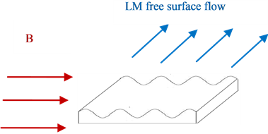
Figure 9. The solid surface with wavy structure perhaps can be also gotten a full-cover free surface flow.
Acknowledgements
National Magnetic Fusion Energy Development Project in Program 2013 GB114002, China, supports the work.
References
- Bucenieks, I., Lielausis, O., Platacis, E. and Shishko, A. (1994) Experimantal Study of Liquid Metal Film and Jet Flows in a Strong Magnetic Field. Magnetohydrodynamics, 30, 219-230.
- Muraviev, E.V. (1997) MHD Film Flow Model for Tokamak Reactor Diverter Plates. Magnetohydrodynamics, 33, 475-479.
- Mattas, R.F. (2000) ALPS Team ALPS—Advanced Limiter-Divertor Plasma-Facing System. Fusion Engineering and Design, 51-52, 127-134. http://dx.doi.org/10.1016/S0920-3796(00)00385-9
- Abdou, M.A. (2001) The APEX TEAM, on the Exploration of Innovative Concepts for Fusion Chamber Technology. Fusion Engineering and Design, 54, 181-247. http://dx.doi.org/10.1016/S0920-3796(00)00433-6
- Aleksandrova, S., Molokov, S. and Reed, C.B. (2002) Modelling of Liquid Metal Duct and Free-Surface Flows Using CFX. Report Number(s)-ANL/TD/TM02-30 TRN: US0300347.
- Ying, A.Y., Abdou, M.A., Morley, N., Sketchley, T., et al. (2004) Exploratory Studies of Flowing Liquid Metal Divertor Options for Fusion-Relevant Magnetic Fields in the MTOR Facility. Fusion Engineering and Design, 72, 35-62. http://dx.doi.org/10.1016/j.fusengdes.2004.07.004
- Morley, N.B., Smolentsev, S., Munipalli, R., Ni, M.-J., Gao, D. and Abdou, M. (2004) Progress on the Modeling of Liquid Metal Free Surface MHD Flows for Fusion Liquid Walls. Fusion Engineering and Design, 72, 3-34.
- Tanaka, T.J., Bauer, F.J., Lutz, T.J., McDonald, J.M., et al. (2004) Liquid Metal Integrated Test System (LIMITS). Engineering and Design, 72, 83-92.
- Allain, J.P., Nieto, M., Coventry, M.D., Stubbers, R. and Ruzic, D.N. (2004) Studies of Liquid-Metal Erosion and Free Surface Flowing Liquid Lithium Retention of Helium at the University of Illinois. Engineering and Design, 72, 93- 110.
- Whyte, D.G., Evans, T.E., Wong, C.P.C., West, W.P., Bastasz, R., Allain, J.P. and Brooks, J.N. (2004) Experimental Observations of Lithium as a Plasma-Facing Surface in the DIII-D Tokamak Divertor. Engineering and Design, 72, 133-147.
- Xu, Z.Y., Pan, C.J. and Kang, W.S. (2004) Experimental Observation and Theoretic Analysis MHD Effects of a Liquid Metal Jet in a Gradient Magnetic Field. Fusion Science and Technology, 46, 577-585.
- Nygren, R.E., Harjes, H.C., Wakeland, P., Ellis, R., et al. (2009) Thermal Control of the Liquid Lithium Divertor for NSTX. Fusion Engineering and Design, 84, 1438-1441. http://dx.doi.org/10.1016/j.fusengdes.2008.11.098
- Vertkov, A.V., Lyublinski, I.E., Tabares, F. and Ascasibar, E. (2012) Status and Prospect of the Development of Liquid Lithium Limiters for Stellarotor TJ-II. Fusion Engineering and Design, 87, 1755-1759. http://dx.doi.org/10.1016/j.fusengdes.2011.10.004
- Apicella, M.L., Lazarev, V., Lyublinski, I., Mazzitelli, G., et al. (2009) Lithium Capillary Porous System Behavior as PFM in FTU Tokamak Experiments. Journal of Nuclear Materials, 386-388, 821-823. http://dx.doi.org/10.1016/j.jnucmat.2008.12.238
- Lyublinski, I., Vertkov, A., Evtikhin, V., Balakirev, V., et al. (2012) Module of Lithium Divertor for KTM Tokamak. Fusion Engineering and Design, 87, 1719-1723. http://dx.doi.org/10.1016/j.fusengdes.2011.07.012
- Kugela, H.W., Allain, J.P., Bell, M.G., Bell, R.E., et al. (2012) NSTX Plasma Operation with a Liquid Lithium Divertor. Fusion Engineering and Design, 87, 1724-1731.
- Xu, Z.Y., Zhang, X.J., Pan, C.J., Liu, B., et al. (2013) Analysis and Primary Experiment Results of a Guidable Free Curve-Surface Flow for Liquid Metal PFCs. Advances and Applications in Fluid Mechanics, 13, 141-155.
- Molokov, S. and Reed, C.B. (2000) Review of Free-Surface MHD Experiments and Modeling. ANL0TD0TM99-08, Argonne National Laboratory (Unpublished).