Journal of Crystallization Process and Technology
Vol. 3 No. 2 (2013) , Article ID: 30881 , 4 pages DOI:10.4236/jcpt.2013.32009
Optical Methods in Orientation of High-Purity Germanium Crystal
![]()
1Department of Physics, University of South Dakota, Vermillion, USA; 2Department of Chemistry, University of South Dakota, Vermillion, USA.
Email: *Guojian.Wang@usd.edu
Copyright © 2013 Guojian Wang et al. This is an open access article distributed under the Creative Commons Attribution License, which permits unrestricted use, distribution, and reproduction in any medium, provided the original work is properly cited.
Received February 2nd, 2013; revised March 5th, 2013; accepted March 15th, 2013
Keywords: Reflection Method; High-Purity Germanium Crystal
ABSTRACT
Two optical methods, namely crystal facet reflection and etching pits reflection, were used to orient <100> and <111> high-purity germanium crystals. The X-ray diffraction patterns of three slices that were cut from the oriented <100> and <111> crystals were measured by X-ray diffraction. The experimental errors of crystal facet reflection method and etching pits reflection method are in the range of 0.05˚ - 0.12˚. The crystal facet reflection method and etching pits reflection method are extremely simple and cheap and their accuracies are acceptable for characterizing high purity detector-grade germanium crystals.
1. Introduction
Recently, there has been a great deal of interest in searching for dark matter and neutrinoless double-beta decay that are so called rare event physics beyond Standard Model using ton-scale high-purity germanium (HPGe) detectors with ultra-low internal radioactive backgrounds [1-8]. The high purity germanium crystal (net concentration range below 1010/cm3) was grown in pure hydrogen atmosphere. The divacancy-hydrogen center (V2H) in the crystal will cause trapping of holes which will degrade the performance of nuclear radiation detectors. In order to reduce the impact of V2H center, the dislocation density must be everywhere between 102 and 104 cm−2 [9]. For fabricating detectors, the orientation of the Ge crystal is important. High-Purity germanium crystals used for fabricating detectors are usually oriented along <100> direction [10,11]. Although an accurately oriented seed is used for growing a crystal, the grown crystal will deviate from the <100> direction because the seed rod is slightly off-center in the crucible. Therefore, the grown crystals should be oriented before fabricating detectors. X-ray diffraction is an accurate technique to orient crystals [12,13]. However, the equipment and operation of X-ray diffraction is complex.
Based on the structure and crystal growth behavior of Ge, the optical method that has been used in Si crystals [14] is used to orient Ge crystals for cutting since it is extremely simple and effective. Figure 1 shows the morphology of Ge crystal, which is from the structure data of Ge crystal [15]. The interfacial angle between (111) and (100) is 54.72 degrees. The angle between the normal line of (111) facet and another normal line of (100) facet is 54.72 degrees. These normal lines are parallel to <111> and <100> directions, respectively. The interfacial angle between (111) and (11ī) ((1ī1) or (ī11) is 70.53 degrees.
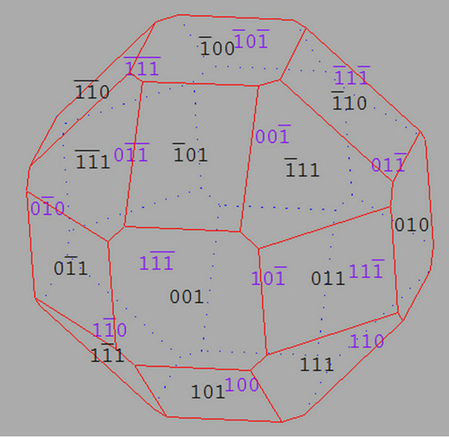
Figure 1. The morphology of Ge crystal.
For Ge crystals, because the atom density of (111) facet is the largest, the growth speed of (111) is the slowest one. Therefore, Ge crystals tend to develop (111) facets. If the axial thermal gradient is lower, three {111} facets will be formed in the enlarging process after the dash process. For crystals along <100>, there are four {111} facets and four crystal edges [110]. For Ge crystals along <111>, there are three facets and three crystal edges [110]. Therefore, the reflection of crystal facets can be used to orient the Ge crystals. On the other hand, because of the dissolution speed difference in (111) and (100) facets the etching pits reflection can also be used to orient Ge crystals. In this paper, both crystal facets reflection and etching pits reflection in the orientation of high-purity germanium crystals are discussed.
2. Experimental
2.1. Crystal Facet Reflection Method in Orientation of <100> Crystal
Figure 2 shows the geometry of orienting a <100> crystal with four {111} facets. Two Metrologic neon (He-Ne) lasers (632.8 nm) are mounted perpendicularly to a screen and pass through the holes in the screen. The two lasers and a graphite plate are then adjusted using a bubble level until paralleling with the optical table. The angle between the lasers and the long edge of the graphite plate is set to 54.72 degrees. The crystal is mounted on the graphite plate by placing one facet vertical to the lasers until the reflected lasers pass back through the two holes. The <100> orientation is thus parallel to long edge of graphite plate.
2.2. Etching Pits Reflection Method in Orientation of <100> and <111> Crystals
During etching by etchant (H2O2:HCl:H2O = 1:1:4), the dissolution speed of (111) is faster than that of the (100) plane. Therefore, for the side wall of the etching pits, only the (111) facet will be left. The bottom of the etching pit is parallel to (100) or (111) [14].
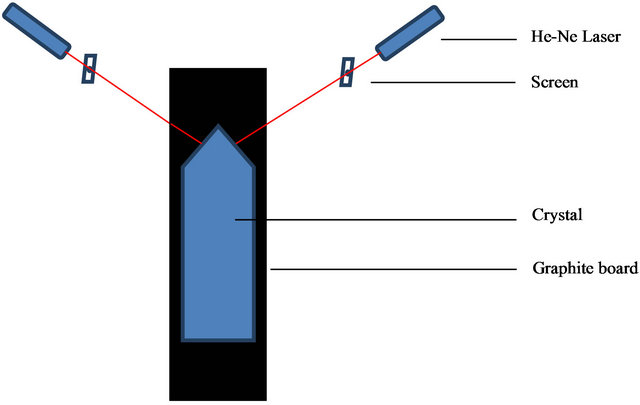
Figure 2. The geometry of <100> crystal orientation.
For (100) and (111), the etching pits are square and triangular, respectively (as shown in Figure 3). The optical system was built to determine the crystal orientation along <100> and <111>. Usually, the etching pits (dislocation) density should be larger than 500/cm2. First, the grown crystal was cut along the direction perpendicular to the seed direction. The obtained surface was polished with waterproof sandpaper until a mirror-like surface was obtained. Then the crystal was rinsed in acetone and deionized water and blown dry by nitrogen gas. The obtained surface was etched by H2O2:HCl:H2O = 1:1:4 for 7 minutes ((100) sample) and 5 minutes ((111) sample).
Figure 4 shows the screens for <100> and <111> crystals. In these pictures, the red points are a hole with diameter 2 mm. For <100> crystal, there are two white lines that intersect at the center of the hole with angle 90˚. For <111> crystal, there are three white lines that intersect at the center of the hole with angle 120˚. The laser is perpendicular to the screen and goes through the hole on the screen (as shown in Figure 5). The graphite plate is parallel to the laser. The crystal was placed on the graphite plate. The etched surface was facing to the laser. The reflected laser beam was projected on the screen. Figure 6 shows the light patterns of laser beams reflected from (100) and (111) surfaces of a Ge crystal. The experimental light patterns of laser beams reflected from the (100) and (111) surfaces of Ge crystal are shown in Figure 7. The crystal was adjusted to make the center of the reflected laser beam coincide with the marked lines on the screen. Then the crystal was fixed on the graphite plate with wax. The <100> or <111> orientation is parallel to long edge of graphite plate.
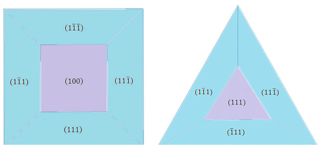
Figure 3. The etched pit diagrams of <100> (left) and <111> (right) crystals.
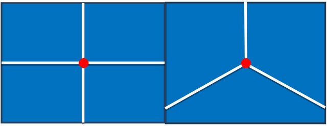
Figure 4. The screens for orientation of <100> (left) and <111> (right) crystals.

Figure 5. The geometry of crystal orientation for etching pits reflection method.

Figure 6. The light patterns of laser beam reflected from (100) and (111) surface of Ge crystal.
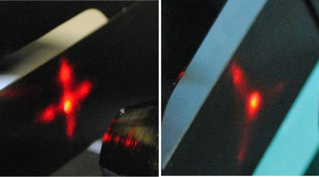
Figure 7. The experimental light patterns of light pattern of laser beam reflected (100) and (111) surface of Ge crystal.
3. Results and Discussion
The X-ray diffraction method was used to verify the accuracy of the oriented crystals. The X-ray diffraction patterns of three slices that were cut from the oriented <100> and <111> crystals were measured by X-ray diffraction using a Rigaku Ultima IV X-ray diffractometer (as shown in Figure 8). Table 1 shows the comparison of the experimental and reported results of XRD. For <100> crystal, the crystal facet reflection method is more accurate than etching pits reflection method. The experimental errors of crystal facet reflection method and etching pits reflection method are in the range of 0.05˚ - 0.12˚. The experimental errors are related to the diameter of the laser beam, the dimensional tolerances of the graphite plate and the experimenter’s ability to “eyeball” the laser alignment. However, crystal facet reflection and etching pits reflection methods are extremely simple and cheap and their accuracies are acceptable for character izing high purity detector-grade germanium crystals. The facet reflection method can be used for orienting the <100> crystal with four facets grown from lower thermal gradient and the etching pits reflection method can be
 (a)
(a)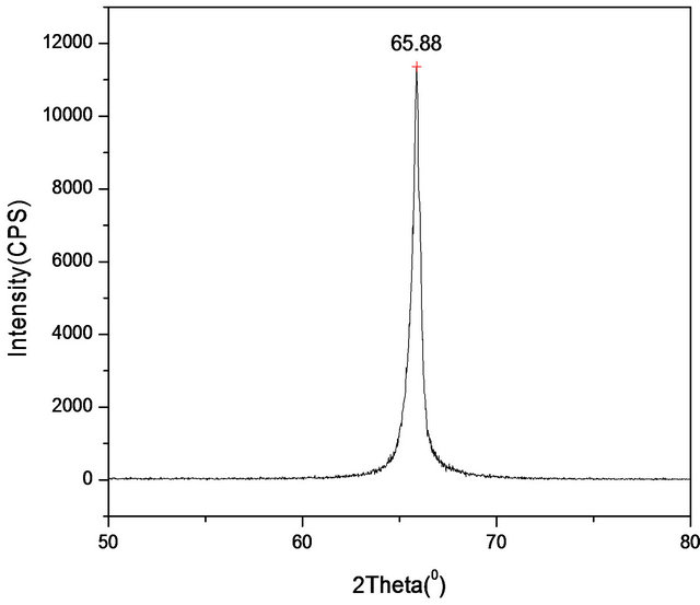 (b)
(b)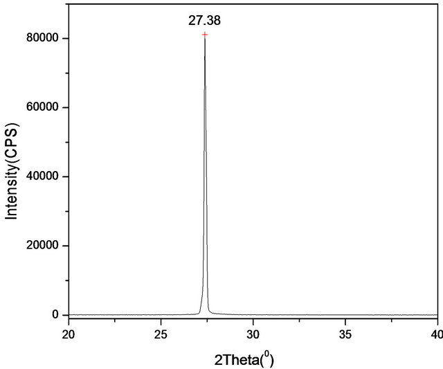 (c)
(c)
Figure 8. (a) The X-ray diffraction of (400) that was oriented by crystal facet reflection method; (b) The X-ray diffraction of (400) that was oriented by crystal etching pits reflection method; (c) The X-ray diffraction of (222) that was oriented by crystal etching pits reflection method.
used for the <100> or <111> crystal with dislocation density larger than 500/cm2.
Table 1. Comparison of experimental and reported results of XRD.
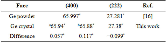
aCrystal facet reflection method; bCrystal etching pits reflection method.
4. Acknowledgements
This work is supported by DOE grant DE-FG02- 10ER46709 and the state of South Dakota.
REFERENCES
- F. T. Avignone III, S. R. Elliott and J. Engel, “Double Beta Decay, Majorana Neutrinos, and Neutrino Mass,” 2007.
- The Majorana Collaboration, A. Barabash, et al., “The Majorana Neutrinoless Double-Beta Decay Experiment Pre-Conceptual Design Report,” 2006.
- The Majorana Collaboration, R. Gaitskell, et al., “White Paper on the Majorana Zero-Neutrino Double-Beta Decay Experiment,” 2003.
- P. S. Barbeau, J. I. Collar and O. Tench, “Large-Mass Ultralow Noise Germanium Detectors: Performance and Applications in Neutrino and Astroparticle Physics,” Journal of Cosmology and Astroparticle Physics, Vol. 9, 2007, p. 009.
- D.-M. Mei, Z.-B. Ying and S. R. Elliott, “Cosmogenic Production as a Background in Searching for Rare Physics Processes,” Astroparticle Physics, Vol. 31, No. 6, 2009, pp. 417-420. doi:10.1016/j.astropartphys.2009.04.004
- E. Figueroa-Feliciano, “Towards Direct Detection of WIMPs with the Cryogenic Dark Matter Search,” AIP Conference Proceedings, Vol. 1200, 2010, pp. 959-962. doi:10.1063/1.3327773
- Z. Ahmed, et al., “Dark Matter Search Results from the CDMS II Experiment,” Science, Vol. 327, No. 5973, 2010, pp. 1619-1621. doi:10.1126/science.1186112
- A. J. Anderson, J. M. Conrad, E. Figueroa-Feliciano, K. Scholberg and J. Spitz, “Coherent Neutrino Scattering in Dark Matter Detectors,” Physical Review D, Vol. 84, 2011, pp. 013008-1-013008-8. doi:10.1103/PhysRevD.84.013008
- P. Glasow and E. E Haller, “The Effect of Dislocation on the Energy Resolution of High-Purity Germanium Detectors,” IEEE Transactions on Nuclear Science, Vol. 23, No. 1, 1976, pp. 92-96. doi:10.1109/TNS.1976.4328221
- R. N. Hall, “Chemical Impurities and Lattice Defects in High-Purity Germanium,” IEEE Transactions on Nuclear Science, Vol. 21, No. 1, 1974, pp. 260-272. doi:10.1109/TNS.1974.4327470
- W. L. Hansen and E. E. Haller, “A View of the Present Status and Future Prospecis of High Purity Germanium,” IEEE Transactions on Nuclear Science, Vol. 21, No. 1, 1974, pp. 251-259. doi:10.1109/TNS.1974.4327469
- J. M. EI-Hussaini and S. T. Stephenson, “Single-Crystal Orientation Effects in K X-Ray Absorption Spectra of Ge,” Physical Review, Vol. 109, No. 1, 1958, pp. 51-54. doi:10.1103/PhysRev.109.51
- C. Marin and E. Dieguez, “Orientation of Single Crystals by Backreflection Laue Pattern Simulation,” World Scientific Publishing, Singapore, 1999. doi:10.1142/3290
- S. D. Al-Alagawi, M. A. Aboud and A. K. Ali, “Optical Method to Determine the Orientation of Monocrystalline Silicon Wafers,” Engineering and Technology, Vol. 25, 2007, pp. 950-954.
- C. Filippi, D. J. Singh and C. J. Umrigar, “All-Electron Local-Density and Generalized-Gradient Calculations of the Structural Properties of Semiconductors,” Physical Review B, Vol. 50, No. 20, 1994, pp. 14947-14951. doi:10.1103/PhysRevB.50.14947
- A. Smakula and J. Kalnajs, “Precision Determination of Lattice Constants with a Geiger-Counter X-Ray Diffractometer,” Physical Review, Vol. 99, No. 6, 1955, pp. 1737-1743. doi:10.1103/PhysRev.99.1737
NOTES
*Corresponding author.