Engineering
Vol. 2 No. 11 (2010) , Article ID: 3164 , 4 pages DOI:10.4236/eng.2010.211108
Experimental Study of the Effects of Submerged Dikes on the Energy and Momentum Coefficients in Compound Channel
1Water Department, Shiraz University, Shiraz, Iran
2School of Civil and Environmental Engineering, University of Technology, Sydney, Australia
E-mail: keshavrz@shirazu.ac.ir, James.ball@uts.edu.au
Received July 21, 2010; revised September 28, 2010; accepted October 13, 2010
Keywords: Submerged Vane, Flow Structure, Compound Channel, Velocity Meter (Micro-ADV)
ABSTRACT
This paper aims to understand the flow structure around submerged dike in the main channel and flood plain of a compound cross section. The study undertaken to develop this understanding was carried out in a laboratory flume using a submerged vane installed at a 90 degree angle to the bank. In order to study the flow structures, the flow velocity was measured using a three-dimensional Acoustic Doppler Velocity meter (micro-ADV) with data collection rate of 50 Hz. These flow velocity measurements were taken at 500 points on a regular grid. As the tests were undertaken with turbulent flow, these conditions were subcritical. Furthermore, all the tests were undertaken using a fixed bed. The results obtained showed that the momentum transfer and the kinetic energy reduced in two directions. Also the energy and momentum coefficients decreased significantly with the installation of the submerged vane inside the main channel. Finally, streamlines were found to deviate from the side walls of channel into the main channel.
1. Introduction
Urban planning, industrial development and agricultural investment necessitates a better understanding flood plain management and flow hydraulics in channels with flood plains. One of the important issues in flood and seasonal rivers is the destruction of flood plains and their interface with the main river channel. A method for protection of river bank is to construct a spur dike to divert streamlines from the bank. The spur dike normally is designed for non-submerged conditions. Thereby in flood events the spur dikes are firstly submerged and therefore acts as a submerged vane.
Hydraulic parameters including velocity, discharge, shear stress and vortex are the causes of river bed erosion and river bank failure and finally the destruction of river walls (Figure 1). Protective structures such as dikes, spur dikes and submerged vanes can prevent the occurrence of river bed erosion and river bank failure in river. A submerged vane is a developed form of depth panels which were used by Odggard et al. [1] to prevent the erosion of the outside bank of a river. Since then, these submerged vanes have been used for a variety of purposes in different projects including the prevention of the accumulation of sediment in turn-out openings and near the pump stations. The height of these vanes is higher than the average low-water level, but less than the height of common spur dikes. This kind of structure is suitable for modifying river paths with sandy beds, and it may also be effective for rivers with gravel beds.
Submerged dikes are short structures that are approximately parallel to axial river flow and they are placed with a smaller angle to modify the velocity distribution and flow streamlines path [2]. Knight and Demetriou [3] measured the velocity distribution in compound channels with rectangular sections. They observed high momentum transfer and skewed velocity profile in the interface between the main channels and flood plain. Laboratory studies by Sellin [4], Fukuoka and Fujita [5], Tominaga and Nezu [6] and Ikeda et al. [7] confirmed that a large difference in the velocities between the main channel and the floodplain generates large horizontal eddies (organized plan form vortices) in the shear layer when flooding occurs in a shallow flood

Figure 1. An image of the destruction of river bank.
plain. These effects have been observed also by Shiono and Knight [8], Naot et al. [9] and Shiono and Scott [10]. They found that secondary currents have a significant influence on momentum transfer and boundary shear stress. Also studies by Odgaard and Kenndey [1] and Odggard and Wang [11] indicated that, depending on the installation angle of submerged vane, the flow pattern creates a secondary vortex around the vane and changes the shear stress and the velocity distribution patterns thereby changing the sediment transfer trend. Also the shear layer generated by the difference in velocities between the main channel and flood plain develops vortices in the longitudinal axis. Myers and Bernnan [12] analyzed momentum transfer from the main channel to the flood plain, and showed that the discharge and velocity decrease more significantly on the flood plain than on the main channel. Al-Khatib and Gogus [13] found that the width of flood plain do not have a significant influence on the values of energy and momentum coefficients.
In spite of many previous studies investigating flows in compound channels, most of the studies were undertaken in a compound channel without a submerged vane. As a result, the flow structure at the interface of main channel/ flood plain when a submerged vane is present remains poorly understood.
Therefore, the purpose of the research reported herein was to study the flow structure at the interface of flood plains and main channels in compound channels with the present of submerged vanes. Also the effect of submerged vane for reduction of momentum transfer from the main channels to the flood plains will be investigated in this paper.
2. Materials and Methods
In this experimental study, all the tests were carried out in the Hydraulic Laboratory of the Water Engineering Department in Shiraz University. The tests were undertaken in a glass flume with a bed slope of 0.002, and with length, width and height dimensions of 15 m, 0.7 m and 0.6 m respec-tively.
Flow inside the flume was measured using an electromagnetic flow meter and a V-Notch Weirs with a tip angle of 90o. In order to control the flow depth, a sliding gate was used at the downstream end of the flume. The required distance from the inlet of the flume for flow conditions to be fully developed was calculated to be 5.65 m. For more accurate data, the vane was installed at a distance of 11m from the beginning of the channel.
An impermeable submerged vane with a thickness of 2 mm, length of 5 cm and width of 5 cm was installed at a 90 degree angle to the bank. The dimensions of the compound cross section and the location of the vane installation are shown in Figure 2. In the study by Peterson [14] it was pointed out that the contraction of section by the structure should not exceed 30 percent of the river width. Therefore, in the experimental study presented herein, the contraction of the section by the structure was

Figure 2. Cross section of experimental flume with compound channel (all dimensions are in centimeter).
set to at 16% of the width.
Additionally, the flow depths on the flood plains were adjusted to allow use of the velocity meter probe to collect velocity data in the interface between the main channel and the flood plains. As a result, the  ratio (d is the flow depth on the flood plain while h is the flow depth in the main channel) was selected to be within the range of 0.3 to 0.4. (Table 1)
Finally, velocity data was captured at 500 single points in each of the experimental tests reported herein. A three-dimensional velocity-meter (Acoustic Doppler Velocity meter) was used for measu-ring the velocity fluctuations with a sample frequency rate of 50 Hz.
3. Results
3.1. Velocity Analysis
After collection of the velocity data at 500 grid points around the submerged vane, the data was processed using developed computer program and win-ADV software (SonTec). Velocity fluctuations ( ) were obtained in the horizontal, vertical and transverse directions using:
 (1)
(1)
 (2)
(2)
 (3)
(3)
where u, v and w are the instantaneous velocity in the horizontal, vertical and transverse directions, respectively and ,
,  and
and  are the fluctuations in the horizontal, vertical and transverse directions, respectively. The average instantaneous velocity is obtained using the following relations (n is the number of samples):
 (4)
(4)
 (5)
(5)
 (6)
(6)
The velocity fluctuations were computed for all the ratios of  for two conditions which were the channel with installation of a submerged vane and the channel without the installation of a submerged vane. The flow lines and the velocity contours were plotted in each of three directions using the Tec plot Software. Shown in Figures 3 and 4 are examples of these plots with flow lines and velocity contours presented in these figures for values of
  of 0.375 and 0.4 for the two conditions. In Figures 3 and 4 it can be seen that a flow vortex appeared for all ratios of
  and especially when the submerged vane was not installed in the main channel. The generated vortex in the interaction area between the main channel and the flood plain produce scouring, but after installation of a vane inside the main channel, this vortex disappeared and the flow lines were diverted towards the center of the main channel. Concerning the transversal velocity direction, it is pointed out that the submerged vane changes the direction of the velocity near the vane and at the interface between the main channel and the flood plains. But concerning the velocity in the vertical direction, it is pointed out that the velocity vectors change their direction upwards in the installation area of the submerged vane.
3.2. Coefficients of  and
and 
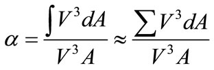
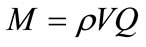
As part of this study, the energy and momentum coefficients were computed and the effect of the installed submerged vane on these coefficients was analyzed. The energy coefficient value was calculated using:
 (7)
(7)
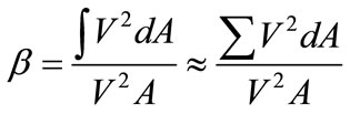
While the momentum coefficient was calculated using:
 (8)
(8)
The cross sectional average velocity in the denominator of the fraction was determined using:
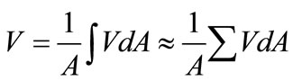 (9)
(9)
For comparison of the energy and momentum coefficients with different  ratios, a sectional interface was used for calculating of the coefficients (see Table 2). It was found that, with an increase of the
  ratio, the coefficients decrease; this decrease is shown in Figures 5 and 6 where the calculated coefficients are shown as a function of the
  ratio. As shown in these figures, it is obvious that the energy and momentum coefficients decrease with an increase in the
  ratio. However, the decrease in the
  coefficient is greater than that for the
  coefficient. Furthermore, as shown in Figures 5 and 6, the value of the energy and momentum coefficients with and without submerged vanes are consistent for d/h < 0.35 but the value of the energy and momentum coefficients with and without submerged vanes are not consistent for d/h > 0.35. This is due to the effect of submerged vane on the production of a more uniform velocity distribution in the compound channel. Also with an increase of the
  ratio and approaching the 1, the channel converts to the simple channel and consequently the velocity distribution become more uniform.
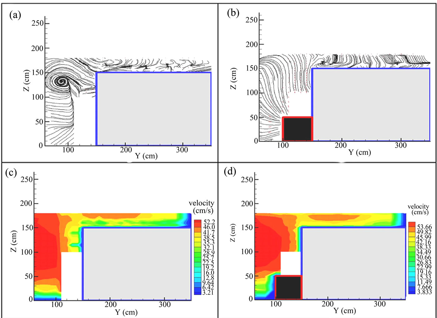
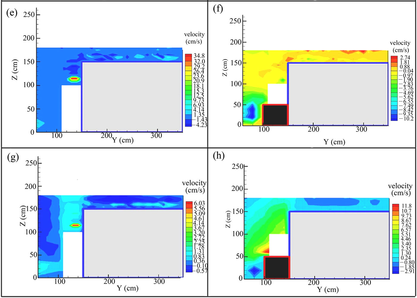
Figure 3. Streamlines and velocity in different directions; (c) and (d) Horizontal; (e) and (f) Transverse; (g) and (h) Vertical for . (Left column are without vane and right column with the vane).
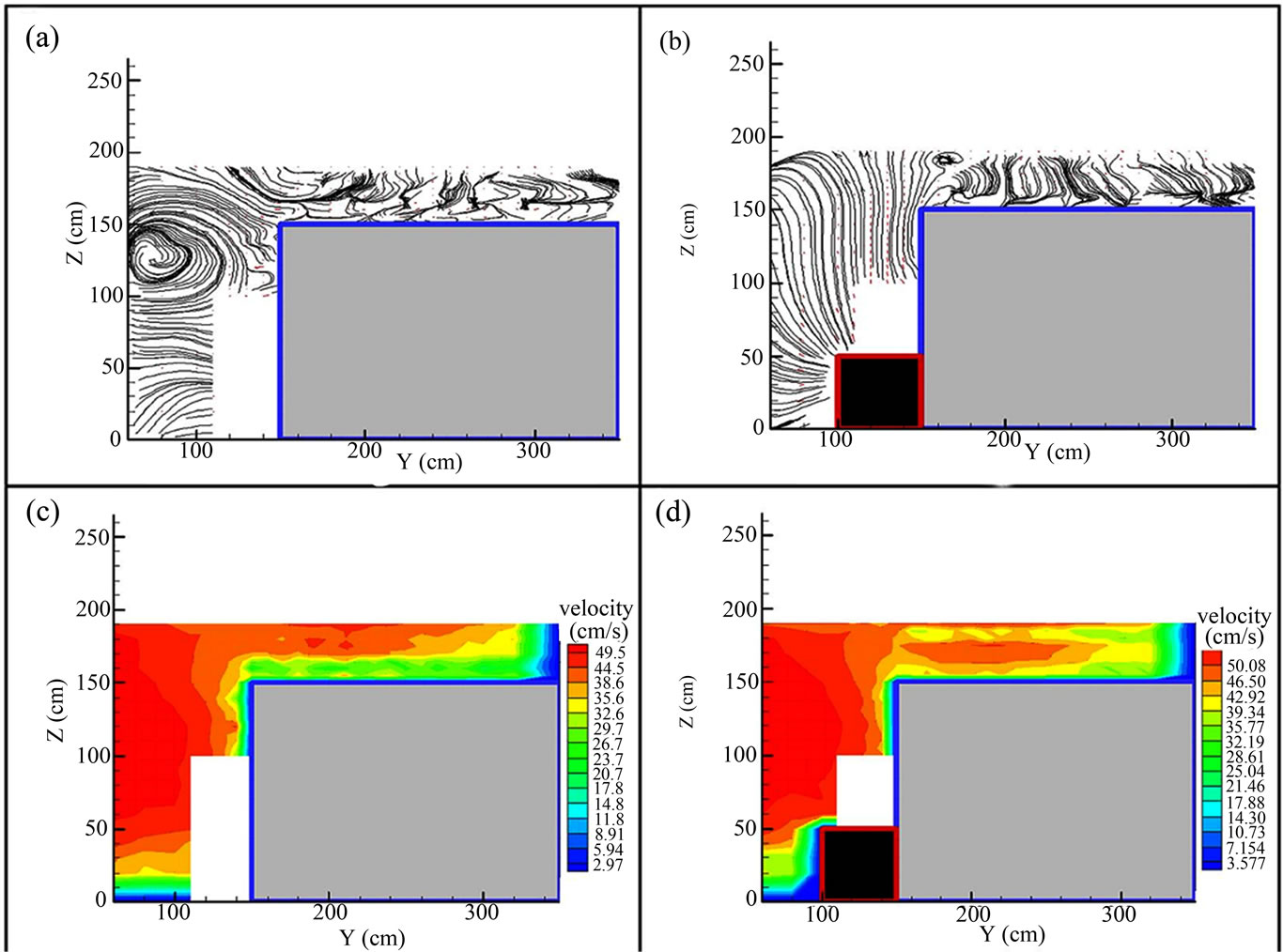

Figure 4. Streamlines and velocity in different directions; (c) and (d) Horizontal; (e) and (f) Transverse; (g) and (h) Vertical for . (Left column are without vane and right column with the vane).

Table 1. Hydraulic conditions of the experimental tests.

Table 2. The  and
and  values for a sectional interface in compound channels in different ratios of
 .
.

Figure 5. The relation of energy coefficient ( ) with different ratios of
 .
.

Figure 6. The relation of momentum coefficient ( ) with different ratios of
 .
.
Seckin et al. [15] presented a relationship between the energy coefficient and the momentum coefficient for a compound channel and showed that the coefficients decrease with an increase in the discharge. The results of Seckin et al. [15] for the condition of no submerged vane are similar to the results presented herein.
3.3. Momentum Transfer Value
The value of momentum transfer coefficient at the interface between the main channel and the flood plains were calculated also. This momentum transfer coefficient was calculated for velocity in the transversal direction using the following equations
 (10)
(10)
The elementary discharge of flow is given by
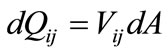 (11)
(11)
where  and
and  are discharge and average velocity at each element, and
 (12)
(12)
In which  is the width of each element, and dy is the height of each element.
Therefore, for each elementary momentum of flow can be expressed as;
 (13)
(13)
where  is elementary momentum for each of flow element.
Total momentum at each section is given by
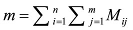 =
=
 (14)
(14)
where m is the total momentum at inflow or outflow cross sectional area, and the subscripts i and j refer to each element.
Using the above equations, the total momentum transfer for the interface between the main channel and the flood plains with the conditions of submerged vane and without the submerged vane were computed and the percentage of reduction is presented in Table 3.
3.4. Kinetic Energy Value
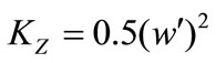
The magnitude of the kinetic energy is obtained from the fluctuations of the instantaneous velocity in each of the directions using:
 (15)
(15)
 (16)
(16)
 (17)
(17)
Results from these calculations are presented in Table 4. It is obvious from consideration of Table 4 that the kinetic energy in the flow direction increases with installation of a submerged vane. In the vertical direction, the kinetic energy without the vane was negative in the downward direction resulting in the potential for erosion while with the submerged vane it is positive or in the upward direction and hence has a significantly reduced potential for erosion. For the transverse direction the kinetic energy increases with the installation of the submerged vanes and therefore it reduces the potential for bank erosion at the side of compound channel.

Table 3. The percentage of momentum reduction in the compound channel with the installation of the vane in the main channel.
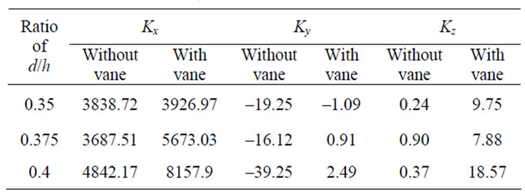
Table 4. The kinetic energy values in the compound channel in different ratios of .
.
4. Conclusions
Presented herein have been the results obtained from an experimental test undertaken to understand the flow structures at the interface of a main channel and flood plain, and around submerged vanes in the main channel of a compound cross section. To study these flow structures, flow velocity was measured using a three-dimensional Acoustic Doppler Velocity meter (micro-ADV) at 500 grid points and at a rate of 50 Hz. From the results obtained, it was concluded that the momentum transfer and the kinetic energy reduced in two directions and that the energy and momentum coefficients decrease significantly with the installation of a submerged vane inside the main channel. In addition, streamlines were found to deviate from the side walls of the main channel. Finally, the value of the energy and momentum coefficients with and without submerged vanes were very consistent for d/h < 0.35, but were found to be inconsistent for d/h > 0.35.
5. REFERENCES
- A. J. Odgaard and J. F. Kenndey, “River-Bend Bank Protection by Submerged Vanes,” ASCE Journal of Hydraulic Engineering, Vol. 109, No. 8, 1983, pp. 1161- 1173.
- F. G. Charlton, “River Stabilization and Training in Gravel-Bed Rivers,” Wiley, New York, 1982, pp. 635- 657.
- D. W. Knight and J. D. Demetriou, “Flood Plain and Main Channel Flow Interaction,” ASCE Journal of Hydraulic Engineering, Vol. 109, No. 8, 1983, pp. 1073-1092.
- R. H. J. Sellin, “A Laboratory Investigation into the Interaction between Flow in the Channel of a River and that over Its Floodplain,” La Houille Blanche, Vol. 19, No. 7, 1964, pp. 793-801.
- S. Fukuoka and K. Fujita, “Prediction of Flow Resistance in Compound Channels and Its Application to Design of River Courses,” JSCE Journal of Hydraulic, Coastal and Environmental Engineering, in Japanese, Vol. 411, No. II-12, 1989, pp. 63-72.
- A. Tominaga and J. Nezu, “Turbulent Structure in Compound Open Channel Flow,” ASCE Journal of Hydraulic Engineering, Vol. 117, No. 1, 1991, pp. 21-41.
- S. Ikeda, N. Murayam and T. Kuga, “Stability of Horizontal Vortices in Compound Open Channel Flow and their 3-D Structure,” JSCE Journal of Hydraulic, Coastal and Environmental Engineering, in Japanese, Vol. 509, No. II-30, 1995, pp. 131-142.
- K. Shiono and D. Knight, “Turbulent Open Channel Flows with Variable Depth across the Channel,” Journal of Fluid Mechanics, Vol. 222, 1991, pp. 617-647.
- D. Naot, I. Nezu and H. Nakagawa, “Hydrodynamic Behavior of Compound Rectangular Open Channels,” ASCE Journal of Hydraulic Engineering, Vol. 119, No. 3, 1993, pp. 390-408.
- K. Shiono and C. F. Scott, “Predictions of Solute Transport in a Compound Channel Using Turbulence Models,” Journal of Hydraulic Research, Vol. 41, No. 3, 2003, pp. 247-258.
- A. J. Odgaard and Y. Wang, “Sediment Management with Submerged Vanes,” ASCE Journal of Hydraulic Engineering, Vol. 117, No. 3, 1991, pp. 267-283.
- W. R. C. Myers and E. K. Bernnan, “Flow Resistance in Compound Channel,” Journal of Hydraulic Research, Vol. 28, No. 2, 1990, pp. 141-155.
- I. Al-Khatib and M. Göğüş, “Momentum and Kinetic Energy Coefficients in Symmetrical Rectangular Compound cross Section Flumes,” Turkish. Journal of Engineering and Environmental Science, Vol. 23, No. 3, 1999, pp. 187-197.
- M. S. Peterson, “River Engineering,” Prentice Hall, Englewood Cliffs, 1986.
- G. Seckin, M. Ardiclioglu, H. Cagatay, M. Cobaner and R. Yurtal, “Experimental Investigation of Kinetic Energy and Momentum Correction Coefficients in Open Channels,” Scientific Research and Essay, Vol. 4, No. 5, 2009, pp. 473-478.