Paper Menu >>
Journal Menu >>
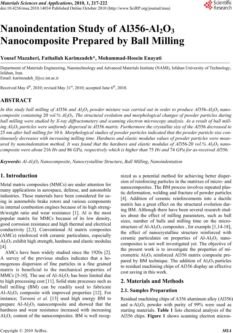 Materials Sciences and Applications, 2010, 1, 217-222 doi:10.4236/msa.2010.14034 Published Online October 2010 (http://www.SciRP.org/journal/msa) Copyright © 2010 SciRes. MSA Nanoindentation Study of Al356-Al2O3 Nanocomposite Prepared by Ball Milling Yousef Mazaheri, Fathallah Karimzadeh*, Mohammad-Hosein Enayati Department of Materials Engineering, Nanotechnology and Advanced Materials Institute (NAMI), Isfahan University of Technology, Isfahan, Iran. Email: karimzadeh_f@cc.iut.ac.ir Received May 4th, 2010; revised May 31st, 2010; accepted June 6th, 2010. ABSTRACT In this study ball milling of Al356 and Al2O3 powder mixture was carried out in order to produce Al356-Al2O3 nano- composite containing 20 vol.% Al2O3. The structural evolution and morphological changes of powder particles during ball milling were studied by X-ray diffractometery and scanning electron microscopy analysis. As a result of ball mill- ing Al2O3 particles were uniformly dispersed in Al356 matrix. Furthermore the crystallite size of the Al356 decreased to 25 nm after ball milling for 10 h. Morphological studies of powder particles indicated that the powder particle size con- tinuously decreases with increasing milling time. Hardness and elastic modulus values of powder particles were meas- ured by nanoindentation method. It was found that the hardness and elastic modulus of Al356-20 vol.% Al2O3 nano- composite were about 216 Hv and 86 GPa, respectively which is higher than 75 Hv and 74 GPa for as-received Al356. Keywords: Al-Al2O3 Nanocomposite, Nanocrystalline Structure, Ball Milling, Nanoindentation 1. Introduction Metal matrix composites (MMCs) are under attention for many applications in aerospace, defense, and automobile industries. These materials have been considered for us- ing in automobile brake rotors and various components in internal combustion engines because of its high streng- th/weight ratio and wear resistance [1]. Al is the most popular matrix for MMCs because of its low density, good corrosion resistance and high thermal and electrical conductivity [2,3]. Conventional Al matrix composites (AMCs) reinforced with ceramic particulates, especially Al2O3 exhibit high strength, hardness and elastic modulus [4]. AMCs have been widely studied since the 1920s [2]. A survey of the previous studies indicates that a ho- mogenous dispersion of fine particles in a fine grained matrix is beneficial to the mechanical properties of MMCs [5-10]. The use of Al-Al2O3 has been limited due to high processing cost [11]. Solid state processes such as ball milling (BM) can be readily used to fabricate Al-Al2O3 composite with improved properties [12]. For instance; Tavoosi et al. [13] used high energy BM to prepare Al-Al2O3 nanocomposite and showed that the hardness and wear resistance increased with increasing Al2O3 content of the nanocomposites. BM is well recog- nized as a potential method for achieving better disper- sion of reinforcing particles in the matrixes of micro- and nanocomposites. The BM process involves repeated plas- tic deformation, welding and fracture of powder particles [4]. Addition of ceramic reinforcements into a ductile matrix has a great effect on the structural evolution dur- ing BM. Although there have been several research stud- ies about the effect of milling parameters, such as ball sizes, number of balls and milling time on the micro- structure of Al-Al2O3 composites , for example [1,14-18], the effect of nanocrystalline structure reinforced with ceramic particulates on properties of Al-Al2O3 nano- composites is not well investigated yet. The objective of the present work is to investigate the properties of mi- crometric Al2O3 reinforced Al356 matrix composite pre- pared by BM technique. The addition of Al2O3 particles to residual machining chips of Al356 display an effective cost saving in this work. 2. Materials and Methods 2.1. Samples Preparation Residual machining chips of A356 aluminum alloy (Al356) and α-Al2O3 powder with purity of 99% were used as starting materials. Table 1 lists chemical analysis of the Al356 chips. Figure 1 shows scanning electron micros- 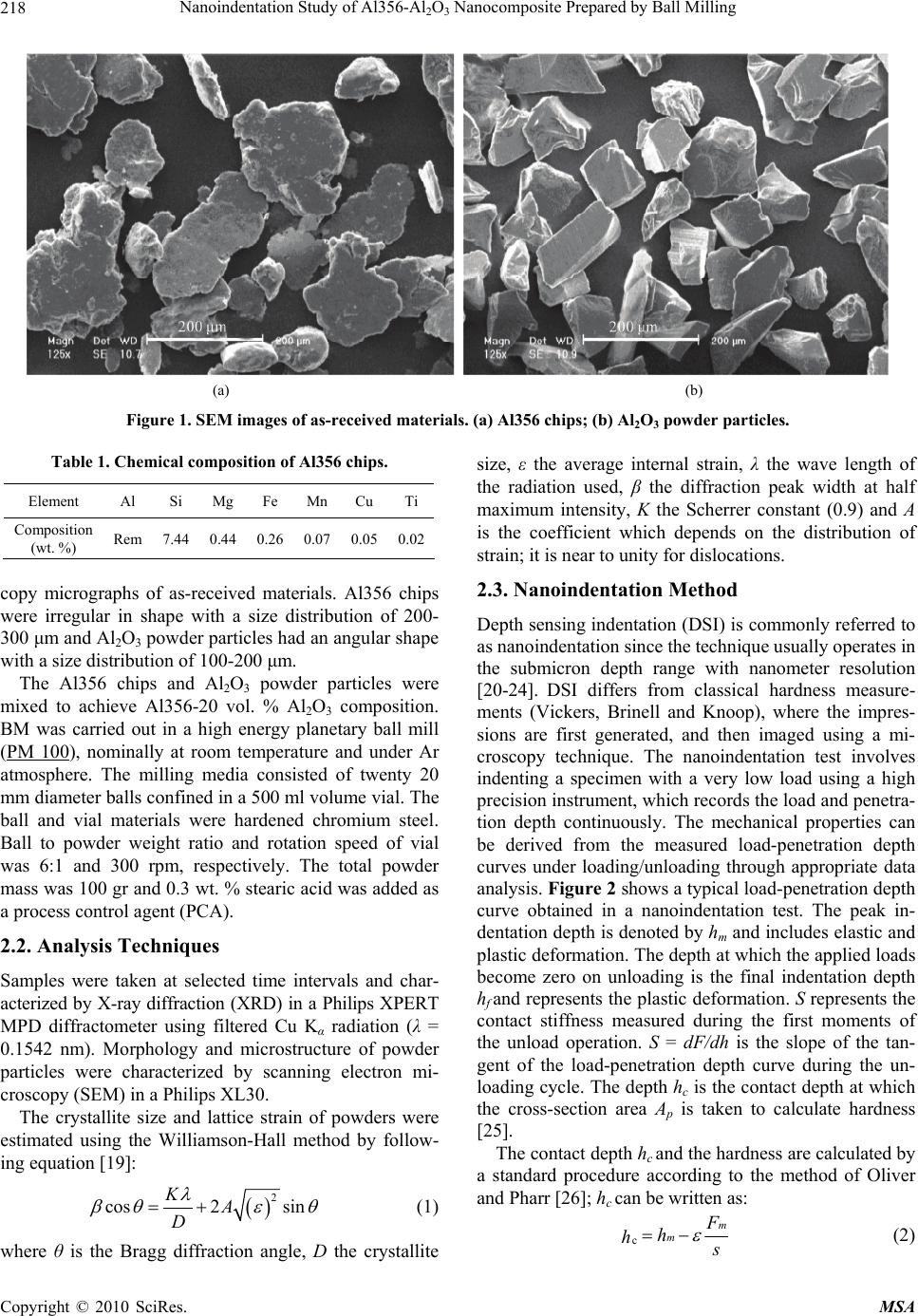 Nanoindentation Study of Al356-Al2O3 Nanocomposite Prepared by Ball Milling Copyright © 2010 SciRes. MSA 218 (a) (b) Figure 1. SEM images of as-received materials. (a) Al356 chips; (b) Al2O3 powder particles. Table 1. Chemical composition of Al356 chips. Element Al Si Mg Fe Mn Cu Ti Composition (wt. %) Rem 7.44 0.440.26 0.07 0.050.02 copy micrographs of as-received materials. Al356 chips were irregular in shape with a size distribution of 200- 300 μm and Al2O3 powder particles had an angular shape with a size distribution of 100-200 μm. The Al356 chips and Al2O3 powder particles were mixed to achieve Al356-20 vol. % Al2O3 composition. BM was carried out in a high energy planetary ball mill (PM 100), nominally at room temperature and under Ar atmosphere. The milling media consisted of twenty 20 mm diameter balls confined in a 500 ml volume vial. The ball and vial materials were hardened chromium steel. Ball to powder weight ratio and rotation speed of vial was 6:1 and 300 rpm, respectively. The total powder mass was 100 gr and 0.3 wt. % stearic acid was added as a process control agent (PCA). 2.2. Analysis Techniques Samples were taken at selected time intervals and char- acterized by X-ray diffraction (XRD) in a Philips XPERT MPD diffractometer using filtered Cu Kα radiation (λ = 0.1542 nm). Morphology and microstructure of powder particles were characterized by scanning electron mi- croscopy (SEM) in a Philips XL30. The crystallite size and lattice strain of powders were estimated using the Williamson-Hall method by follow- ing equation [19]: 2 cos2 sin KA D (1) where θ is the Bragg diffraction angle, D the crystallite size, ε the average internal strain, λ the wave length of the radiation used, β the diffraction peak width at half maximum intensity, K the Scherrer constant (0.9) and A is the coefficient which depends on the distribution of strain; it is near to unity for dislocations. 2.3. Nanoindentation Method Depth sensing indentation (DSI) is commonly referred to as nanoindentation since the technique usually operates in the submicron depth range with nanometer resolution [20-24]. DSI differs from classical hardness measure- ments (Vickers, Brinell and Knoop), where the impres- sions are first generated, and then imaged using a mi- croscopy technique. The nanoindentation test involves indenting a specimen with a very low load using a high precision instrument, which records the load and penetra- tion depth continuously. The mechanical properties can be derived from the measured load-penetration depth curves under loading/unloading through appropriate data analysis. Figure 2 shows a typical load-penetration depth curve obtained in a nanoindentation test. The peak in- dentation depth is denoted by hm and includes elastic and plastic deformation. The depth at which the applied loads become zero on unloading is the final indentation depth hf and represents the plastic deformation. S represents the contact stiffness measured during the first moments of the unload operation. S = dF/dh is the slope of the tan- gent of the load-penetration depth curve during the un- loading cycle. The depth hc is the contact depth at which the cross-section area Ap is taken to calculate hardness [25]. The contact depth hc and the hardness are calculated by a standard procedure according to the method of Oliver and Pharr [26]; hc can be written as: c m m F h h s (2) 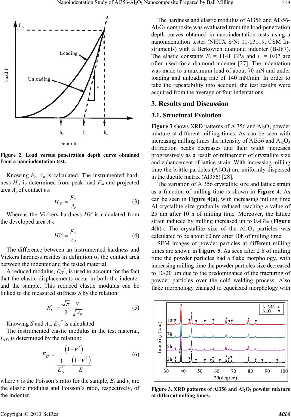 Nanoindentation Study of Al356-Al2O3 Nanocomposite Prepared by Ball Milling Copyright © 2010 SciRes. MSA 219 Figure 2. Load versus penetration depth curve obtained from a nanoindentation test. Knowing hc, Ap is calculated. The instrumented hard- ness HIT is determined from peak load Fm and projected area Ap of contact as: IT m p F H A (3) Whereas the Vickers hardness HV is calculated from the developed area Ad: m d F HV A (4) The difference between an instrumented hardness and Vickers hardness resides in definition of the contact area between the indenter and the tested material. A reduced modulus, EIT *, is used to account for the fact that the elastic displacements occur in both the indenter and the sample. This reduced elastic modulus can be linked to the measured stiffness S by the relation: * 2 IT p S E A (5) Knowing S and Ap, EIT * is calculated. The instrumented elastic modulus in the test material, EIT, is determined by the relation: 2 2 * 1 1 1 IT i i IT E E E (6) where ν is the Poisson’s ratio for the sample, Ei and νi are the elastic modulus and Poisson’s ratio, respectively, of the indenter. The hardness and elastic modulus of Al356 and Al356- Al2O3 composite was evaluated from the load-penetration depth curves obtained in nanoindentation tests using a nanoindentation tester (NHTX S/N: 01-03119, CSM In- struments) with a Berkovich diamond indenter (B-J87). The elastic constants Ei = 1141 GPa and νi = 0.07 are often used for a diamond indenter [27]. The indentation was made to a maximum load of about 70 mN and under loading and unloading rate of 140 mN/min. In order to take the repeatability into account, the test results were acquired from the average of four indentations. 3. Results and Discussion 3.1. Structural Evolution Figure 3 shows XRD patterns of Al356 and Al2O3 powder mixture at different milling times. As can be seen with increasing milling times the intensity of Al356 and Al2O3 diffraction peaks decreases and their width increases progressively as a result of refinement of crystallite size and enhancement of lattice strain. With increasing milling time the brittle particles (Al2O3) are uniformly dispersed in the ductile matrix (Al356) [28]. The variation of Al356 crystallite size and lattice strain as a function of milling time is shown in Figure 4. As can be seen in Figure 4(a), with increasing milling time Al crystallite size gradually redused reaching a value of 25 nm after 10 h of milling time. Moreover, the lattice strain induced by milling increased up to 0.43% (Figure 4(b)). The crystallite size of the Al2O3 particles was calculated to be about 60 nm after 10h of milling time. SEM images of powder particles at different milling times are shown in Figure 5. As seen after 2 h of milling time the powder particles had a flake morphology. with increasing milling time the powder particles size decreased to 10-20 μm due to the predominance of the fracturing of powder particles over the cold welding process. Also flake morphology changed to equeiaxed morphology with Figure 3. XRD patterns of Al356 and Al2O3 powder mixture at different milling times. 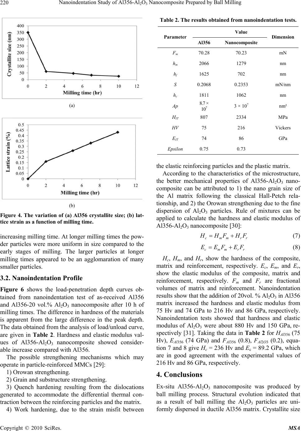 Nanoindentation Study of Al356-Al2O3 Nanocomposite Prepared by Ball Milling Copyright © 2010 SciRes. MSA 220 (a) (b) Figure 4. The variation of (a) Al356 crystallite size; (b) lat- tice strain as a function of milling time. increasing milling time. At longer milling times the pow- der particles were more uniform in size compared to the early stages of milling. The larger particles at longer milling times appeared to be an agglomaration of many smaller particles. 3.2. Nanoindentation Profile Figure 6 shows the load-penetration depth curves ob- tained from nanoindentation test of as-received Al356 and Al356-20 vol.% Al2O3 nanocomposite after 10 h of milling times. The difference in hardness of the materials is apparent from the large difference in the peak depth. The data obtained from the analysis of load/unload curve, are given in Table 2. Hardness and elastic modulus val- ues of Al356-Al2O3 nanocomposite showed consider- able increase compared with Al356. The possible strengthening mechanisms which may operate in particle-reinforced MMCs [29]: 1) Orowan strengthening. 2) Grain and substructure strengthening. 3) Quench hardening resulting from the dislocations generated to accommodate the differential thermal con- traction between the reinforcing particles and the matrix. 4) Work hardening, due to the strain misfit between Table 2. The results obtained from nanoindentation tests. Value Parameter Al356Nanocomposite Dimension Fm 70.28 70.23 mN hm 2066 1279 nm hf 1625 702 nm S 0.20680.2353 mN/nm hc 1811 1062 nm Ap 8.7 × 10⁷ 3 × 10⁷ nm² HIT 807 2334 MPa HV 75 216 Vickers EIT 74 86 GPa Epsilon 0.75 0.73 the elastic reinforcing particles and the plastic matrix. According to the characteristics of the microstructure, the better mechanical properties of Al356-Al2O3 nano- composite can be attributed to 1) the nano grain size of the Al matrix following the classical Hall-Petch rela- tionship, and 2) the Orowan strengthening due to the fine dispersion of Al2O3 particles. Rule of mixtures can be applied to calculate the hardness and elastic modulus of Al356-Al2O3 nanocomposite [30]: cmmrr H HF HF (7) cmmrr EEFEF (8) Hc, Hm, and Hr, show the hardness of the composite, matrix and reinforcement, respectively. Ec, Em, and Er, show the elastic modulus of the composite, matrix and reinforcement, respectively. Fm and Fr are fractional volumes of matrix and reinforcement. Nanoindentation results show that the addition of 20vol. % Al2O3 in Al356 matrix increased the hardness and elastic modulus from 75 Hv and 74 GPa to 216 Hv and 86 GPa, respectively. Nanoindentation tests showed that hardness and elastic modulus of Al2O3 were about 880 Hv and 150 GPa, re- spectively [31]. Taking the data in Table 2 for HAl356 (75 Hv), EAl356 (74 GPa) and FAl356 (0.8), FAl2O3 (0.2), equa- tion 7 and 8 give Hc = 236 Hv and Ec = 89.2 GPa, which are in good agreement with the experimental values of 216 Hv and 86 GPa, respectively. 4. Conclusions Ex-situ Al356-Al2O3 nanocomposite was produced by ball milling process. Structural evolution indicated that as a result of ball milling the Al2O3 particles are uni- formly dispersed in ductile Al356 matrix. Crystallite size 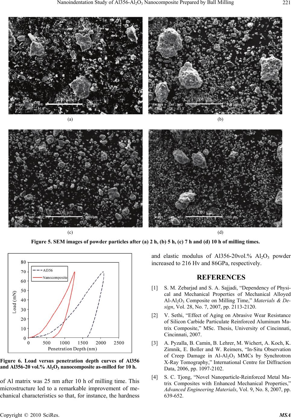 Nanoindentation Study of Al356-Al2O3 Nanocomposite Prepared by Ball Milling Copyright © 2010 SciRes. MSA 221 (a) (b) (c) (d) Figure 5. SEM images of powder particles after (a) 2 h, (b) 5 h, (c) 7 h and (d) 10 h of milling times. Figure 6. Load versus penetration depth curves of Al356 and Al356-20 vol.% Al2O3 nanocomposite as-milled for 10 h. of Al matrix was 25 nm after 10 h of milling time. This microstructure led to a remarkable improvement of me- chanical characteristics so that, for instance, the hardness and elastic modulus of Al356-20vol.% Al2O3 powder increased to 216 Hv and 86GPa, respectively. REFERENCES [1] S. M. Zebarjad and S. A. Sajjadi, “Dependency of Physi- cal and Mechanical Properties of Mechanical Alloyed Al-Al2O3 Composite on Milling Time,” Materials & De- sign, Vol. 28, No. 7, 2007, pp. 2113-2120. [2] V. Sethi, “Effect of Aging on Abrasive Wear Resistance of Silicon Carbide Particulate Reinforced Aluminum Ma- trix Composite,” MSc. Thesis, University of Cincinnati, Cincinnati, 2007. [3] A. Pyzalla, B. Camin, B. Lehrer, M. Wichert, A. Koch, K. Zimnik, E. Boller and W. Reimers, “In-Situ Observation of Creep Damage in Al-Al2O3 MMCs by Synchrotron X-Ray Tomography,” International Centre for Diffraction Data, 2006, pp. 1097-2102. [4] S. C. Tjong, “Novel Nanoparticle-Reinforced Metal Ma- trix Composites with Enhanced Mechanical Properties,” Advanced Engineering Materials, Vol. 9, No. 8, 2007, pp. 639-652. 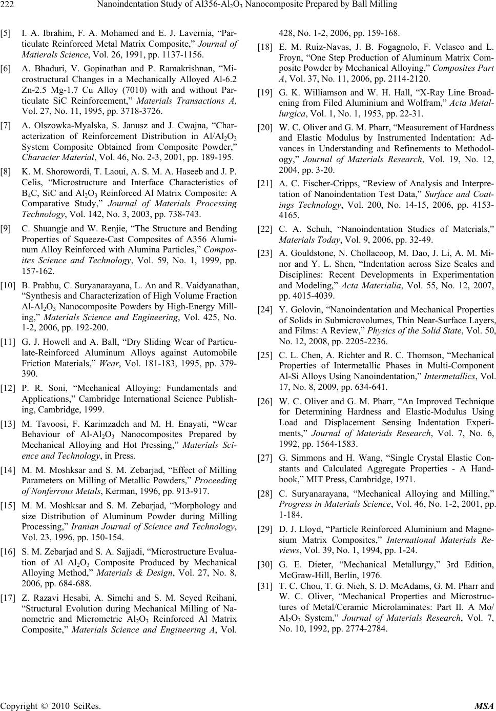 Nanoindentation Study of Al356-Al2O3 Nanocomposite Prepared by Ball Milling Copyright © 2010 SciRes. MSA 222 [5] I. A. Ibrahim, F. A. Mohamed and E. J. Lavernia, “Par- ticulate Reinforced Metal Matrix Composite,” Journal of Matierals Science, Vol. 26, 1991, pp. 1137-1156. [6] A. Bhaduri, V. Gopinathan and P. Ramakrishnan, “Mi- crostructural Changes in a Mechanically Alloyed Al-6.2 Zn-2.5 Mg-1.7 Cu Alloy (7010) with and without Par- ticulate SiC Reinforcement,” Materials Transactions A, Vol. 27, No. 11, 1995, pp. 3718-3726. [7] A. Olszowka-Myalska, S. Janusz and J. Cwajna, “Char- acterization of Reinforcement Distribution in Al/Al2O3 System Composite Obtained from Composite Powder,” Character Material, Vol. 46, No. 2-3, 2001, pp. 189-195. [8] K. M. Shorowordi, T. Laoui, A. S. M. A. Haseeb and J. P. Celis, “Microstructure and Interface Characteristics of B4C, SiC and Al2O3 Reinforced Al Matrix Composite: A Comparative Study,” Journal of Materials Processing Technology, Vol. 142, No. 3, 2003, pp. 738-743. [9] C. Shuangje and W. Renjie, “The Structure and Bending Properties of Squeeze-Cast Composites of A356 Alumi- num Alloy Reinforced with Alumina Particles,” Compos- ites Science and Technology, Vol. 59, No. 1, 1999, pp. 157-162. [10] B. Prabhu, C. Suryanarayana, L. An and R. Vaidyanathan, “Synthesis and Characterization of High Volume Fraction Al-Al2O3 Nanocomposite Powders by High-Energy Mill- ing,” Materials Science and Engineering, Vol. 425, No. 1-2, 2006, pp. 192-200. [11] G. J. Howell and A. Ball, “Dry Sliding Wear of Particu- late-Reinforced Aluminum Alloys against Automobile Friction Materials,” Wear, Vol. 181-183, 1995, pp. 379- 390. [12] P. R. Soni, “Mechanical Alloying: Fundamentals and Applications,” Cambridge International Science Publish- ing, Cambridge, 1999. [13] M. Tavoosi, F. Karimzadeh and M. H. Enayati, “Wear Behaviour of Al-Al2O3 Nanocomposites Prepared by Mechanical Alloying and Hot Pressing,” Materials Sci- ence and Technology, in Press. [14] M. M. Moshksar and S. M. Zebarjad, “Effect of Milling Parameters on Milling of Metallic Powders,” Proceeding of Nonferrous Metals, Kerman, 1996, pp. 913-917. [15] M. M. Moshksar and S. M. Zebarjad, “Morphology and size Distribution of Aluminum Powder during Milling Processing,” Iranian Journal of Science and Technology, Vol. 23, 1996, pp. 150-154. [16] S. M. Zebarjad and S. A. Sajjadi, “Microstructure Evalua- tion of Al–Al2O3 Composite Produced by Mechanical Alloying Method,” Materials & Design, Vol. 27, No. 8, 2006, pp. 684-688. [17] Z. Razavi Hesabi, A. Simchi and S. M. Seyed Reihani, “Structural Evolution during Mechanical Milling of Na- nometric and Micrometric Al2O3 Reinforced Al Matrix Composite,” Materials Science and Engineering A, Vol. 428, No. 1-2, 2006, pp. 159-168. [18] E. M. Ruiz-Navas, J. B. Fogagnolo, F. Velasco and L. Froyn, “One Step Production of Aluminum Matrix Com- posite Powder by Mechanical Alloying,” Composites Part A, Vol. 37, No. 11, 2006, pp. 2114-2120. [19] G. K. Williamson and W. H. Hall, “X-Ray Line Broad- ening from Filed Aluminium and Wolfram,” Acta Metal- lurgica, Vol. 1, No. 1, 1953, pp. 22-31. [20] W. C. Oliver and G. M. Pharr, “Measurement of Hardness and Elastic Modulus by Instrumented Indentation: Ad- vances in Understanding and Refinements to Methodol- ogy,” Journal of Materials Research, Vol. 19, No. 12, 2004, pp. 3-20. [21] A. C. Fischer-Cripps, “Review of Analysis and Interpre- tation of Nanoindentation Test Data,” Surface and Coat- ings Technology, Vol. 200, No. 14-15, 2006, pp. 4153- 4165. [22] C. A. Schuh, “Nanoindentation Studies of Materials,” Materials Today, Vol. 9, 2006, pp. 32-49. [23] A. Gouldstone, N. Chollacoop, M. Dao, J. Li, A. M. Mi- nor and Y. L. Shen, “Indentation across Size Scales and Disciplines: Recent Developments in Experimentation and Modeling,” Acta Materialia, Vol. 55, No. 12, 2007, pp. 4015-4039. [24] Y. Golovin, “Nanoindentation and Mechanical Properties of Solids in Submicrovolumes, Thin Near-Surface Layers, and Films: A Review,” Physics of the Solid State, Vol. 50, No. 12, 2008, pp. 2205-2236. [25] C. L. Chen, A. Richter and R. C. Thomson, “Mechanical Properties of Intermetallic Phases in Multi-Component Al-Si Alloys Using Nanoindentation,” Intermetallics, Vol. 17, No. 8, 2009, pp. 634-641. [26] W. C. Oliver and G. M. Pharr, “An Improved Technique for Determining Hardness and Elastic-Modulus Using Load and Displacement Sensing Indentation Experi- ments,” Journal of Materials Research, Vol. 7, No. 6, 1992, pp. 1564-1583. [27] G. Simmons and H. Wang, “Single Crystal Elastic Con- stants and Calculated Aggregate Properties - A Hand- book,” MIT Press, Cambridge, 1971. [28] C. Suryanarayana, “Mechanical Alloying and Milling,” Progress in Materials Science, Vol. 46, No. 1-2, 2001, pp. 1-184. [29] D. J. Lloyd, “Particle Reinforced Aluminium and Magne- sium Matrix Composites,” International Materials Re- views, Vol. 39, No. 1, 1994, pp. 1-24. [30] G. E. Dieter, “Mechanical Metallurgy,” 3rd Edition, McGraw-Hill, Berlin, 1976. [31] T. C. Chou, T. G. Nieh, S. D. McAdams, G. M. Pharr and W. C. Oliver, “Mechanical Properties and Microstruc- tures of Metal/Ceramic Microlaminates: Part II. A Mo/ Al2O3 System,” Journal of Materials Research, Vol. 7, No. 10, 1992, pp. 2774-2784. |