Paper Menu >>
Journal Menu >>
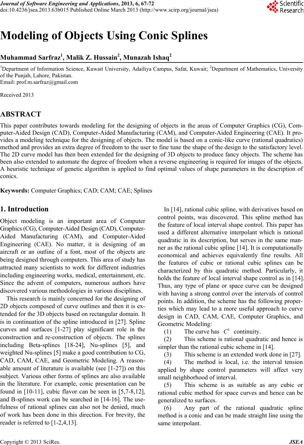 Journal of Software Engineering and Applications, 2013, 6, 67-72 doi:10.4236/jsea.2013.63b015 Published Online March 2013 (http://www.scirp.org/journal/jsea) Copyright © 2013 SciRes. JSEA 67 Modeling of Objects Using Conic Splines Muhammad Sarfraz1, Malik Z. Hussain2, Munazah Ishaq2 1Department of Information Science, Kuwait University, Adailiya Campus, Safat, Kuwait; 2Department of Mathematics, University of the Punjab, Lahore, Pakistan. Email: prof.m.sarfraz@gmail.com Received 2013 ABSTRACT This paper contributes towards modeling for the designing of objects in the areas of Computer Graphics (CG), Com- puter-Aided Design (CAD), Computer-Aided Manufacturing (CAM), and Computer-Aided Engineering (CAE). It pro- vides a modeling technique for the designing of objects. The model is based on a conic-like curve (rational quadratics) method and provides an extra degree of freedom to the user to fine tune the shape of the design to the satisfactory level. The 2D curve model has then been extended for the designing of 3D objects to produce fancy objects. The scheme has been also extended to automate the degree of freedom when a reverse engineering is required for images of the objects. A heuristic technique of genetic algorithm is applied to find optimal values of shape parameters in the description of conics. Keywords: Computer Graphics; CAD; CAM; CAE; Splines 1. Introduction Object modeling is an important area of Computer Graphics (CG), Computer-Aided Design (CAD), Computer- Aided Manufacturing (CAM), and Computer-Aided Engineering (CAE). No matter, it is designing of an aircraft or an outline of a font, most of the objects are being designed through computers. This area of study has attracted many scientists to work for different industries including engineering works, medical, entertainment, etc. Since the advent of computers, numerous authors have discovered various methodologies in various disciplines. This research is mainly concerned for the designing of 2D objects composed of curve outlines and then it is ex- tended for the 3D objects based on rectangular domain. It is in continuatio n of the spline introdu ced in [27]. Spline curves and surfaces [1-27] play significant role in the construction and re-construction of objects. The splines including Beta-splines [18-24], Nu-splines [5], and weighted Nu-splines [5] make a good contribution to CG, CAD, CAM, CAE, and Geometric Modeling. A reason- able amount of literature is available (see [1-27]) on this subject. Various other forms of splines are also available in the literature. For example, conic presentation can be found in [10-11], cubic flavor can be seen in [5,7-8,12], and B-splines work can be searched in [14-16]. The use- fulness of rational splines can also not be denied, much of work has been done in this direction. For brevity, the reader is referred to [1-2,4,13]. In [14], rational cubic spline, with derivatives based on control points, was discovered. This spline method has the feature of local interval shape control. This paper has used a different alternative interpolant which is rational quadratic in its description, but serves in the same man- ner as the rational cubic spline [14]. It is computationally economical and achieves equivalently fine results. All the features of cubic or rational cubic splines can be characterized by this quadratic method. Particularly, it holds the feature of local interval shape control as in [14]. Thus, any type of plane or space curve can be designed with having a strong control over the intervals of control points. In addition, the scheme has the following proper- ties which may lead to a more useful approach to curve design in CAD, CAM, CAE, Computer Graphics, and Geometric Modeling: (1) The curve has 1 C continuity. (2) This scheme is rational quadratic and hence is simpler than the rational cubic scheme in [14]. (3) This scheme is an extended work done in [27]. (4) The method is local, i.e. the interval tension applied by shape control parameters will affect very small neighborhood of interval. (5) This scheme is as suitable as any cubic or rational cubic method for space curves and hence can be generalized to surfaces. (6) Any part of the rational quadratic spline method is a conic and can be made straight line using the same interpolant. 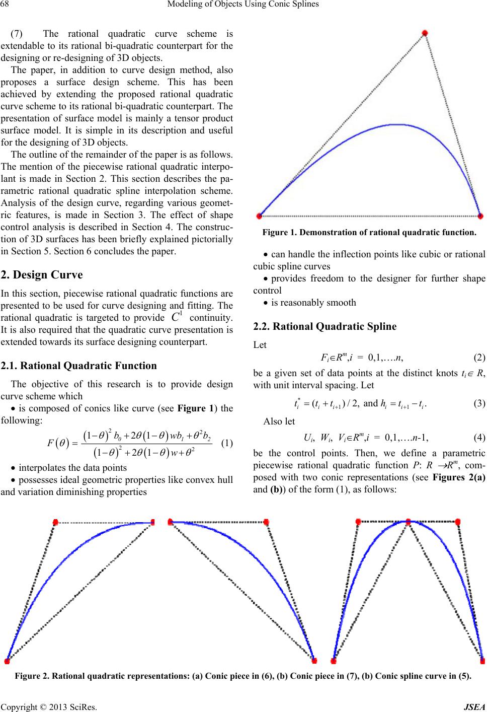 Modeling of Objects Using Conic Splines Copyright © 2013 SciRes. JSEA 68 (7) The rational quadratic curve scheme is extendable to its rational bi-quadratic counterpart for the designin g or re-design ing of 3D objects. The paper, in addition to curve design method, also proposes a surface design scheme. This has been achieved by extending the proposed rational quadratic curve scheme to its rational bi-quadratic co unterpart. The presentation of surface model is mainly a tensor product surface model. It is simple in its description and useful for the designing of 3D objects. The outline of the remainder of the pa per is as follo ws. The mention of the piecewise rational quadratic interpo- lant is made in Section 2. This section describes the pa- rametric rational quadratic spline interpolation scheme. Analysis of the design curve, regarding various geomet- ric features, is made in Section 3. The effect of shape control analysis is described in Section 4. The construc- tion of 3D surfaces has been briefly explained pictorially in Section 5. Section 6 concludes the paper. 2. Design Curve In this section, piecewise rational quadratic func tions are presented to be used for curve designing and fitting. The rational quadratic is targeted to provide 1 C continuity. It is also required that the quadratic curve presentation is extended towards its surface designing counterpart. 2.1. Rational Quadratic Function The objective of this research is to provide design curve scheme which is composed of conics like curve (see Figure 1) the following: 22 22 121 121 012 bwbb Fw (1) interpolates the data points possesses ideal geometric properties like convex hull and variation diminishing properties Figure 1. Demonstration of rational quadratic function. can handle the inflection points like cubic or rational cubic spline curves provides freedom to the designer for further shape control is reasonably smooth 2.2. Rational Quadratic Spline Let FiRm,i = 0,1,….n, (2) be a given set of data points at the distinct knots ti R, with unit interval sp acing. Let *11 ()/2, and . iii iii ttt htt (3) Also let Ui, Wi, ViRm,i = 0,1,….n-1, (4) be the control points. Then, we define a parametric piecewise rational quadratic function P: R Rm, com- posed with two conic representations (see Figures 2(a) and (b)) of the form (1), as follows: Figure 2. Rational quadratic representations: (a) Conic piece in (6), (b) Conic piece in (7), (b) Conic spline curve in (5). 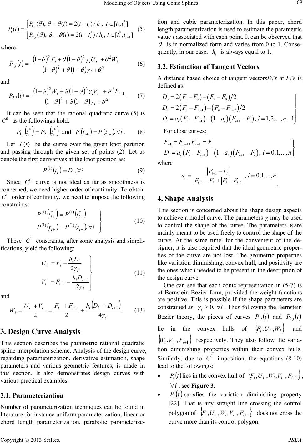 Modeling of Objects Using Conic Splines Copyright © 2013 SciRes. JSEA 69 * 1, ** 2, 1 (),()2()/,[, ], () (),()2()/,[,] iiiii i iiiii Pttthttt Pt Pttthttt (5) where 2 2 2 22 ,1 11 11 i i i ii iWUF tP (6) and 2 21 2 22 ,2 11 11 i i i ii iFVW tP (7) It can be seen that the rational quadratic curve (5) is 0 C as the followings hold: * ,2 * ,1 iiii tPtP and itPtP iiii ,. (8) Let ()Pt be the curve over the given knot partition and passing through the given set of points (2). Let us denote the first derivatives at the knot position as: iDtP ii , )1( (9) Since 0 C curve is not ideal as far as smoothness is concerned, we need higher order of continuity. To obtain 1 C order of continuity, we need to impose the following constraints: itPtP tPtP ii ii , )1()1( * )1( * )1( (10) These 1 C constraints, after some analysis and simpli- fications, yield the following: i ii ii i ii i i Dh FV Dh FU 2 2 1 1 (11) and i i i i i i ii iDDhFF VU W 422 11 (13) 3. Design Curve Analysis This section describes the parametric rational quadratic spline interpolation scheme. Analysis of the design curve, regarding parameterization, derivative estimation, shape parameters and various geometric features, is made in this section. It also demonstrates design curves with various practical examples. 3.1. Parameterization Number of parameterization techniques can be found in literature for instance uniform parameterization, linear or chord length parameterization, parabolic parameterize- tion and cubic parameterization. In this paper, chord length parameterization is used to estimate the parametric value t associated with each point. It can be observed that i is in normalized form and varies from 0 to 1. Conse- quently, in our case, i h is always equal to 1. 3.2. Estimation of Tangent Vectors A distance based choice of tangent vectorsDi’s at Fi’s is defined as: 01020 12 11 22 22 1,1,2,..., 1 nnnnn iiiiii i DFFFF DFFFF DaFFaF Fin For close curves: 1111 11 , 1, 0,1,..., nn iiiiiii FFF F D aF FaFFin where 1 11 , 0,1,..., ii i iiii FF ain FFFF . 4. Shape Analysis This section is concerned about the shape design aspects to achieve a model curve. The parameters i may be used to control the shape of the curve. The parameters i are mainly meant to be used freely to control the shape of the curve. At the same time, for the convenient of the de- signer, it is also required that the ideal geometric proper- ties of the curve are not lost. The geometric properties like variation diminishing, convex hull, and positivity are the ones which needed to be present in the description of the design curve. One can see that each conic representation in (5-7) is of Bernstein Bezier form, provided the weight functions are positive. This is possible if the shape parameters are constrained as i i ,0 . Thus following the Bernstein Bezier theory, the pieces of curves tP i,1 and tP i,2 lie in the convex hulls of i i iWUF ,, and 1 ,, i i iFVW respectively. They also follow the varia- tion diminishing properties within their convex hulls. Similarly, due to 1 C imposition, the equations (8-10) lead to the followings: tPilies in the convex hull of 1 ,,,, i i i i iFVWUF , i , see Figure 3. tPisatisfies the variation diminishing property [22]. That is any straight line crossing the control polygon of 1 ,,,, i i i i iFVWUF does not cross the curve more than its control polygon. 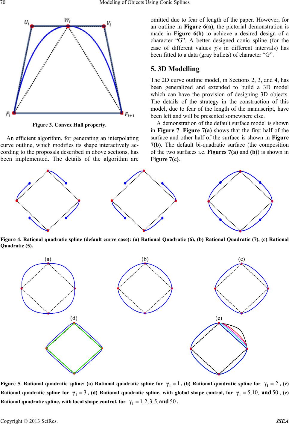 Modeling of Objects Using Conic Splines Copyright © 2013 SciRes. JSEA 70 Figure 3. Convex Hull property. An efficient algorithm, for generating an interpolating curve outline, which modifies its shape interactively ac- cording to the proposals described in above sections, has been implemented. The details of the algorithm are omitted due to fear of length of the paper. However, for an outline in Figure 6(a), the pictorial demonstration is made in Figure 6(b) to achieve a desired design of a character “G”. A better designed conic spline (for the case of different values i's in different intervals) has been fitted to a data (gray bullets) of character “G”. 5. 3D Modelling The 2D curve outline model, in Sections 2, 3, and 4, has been generalized and extended to build a 3D model which can have the provision of designing 3D objects. The details of the strategy in the construction of this model, due to fear of the length of the manuscript, have been left and will be presented somewhere else. A demonstration of the default surface model is shown in Figure 7. Figure 7(a) shows that the first half of the surface and other half of the surface is shown in Figure 7(b). The default bi-quadratic surface (the composition of the two surfaces i.e. Figures 7(a) and (b)) is shown in Figure 7(c). Figure 4. Rational quadratic spline (default curve case): (a) Rational Quadratic (6), (b) Rational Quadratic (7), (c) Rational Quadratic (5). (a) (b) (c) (d) (e) Figure 5. Rational quadratic spline: (a) Rational quadratic spline for 1 i γ, (b) Rational quadratic spline for 2 i γ, (c) Rational quadratic spline for 3 i γ, (d) Rational quadratic spline, with global shape control, for 5,10, 50 i γand , (e) Rational quadratic spline, with local shape control, for 1, 2, 3, 5,50 i γand .  Modeling of Objects Using Conic Splines Copyright © 2013 SciRes. JSEA 71 Some more pictorial demonstrations are made as fol- lows. A wire frame model, with u-lines is constructed, as the first step in the Figure 8(a) of a bottle. Secondly, uv-lines are drawn to provide a complete wire frame model (see Figure 8(b)). Thirdly, visibility detection method is used to provide a realistic view of the picture (see Figure 8(c)). Another feature built in the 3D model is the local shape control like in the 2D models demon- strated in Section 3.3. This feature can be seen in Fig- ures 8(a-c) at the neck of the bottle showing interval tension. Another pictorial example of a vase is shown in Fig- ure 9. The wire frame model is shown in Figure 9(a) and its shaded model is demonstrated in Figure 9(b). A variety of shape control has been applied at different places to achieve the shown model. (a) (b) Figure 6. Rational quadratic spline: (a) Rational quadratic spline for 2 i γ, (b) Rational quadratic spline for varying values of i γ in different intervals. (a) (b) (c) Figure 7. Rational bi-quadratic spline interpolant: (a) Ra- tional bi-quadratic 1.(b) Rational bi-quadratic 2, (c) Ra- tional bi-quadratic. (a) (b) (c) Figure 8. Rational bi-quadratic spline for the design of a bottle: (a) A wire frame model, with u-lines, (b) A wire frame model with uv-lines, (c) A wire frame model with uv-lines and hidden surface removal. (a) (b) Figure 5. A bi-conic Spline model for a Vase: left one is a wire-frame model, right one is the shaded model. 6. Conclusion and Future Work A shape controlling piecewise rational quadratic interpo- lation scheme, to design 2D and 3D objects, has been proposed. The scheme offers a possible and feasible way in which the shape of the objects may be altered by the user. Such a scheme can make a useful addition to an interactive design package in a CG/CAD/CAM/CAE environment. It provides the users complete control over the curve segments and surface patches to modify the shape to achieve a model object. The changes will be local and that the shape will change in a stable manner. The scheme is quite simple, easy to implement and computationally economical as compared to its cubic and bi-cubic counter parts. The authors are thinking to extend the scheme for various applications including font de- signing, image outline capture, modeling animation paths, and others. 7. Acknowledgements This work was supported by Kuwait University. REFERENCES [1] J. A. Gregory, and P.K. Yuen, An arbitrary mesh network scheme using rational splines, in: T. Lyche and L.L. Schumaker (eds.), Mathematical Methods in Computer Aided Geometric Design II, Academic Press, 321-329, 1992. [2] J. A. Gregory, M. Sarfraz, and P.K. Yuen, Curves and Surfaces for Computer Aided Design using Rational Cu- bic Splines, Engineering with Computers, 11:94-102, 1995. [3] J. Hoschek, Circular splines, Computer-Aided Design, 24:611-618, 1992. [4] M. Sarfraz, M. Hussain, and Z. Habib, Local convexity preserving rational cubic spline curves, Proceedings of  Modeling of Objects Using Conic Splines Copyright © 2013 SciRes. JSEA 72 IEEE Conference on Information Visualization, IV'97, London, 211-218, 1997. [5] T. A. Foley and H. S. Ely, Interpolation with interval and point tension controls using cubic weighted Nu-splines, ACM Transactions on Mathematical Software, 13(1): 68-96, 1987. [6] L. Piegl, and W. Tiller, The NURBS Book, Springer, 1995. [7] Sarfraz, M., Al-Mulhem, M., Al-Ghamdi, J., and Hussain, A., Quadratic Representation to a C1 Rational Cubic Spline with Interval Shape Control, Proc International Conference on Imaging Science, Systems, and Technol- ogy (CISST'98), USA, 322-329, 1998. [8] J. S. Kouh, and S. W. Chau, Computer-aided geometric design and panel generation for hull forms based on ra- tional cubic Bezier curves, , Computer Aided Geometric Design, 10:537-549, 1993. [9] V. Pratt, Techniques for conic splines, Proceedings of SIGGRAPH, 151-159, 1985. [10] T. Pavlidis, Curve fitting with conic splines, ACM Transactions on Graphics, 1-31, 1983. [11] M. Plass and Maureen Stone, Curve-fitting with Piece- wise Parametric Cubics, Computer Graphics, 17(3): 229-239, 1983. [12] G. Nielson, Rectangular Nu-splines, IEEE Computer Graphics and Applications, 35-40, 1986. [13] J. A. Gregory and M. Sarfraz, A rational cubic spline with tension, Computer Aided Geometric Design, 7:1-13, 1990. [14] T. A. Foley and H. S. Ely, Interpolation with interval and point tension controls using cubic weighted Nu-splines, ACM Transactions on Mathematical Software, 13(1): 68-96, 1987. [15] M. Paluszny and R. Patterson, A family of tangent conti- nous cubic algebraic splines, ACM Transactions on Graphics, 12(3):209-232, 1993. [16] J. C. Beatty R. Bartels and K. S. Booth, Experimental comparision of splines using the shape-matching para- digm, ACM Transactions on Graphics, 12(3):179-208, 1993. [17] B. A. Barsky, Computer Graphics and Geometric Mod- eling using Beta-Splines, Springer-verlag, 1986, Tokyo. [18] T. N. T. Goodman, Properties of Beta-Splines, Journal of Approximation Theory, 44(2):132-153, 1985. [19] B. Barsky and J. Bea tty, Lo cal contr ol of bia s and tens ion in Beta-Splines, ACM Transactions on Graphics, 2(2):73-77, 1983. [20] D. Joe, Multiple knot and rational cubic beta-splines, ACM Transactions on Graphics, 8(2):100-120, 1989. [21] T. N. T. Goodman and K. Unsworth, Manipulating shape and producing geometric continuity in beta-splines curves, IEEE Computer Graphics and Applications, 6(2):50-56, 1986. [22] M. Sarfraz, Interactive curve modeling with applications to computer graphics, vision and image processing. Springer, 2008. [23] M. Sarfraz, M. Hussain, M. Irshad, and A. Khalid, Ap- proximating boundary of bitmap characters using genetic algorithm, Seventh International Conference on Com- puter Graphics, Imaging and Visualization (CGIV'10), 2010, 671-680. [24] Z.R. Yahya, A.R.M Piah and A.A. Majid, G1 continuity conics for curve fitting using particle swarm optimization, E. Banissi et al. (Eds.) 15th International Conference on Information Visualization,. IV, 2011, 497-501. [25] M. Sarfraz, S. Raza and M. Baig, Capturing image out- lines using soft computing approach with conic splines, International Conference of Soft Computing and Pattern Recognition, 2009, 289-294. [26] P. Priza, S. M. Shamsuddin and A. Ali, Differential evo- lution optimization for Bezier curve fitting, Seventh In- ternational Conference on Computer Graphics, Imaging and Visualization, 2010, 68-72. [27] M. Sarfraz, M. Al-Mulhem, J. Al-Ghamdi, and A. M. Hussain, Representing a C1 Rational Quadratic Spline with Interval Shape Control, Proceedings of International Conference on Imaging Science, Systems, and Technol- ogy (CISST'98), Las Vegas, Nevada, USA, CSREA Press, USA, 322-329, 1998. |