Journal of Software Engineering and Applications, 2013, 6, 147-155
http://dx.doi.org/10.4236/jsea.2013.63019 Published Online March 2013 (http://www.scirp.org/journal/jsea) 147
Toolchain Based on MDE for the Transformation of AADL
Models to Timed Automata Models
Mohamed El-Kamel Hamdane1, Allaoui Chaoui2, Martin Strecker3
1Department of Computer Science, Normal High School of Constantine, Constantine, Algeria; 2Department of Computer Science,
Mentouri University of Constantine, Constantine, Algeria; 3Institute de Recherche en Informatique de Toulouse, Paul Sabatier Uni-
versity, Toulouse, France.
Email: hamdane.med@gmail.com, a_chaoui2011@ yahoo.com, martin.strecker@irit.fr
Received December 8th, 2012; revised January 11th, 2013; accepted January 20th, 2013
ABSTRACT
In this work, we propose an approach for the verification of the AADL architecture. This approach is based on Model
Driven Engineering (MDE) and assisted by a toolchain. Indeed, we define a source meta-model for AADL and a target
meta-model for the timed automata formalism; we define a transformation process in two steps: the first is a Model2
Model transformation which takes an AADL Model and produces the corresponding timed automata model. The second
transformation is a Model2 Text transformation which takes a timed automata model and generates a text in ta-format
code. This code is accepted by the Uppaal toolbox. A case study has been developed to show the feasibility and validity
of the proposed appro ach.
Keywords: AADL; Timed Automata; Transformation; Verification; Uppaal
1. Introduction
The MDE [1] Model Driven Engineering approach pro-
vided through its concepts a complete framework to de-
velop a complex system. In essence, the MDE approach
allows several levels of abstraction for modeling com-
plex systems and thus provides most automation in their
development task. The embedded system is a type of
complex system which the MDE approach can be used.
The AADL [2] (Architecture Analysis and Design
Language) language is an ADL (Architecture Description
Language) specifically for real-time embedded systems.
In this type of system, the temporal properties take an
important place in development [3]. The AADL language
focuses on the architectural aspects: it allows descrip-
tion of components and their connections, but does not
deal with their behavior implementation or semantics of
the data handled. This requires a step of evaluation of the
possible behaviors of the system in order to ensure that
the implementation of such architecture meet its specifi-
cations. Hence, the need to adopt a formal analysis tech-
nique to verify the behavior of AADL components and
their interactions.
In our work, we chose the formalism of timed auto-
mata [4] as target formalism for the verification of AADL
models. This is justified by their ability to represent
temporal constrain ts [4]. In add ition, these models have a
great capacity for analysis [5]. Indeed, several verifica-
tion tools have been developed around this formalism as
UPPAAL [6] and KRONOS [7], etc. The purpose of the
toolchain is to simulate the behavior of an AADL archi-
tecture and verification of properties using the Uppaal
toolbox.
This paper is organized as follows: Section 2 gives an
overview of the AADL language. In Section 3 we de-
scribe in detail the proposed approach. Nex t, in Section 4
we illustrate our approach with a case study. In Sectio n 5,
we present a brief related work. Finally, we close the
paper with conclu sion and futur e works.
2. AADL Language
The AADL [2] was designed as a language to facilitate
the design and analysis of complex systems, critical and
real-time such as aeronautical, automotive and aerospace.
It is derived from the language Meta-H developed by
Honeywell and is standardized by the SAE (Society of
Automotive Engineers) [2].
AADL has many advantages that justify its growing
interest in the embedded industry. This language was
designed to be extensible, using either properties or by
defining annexes that can be extended according to the
specific design. The standard AADL can be expressed in
different syntaxes: text format, XML format and graphi-
cal presentation. Through its various syntaxes, AADL
can be used by many tools, whether graphical or not.
Copyright © 2013 SciRes. JSEA
Toolchain Based on MDE for the Transformation of AADL Models to Timed Automata Models
148
Finally through proposed standard precise execution se-
mantics, it allows to define the behavior system modeled
by AADL, and a semantic basis for common analysis
tools.
The listing of Figure 1 shows the behavior of a soft-
ware component thread named Producer. This thread is
periodic with a period of 10 ms. It contains a behavioral
annex, which defines a variable C of type integer with
initial value C = 0. The initial state of the thread is S0
from which it can move to state S1 through interaction on
port DataSource. During this transition the value of C is
increment.
3. From AADL Models to Timed Automata
Models
The aim of the approach is to transform AADL models to
an analysis model timed automata supported by the Up-
paal model checker (target model).The approach we have
implemented follows strictly the approach of Models
Driven Engineering [8].
The proposed approach consists of three phases. The
first 1st phase: we define for each model (source and
target) theirs meta-model. In the second phase we define
a transformation process in two steps:
The first step consists in taking an AADL models and
transform it (Model2 Model transformation) into a
timed automata models (intermediate model). This
formalism is considered as a formal model for de-
scribing real-time systems. They provide a formal
support to their analysis. Furthermore, there are many
model checker tools around this formalism.
The second step in this transformation process is a
Model2 Text transformation. It consists in taking the
timed automata models produced by the previous
phase and translate it into a ta-format [6] description
(the input format of the Uppaal toolbox).
In the last phase consists to open the description gen-
erated by the Uppaal model checker and begin a verifi-
cation task in order to evaluate some properties such as:
deadlock, reachability, liveness, ...etc.
An overview of the proposed approach is given in Fig-
ure 2.
A: The first phase: Meta-Modelisation
The source and target meta-model are represented in
Ecore format within EMF [8] (Eclipse Modeling Fram-
work).
Meta-Model of AADL
AADL has a great capacity of expression. There are,
indeed, a great number of component types which can be
used to build hierarchical models. As an indication, the
AADL meta-model contains 254 classes including 56 ab-
stract classes. In order to minimize the complexity of the
AADL language; the meta-model proposed respects the
following hypotheses:
1) The proposed meta-model supports only software
components.
Figure 1. Example of AADL software component thread
with behavioral annex.
Source Model
1st Transformation
M2M
Timed Automata
Models
ADDL
Models Uppaal Model
2nd Transformation
M2T
Intermediate ModelTarget Model
Meta-Model
AADL Meta-Model
Timed Automata
1
3
2
4
Source Model
1st Transformation
M2M
1st Transformation
M2M
Timed Automata
Models
ADDL
Models Uppaal Model
2nd Transformation
M2T
2nd Transformation
M2T
Intermediate ModelTarget Model
Meta-Model
AADL
Meta-Model
AADL Meta-Model
Timed Automata
Meta-Model
Timed Automata
1
3
2
4
Figure 2. Overview of the proposed approach.
Copyright © 2013 SciRes. JSEA
Toolchain Based on MDE for the Transformation of AADL Models to Timed Automata Models 149
2) Only the properties related to the behavioral aspects
are considered.
3) We used only two types of feature: port and sub-
program.
4) The number of data shared between thread compo-
nents is equal to 1.
The Figure 3 illustrates the subset of AADL meta-
model.
Meta-Model of Timed Automata
The timed automata is a target model in our appraoch.
Inspired from the work [9], we propose a meta-model for
timed automata. A timed automaton is composed of
states, clocks and transitions. Each transition has a source
state, a target state and a set of clocks to be reset to 0.
The meta-model is shown in the following F igure 4.
B: The Second phase: Process Transformation
The process transformation is realized in two phases
M2M and M2T:
1) M2M phase: The aim of this phase is to build a
timed automata model from the AADL models. For this,
we proposed five ru l e s :
a) Rule 1: Proces 2 timed Automaton
Figure 3. Subset of AADL meta-model.
Figure 4. Timed automata meta-model.
Copyright © 2013 SciRes. JSEA
Toolchain Based on MDE for the Transformation of AADL Models to Timed Automata Models
150
Transform any instance of a component process to-
wards a timed automaton such as: 1) The name of the
automaton receives the process name. 2) SubComponentt
reference that refers to a thread in the AADL meta-model
is translated by a reference state that refers to a state in
the meta-model timed automata. 3) Reference subcd in
AADL meta-model is translated by a reference clocks in
a clock pointing timed automata meta-mode l.
b) Rule 2: Thread 2 State
Translate each thread component in AADL meta-
model to the state in timed au tomata meta-mo d el su ch as:
1) The state of timed automaton receives the name of
thread. 2) The invariant of the state in a ti med automaton
receives the value of the compute execution time prop-
erty.
c) Rule 3: Data 2 clock
The data implemented inside a process component is
translates into a clock in timed automata models.
d) Rule 4: Transition 2 Transition
Transform the connection between two threads to a
transition between two states such as: 1) At the behavior
annex the guard in a transition translated as the guard
into the timed automata. 2) At the behavior annex, the
action between state and a final state is considerd as
action between two states in timed automata 3) Make all
clock to 0.
e) Rule 5: Connection 2 Transition
1) A source thread of connection in the AADL models
becomes a source state of the transition in the timed
automata models. 2) Target thread of connection in the
AADL models becomes a target state of the transition in
the timed automata models.
We chose ATL (ATLAS Transformation Language)
[10] because it conforms with the standard QVT (Query
View Transformation) of the OMG [11]. In addition,
ATL is a plugin of the Eclipse project. The implementa-
tion of these rules in ATL is detailed in Listing A1 in
Annex.
2) M2T phase: The aim of this step is to build text
code in ta-format [6] according to timed auto mata gener-
ated in the first step. The generated code will be inter-
preted by Uppaal toolbox. The next points summarize the
different rules to ensure this transformation.
a) Rule 1: Concerns the body of the generated file
Retrieves the name of the time automaton and organ-
ize the file generated into three parts: Global Declaration,
Process Description, System Configuration.
b) Rule 2: Concerns the states
Retrieves for each state the name and invariant. Put
this information in Process Description Part.
c) Rule 3: Concerns the initial state
Retrieves the name and invariant of the initial state and
put it in the Process Description Part
d) Rule 4: Concerns the transitions
Retrieves for each transition the source state, the target
state, guard, action and the reset. Put it in the Process
Description Part
e) Rule 5: Concerns clocks
Retrieves all clocks from the timed automata and put
its in the Global Declaration.
We choose the Xpand [12] tool to implemente these
rules. This tool is selected because it follows IDM ap-
proach, including increased reliability and quality of
code. In addition, Xpand is a plugin of the Eclipse pro-
ject. The encoding of these rules in Xpand is detailed in
Listing A2 in the Annex.
4. Case Study
In this section we present in a simple liquid heating sys-
tem. This system has two valves V1 and V2, a tank, a
thermostat and two level sensors: the sensor S1 monitors
the maximum level and the sensor S2 which monitors the
minimum level.
The system begins with a filling phase, using the valve
V1. Once the liquid level reaches the maximum level,
after an interval of [40.50] tu (Time Unit), a level sensor
emits the event completed, the valve V1 switches to
closed position and the system starts the heating phase
lasting 60 tu. Then, the controller controls the discharge
of liquid in a tank by opening the valve V2. The evacua-
tion phase lasts between 20 and 25 tu. It ends when the
level sensor S2 detects that the tray is empty and alerts
the controller through by issuing of the event empty. To
intercept this event, the controller closes the valve V2 to
start a new cycle of the system.
Figure 5 present the model of the liquid heating sys-
tem described in AADL language.
This model has one process called Chauffage. This
process has two featur es input and output, this process is
implemented with three thread component: rempli, chau fg
and evacuer. The behavior of each thread component is
detailed in the annex behavior.
The presentation of the model of liquid heating system
in EMF according to the meta-model AADL is detailed
in Figure 6.
From this model we applied the first step of transfor-
mation to produce the corresponding timed automata
models. The result of this transformation is described in
Figure 7.
The next step is to generate the ta-format code ac-
cording to the model of Figure 7. This second transfor-
mation is assured by the rules of the second step in the
process transformation. The result of this transformation
is described in listing of Figure 8.
The code we have obtained represents the model timed
automata of liquid heating system accepted by the Up-
paal toolbox. Figure 9 represents the interpretation of the
previous code with the Uppaal toolbox.
Copyright © 2013 SciRes. JSEA
Toolchain Based on MDE for the Transformation of AADL Models to Timed Automata Models 151
Figure 5. The liquid heating system in AADL.
Figure 6. AADL model of the liquid heating system.
Copyright © 2013 SciRes. JSEA
Toolchain Based on MDE for the Transformation of AADL Models to Timed Automata Models
152
Figure 7. Timed automata model of the liquid heating system.
Figure 8. The ta-format code of liquid heating system.
Figure 9. Interpretation of the code ta-format with Uppaal.
Now the AADL model is represented by the timed
automata model in Uppaal model checker. The analyses
of the model with Uppaal can check properties such as
reachability, deadlock, liveness.
5. Related Work
The AADL language provides a good support for mod-
eling and analysis of complex embedded systems. To
validate the properties of the AADL models is a question
that interested several researchers. The transformation of
the AADL to colored petri net is stu died in [13] this work
focuses on the validation of th e structure of the architect-
ture in order to ensure integrity of the flow execution and
data within AADL architecture. The tran slation AADL to
BIP [3] allows the simulation of AADL models and the
application of verification techniques. But, absence of
locality notion in BIP makes difficult compositional rea-
Copyright © 2013 SciRes. JSEA
Toolchain Based on MDE for the Transformation of AADL Models to Timed Automata Models 153
soning. An encoding of AADL in Fiacre is presented in
[14] that focus on an interpretation of AADL specifica-
tion, including the behavior annex, in the Fiacre language,
which is one of the input language of the Tina [15] tool-
box. A specification of the AADL model in Pola is given
in [16]. This study presents the integration of a formal
language for verification Pola in order to check the
scheduling policy between threads in AADL Architec-
ture. In [17] the authors attempt to check the timing con-
straints of the AADL architecture expressed in AADL
modes. An AADL mode describes any configuration of
the AADL architecture. The AADL modes are used to
specify the configuration of the architecture (topology)
through a graph of components and connectors. This in-
formation is necessary to determine whether the compo-
nents and connectors are composed correctly.
In our work we are interested in temporal behavior of
components. Indeed, the behavior of each component is
defined in behavior annex. Our goal is to extract from
these behaviors a formal description expressed in timed
automata model. Thereafter, we use UPPAAL toolbox to
verify the correctness and time property of the timed
automata model.
6. Conclusions and Future Works
In this paper, we have presented an approach assisted by
tools to specify and validate AADL architectures. We are
particularly interested in the temporal behavior of the
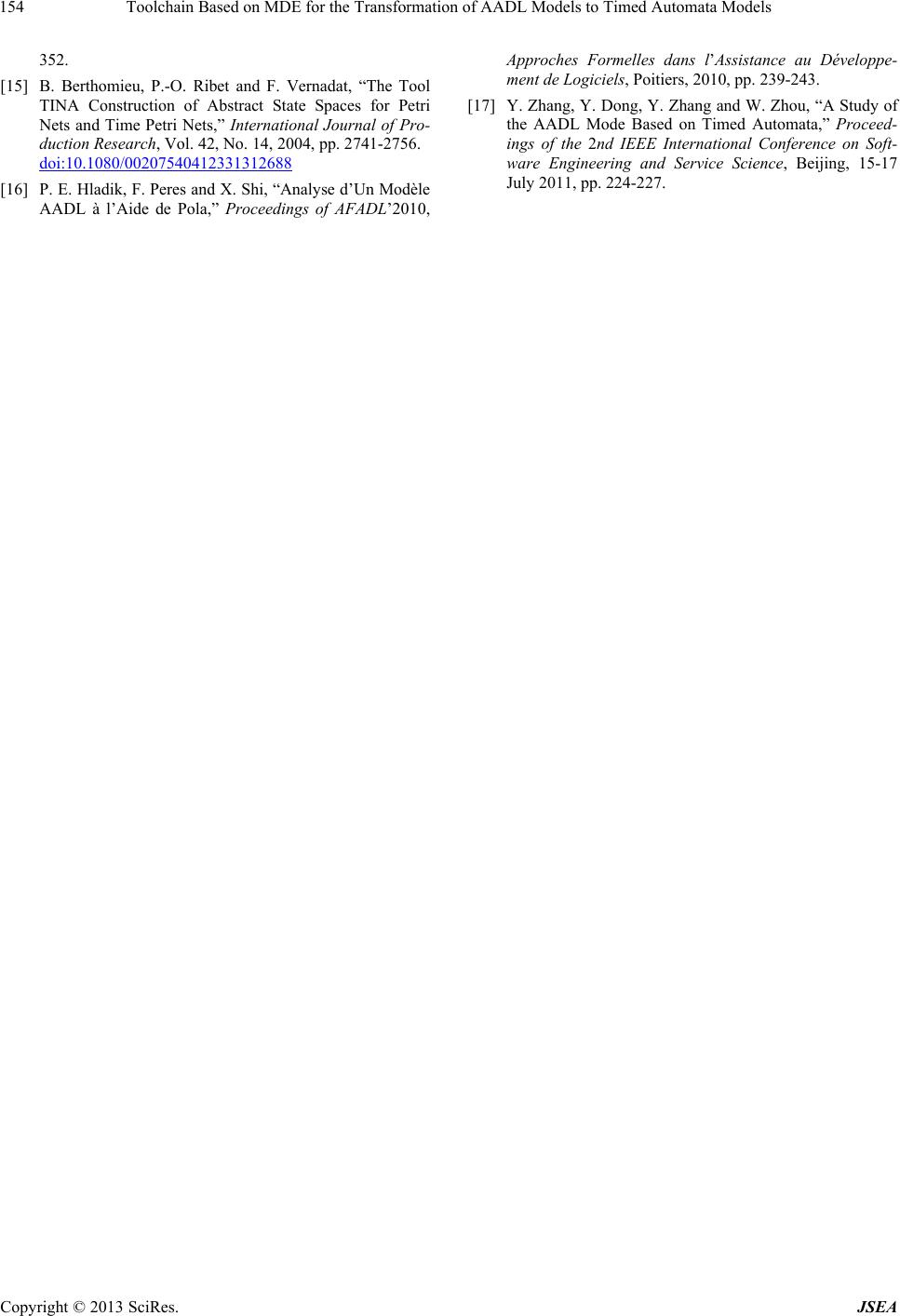
AADL architecture. The general idea is to extract a timed
automaton for capturing the behavior of AADL architec-
ture, and then verify using the Uppaal toolbox that it re-
spects the constraints of the specification. The proposed
approach strictly follows the principles of MDE. So, we
have defined a meta-model for AADL (source model)
and another meta-model for timed automaton (target
model). Then, we defined a transformation process in
two steps that takes as input an AADL model and pro-
duces as output a code accepted by Uppaal. We validated
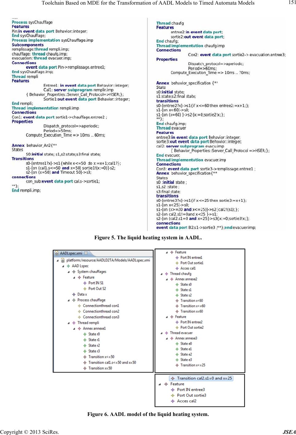
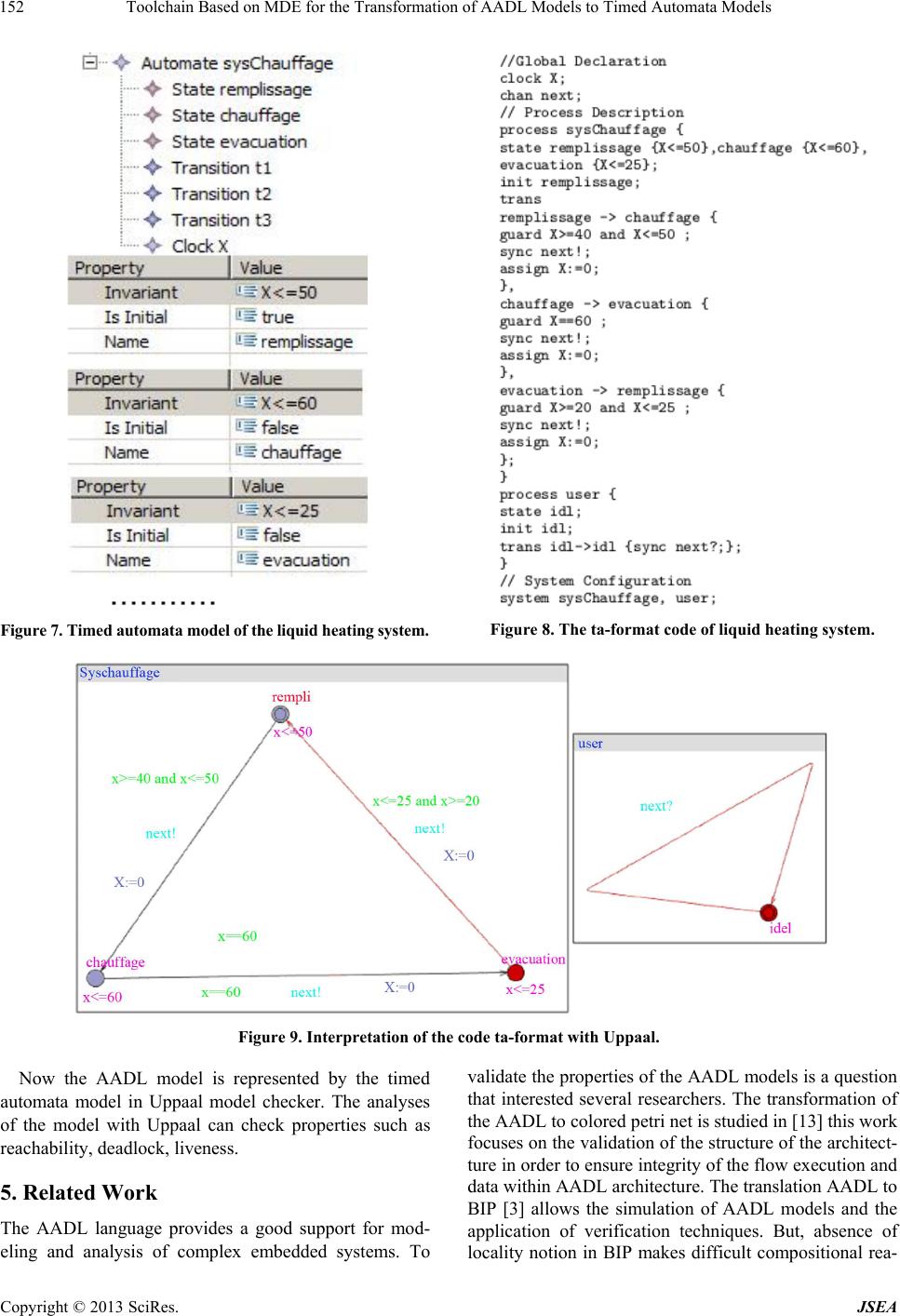
the presented approach through the example of liquid
heating system.
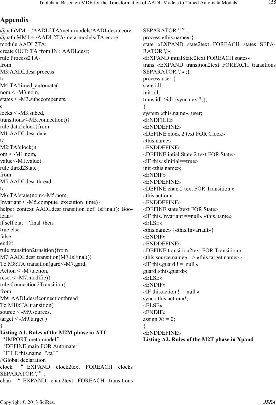
This work will continue by the use of Uppaal toolbox
to simulate the behavior of the timed automaton and ver-
ify the properties of it. We will also study the feedback
of the results. In addition, it is interesting to validate the
proposed approach through other more complicated ex-
amples in order to evaluate the efficiency of the ap-
proach.
7. Acknowledgements
We would like to thank Boucherit Imen and Benghazi
Ratiba for their insight regarding structure simulation.
We also would like to thank the anonymous reviewers
for their constructive comments. This work is supported
in part by CNEPRU project registered in University
Abbes Laghrour of Khenchela (Algeria) under grant
b*035201- 20005.
REFERENCES
[1] R. Lämmel, J. Saraiva and J. Visser, “Generative and
Transformational Techniques in Software Engineering,”
Lecture Notes in Computer Science, Vol. 4143, 2006, pp
36-64. doi:10.1007/11877028
[2] SAE International, “Architecture Analysis & Designe
Language (AADL),” Standard Version 2, 2009.
[3] M. Chkouri, A. Robert, M. Bozga and J. Sifaksi, “Trans-
lating AADL into BIP-Application to the Verification or
Real-Time Systems,” Proceedings of MODELSACES-
MB-Model Based Architecting and Construction of Em-
bedded Systems, 2008, pp. 5-19.
[4] R. Alur and D. L. Dill, “A Theory of Timed Automata,”
Theoretical Computer Science, Vol. 126, No. 2, 1994, pp.
183-236. doi:10.1016/0304-3975(94)90010-8
[5] J. Bengtsson and W. Yi, “Timed Automata: Semantics,
Algorithms and Tools,” Lecture Notes in Computer Sci-
ence, Vol. 3098, 2004, pp. 87-124.
[6] K. G. Larsen, P. Pettersson and W. Yi, “Uppaal in a Nut-
shell,” International Journal on Software Tools for Tech-
nology Transfer, Vol. 1, 1997, pp. 134-152.
doi:10.1007/s100090050010
[7] D. A. Olivero, S. Tripakis and S. Yovine, “The Tool
KRONOS Hybrid Systems III: Verification and Control,”
Lecture Notes in Computer Science, Vol. 1066, 1996, pp.
208-219.
[8] D. Steinberg, F. Budinsky, M. Paternostro and E. Merks,
“Eclipse Modeling Framework-Chapter Ecore Modeling
Concepts,” 2nd Edition, Addison-Wesley, Boston, 2008.
[9] M. E. Hamdane and A. Chaoui, “Specification and Veri-
fication of Timed Automaton Using Meta-Modeling and
Graph Grammars,” Proceedings of the 4th IEEE Interna-
tional Conference on the Applications of Digital Informa-
tion and Web Technologies, Stevens Point, 2011, pp. 137-
142.
[10] F. Jouault and I. Kurtev, “On the Architectural Alignment
of ATL and QVT,” ACM Symposium on Applied Com-
puting (SAC’06), 2006.
[11] F. Jouault and I. Kurtev, “On the Architectural Alignment
of ATL and QVT,” Proceedings of the SAC06 ACM
Symposium on Applied Computing, 2006, pp.1188-1195.
[12] Xpand Documentation, 2010.
http://ditec.um.es/ssdd/xpand_reference.pdf
[13] T. Vergnaud, “Modélisation des Systèmes Temps-Réel
Répartis Embarqués pour la Génération Automatique
d’Applications Formellement Vérifiées,” Ph.D. Thesis,
École Nationale Supérieure des Télécommunications,
2006.
[14] L. Pi, J. P. Bodeveix, M. Filali and M. K. Dianfum, “A
Comparative Study of FIACRE and TASM to Define
AADL Real Time Concepts,” Proceedings of the 14th
IEEE International Conference on Engineering of Com-
plex Computer Systems, Potsdam, 2-4 June 2009, pp. 347-
Copyright © 2013 SciRes. JSEA
Toolchain Based on MDE for the Transformation of AADL Models to Timed Automata Models
Copyright © 2013 SciRes. JSEA
154
352.
[15] B. Berthomieu, P.-O. Ribet and F. Vernadat, “The Tool
TINA Construction of Abstract State Spaces for Petri
Nets and Time Petri Nets,” International Journal of Pro-
duction Research, Vol. 42, No. 14, 2004, pp. 2741-2756.
doi:10.1080/00207540412331312688
[16] P. E. Hladik, F. Pere s and X. Shi, “Analyse d’Un Modèle
AADL à l’Aide de Pola,” Proceedings of AFADL’2010,
Approches Formelles dans lAssistance au Développe-
ment de Logiciels, Poitiers, 2010, pp. 239-243.
[17] Y. Zhang, Y. Dong, Y. Zhang and W. Zhou, “A Study of
the AADL Mode Based on Timed Automata,” Proceed-
ings of the 2nd IEEE International Conference on Soft-
ware Engineering and Service Science, Beijing, 15-17
July 2011, pp. 224-227.
Toolchain Based on MDE for the Transformation of AADL Models to Timed Automata Models 155
Appendix
@pathMM = /AADL2TA/meta-models/AADLdesr.ecore
@path MM1 = /AADL2TA/meta-models/TA.ecore
module AADL2TA;
create OUT: TA from IN : AADLdesr;
rule Process2TA{
from
M3:AADLdesr!process
to
M4:TA!timed_automata(
nom < -M3.nom,
states < -M3.subccompenets,
c
locks < -M3. subcd,
transitions<-M3.connectiont)}
rule data2clock{from
M1:AADLdesr!data
to
M2:TA!clock(n
om < -M1.nom,
value<-M1.value)
rule thred2State{
from
M5:AADLdesr!thread
to
M6:TA!state(nom<-M5.nom,
Invariant < -M5.compute_ex ecution_ time)}
helper context AADLdesr!transition def: IsFinal(): Boo-
lean=
if self.etat = 'final' then
true else
false
endif;
rule transition2trnsition{from
M7:AADLdesr!transition(M7.IsFinal())
To M8:TA!transition(gard<-M7.gard,
Action < -M7.action,
reset < -M7.modifie)}
rule Connection2Transition{
from
M9: AADLdesr!connectionthread
To M10:TA!transition(
source < -M9.sources,
target < -M9.target )
}
Listing A1. Rules of the M2M phase in ATL
IMPORT meta-model
DEFINE main FOR Automate
FILE this.name+".ta"
//Global declaration
clock EXPAND clock2text FOREACH clocks
SEPARATOR ',';
chan EXPAND chan2text FOREACH transitions
SEPARATOR ',';
process «this.name» {
state «EXPAND state2text FOREACH states SEPA-
RATOR ','»;
«EXPAND intialState2text FOREACH states»
trans «EXPAND transition2text FOREACH transitions
SEPARATOR ','» ;}
process user {
state idl;
init idl;
trans idl->idl {sync next?;};
}
system «this.name», user;
«ENDFILE»
«ENDDEFINE»
«DEFINE clo ck 2 text FOR Clock»
«this.name»
«ENDDEFINE»
«DEFINE intial State 2 text FOR State»
«IF this.isInitial==true»
init «this.name»;
«ENDIF»
«ENDDEFINE»
«DEFINE chan 2 text FOR Transition »
«this.action»
«ENDDEFINE»
«DEFINE state2text FOR State»
«IF this.Invariant ==null» «th is.name»
«ELSE»
«this.name» {«this.Invariant»}
«ENDIF»
«ENDDEFINE»
«DEFINE transition2text FOR Transition»
«this.source.name» - > «this.target.name» {
«IF this.guard ! = 'null'»
guard «this.guard»;
«ELSE»
«ENDIF»
«IF this.action ! = 'null'»
sync «this.action»!;
«ELSE»
«ENDIF»
assign X: = 0;
}
«ENDDEFINE»
Listing A2. Rules of the M2T phase in Xpand
Copyright © 2013 SciRes. JSEA