Engineering, 2013, 5, 245-250
http://dx.doi.org/10.4236/eng.2013.53035 Published Online March 2013 (http://www.scirp.org/journal/eng)
Gear Drive Mechanism for Continuous Variable Valve
Timing of IC Engines
Osama H. M. Ghazal1, Mohamad S. H. Dado2
1Mechanical Engineering Department, Applied Science Private University, Amman, Jordan
2Mechanical Engineering Department, The University of Jordan, Amman, Jordan
Email: hamzy211@yahoo.com, dado@ju.edu.jo
Received December 18, 2012; revised January 15, 2013; accepted January 23, 2013
ABSTRACT
Continuous variable valve actuating (CVVA) technology provides high potential in achieving high performance, low
fuel consumption and pollutant reduction. To get full benefits from (CVVT) various types of mechanisms have been
proposed and designed. Some of these mechanisms are in production and have shown significant benefits in improving
engine performance. In this investigation a newly designed gear drive mechanism that controls the intake valve opening
(IVO) and closing (IVC) angles is studied. The control scheme is based on maximizing the engine brake power (P) and
specific fuel consumption (BSFC) at any engine speed by continuously varying the phase between the cam shaft angle
and the crank shaft angle. A single-cylinder engine is simulated by the “LOTUS” software to find out the optimum
phase angle for maximum power and minimum fuel consumption at a given engine speed. The mechanism is a plane-
tary gear drive designed for precise and continuous control. This mechanism has a simple design and operation condi-
tions which can change the phase angle without limitation.
Keywords: Mechanism Design; Planetary Gear; Variable Valve Timing; Spark Ignition Engines; Performance
1. Introduction
In internal combustion engines, variable valve timing
(VVT), also known as variable valve actuation (VVA), is
a generalized term used to describe any mechanism or
method that can alter the shape or timing of a valve lift
event within an internal combustion engine [1-6]. The
(VVT) system allows the lift, duration or timing (in vari-
ous combinations) of the intake and/or exhaust valves to
be changed while the engine is in operation, which have a
significant impact on engine performance and emissions.
In a standard engine, the valve events are fixed, so per-
formance at different loads and speeds is always a com-
promise between drivability (power and torque), fuel
economy and emissions. An engine equipped with a
variable valve actuation system is freed from this con-
straint, allowing performance to be improved over the
engine operating range [7-10].
Some types of variable valve control systems optimize
power and torque by varying valve opening times and/or
duration. Some of these valve control systems optimize
performance at low and mid-range engine speeds. Others
focus on enhancing only high-rpm power. Other systems
provide both of these benefits by controlling valve timing
and lift. There are many ways in which this can be
achieved, ranging from mechanical devices to hydraulic,
pneumatic and camless systems [11-14]. Hydraulic sys-
tem suffer from many problems including viscosity
change of the hydraulic medium due to the temperature
change, the liquid tends to act like a solid at high speed,
and hydraulic systems must be carefully controlled, which
require the use of powerful computers and very precise
sensors. Pneumatic system utilizing pneumatics to drive
the engine valves would in all probability not be feasible
because of their complexity and the very large amount of
energy required for compressing the air. Camless system
(or, free valve engine) uses electromagnetic, hydraulic, or
pneumatic actuators to open the poppet valves instead.
Common problems include high power consumption,
accuracy at high speed, temperature sensitivity, weight
and packaging issues, high noise, high cost, and unsafe
operation in case of electrical problems. Multiair system
(or Uniair) is an electro-hydraulic variable valve actuation
technology controlling air intake (without a throttle valve)
in petrol or diesel engines. The system allows optimum
intake valve opening schedules, which gives full control
over valve lift and timing.
2. Continuous Variable Valve Timing
(CVVT)
First, the (CVVT) system offers a unique ability to have
C
opyright © 2013 SciRes. ENG
O. H. M. GHAZAL, M. S. H. DADO
246
independent control of the intake and exhaust valves in an
internal combustion engine [15-17]. For any engine load
criteria, the timing of intake and exhaust can be inde-
pendently programmed and the engine’s performance
could be optimized under all conditions. However, if
valve timing could be controlled independent of crank-
shaft rotation, then a near infinite number of valve timing
scenarios could be accommodated which would dra-
matically improve fuel economy and emission levels of an
automobile. These systems are used in several automo-
biles with gasoline engine like Toyota, Nissan, Honda,
and others. In 2010, Mitsubishi developed and started
mass production of its 4N13 1.8 L DOHC I4 world’s first
passenger car diesel engine that features a variable valve
timing system.
One of the high effective mechanisms proposed for
controlling variable valve timing is planetary gear me-
chanism. The planetary gearbox arrangement is an eng-
ineering design that offers many advantages. One ad-
vantage is its unique combination of both compactness
and outstanding power transmission efficiencies. A ty-
pical efficiency loss in a planetary gearbox arrangement is
only 3% per stage. This type of efficiency ensures that a
high proportion of the energy being input is transmitted
through the gearbox, rather than being wasted on me-
chanical losses inside the gearbox. Another advantage of
the planetary gearbox arrangement is load distribution.
Because the load being transmitted is shared between
multiple planets, torque capability is greatly increased.
The more planets in the system the greater load ability and
the higher the torque density. The planetary gearbox
arrangement also creates greater stability due to the even
distribution of mass and increased rotational stiffness.
Hence, in this work we will present a new design of
planetary gear drive mechanism for Continuous variable
valve timing IC engine.
3. The Gear Drive Mechanism Design
After the text edit has been completed, the paper is ready
for the template. Duplicate the template file by using the
save as command, and use the naming convention pre-
scribed by your journal for the name of your paper. In
this newly created file, highlight all of the contents and
import your prepared text file. You are now ready to
style your paper.
3.1. A Description
The proposed gear drive mechanism is designed by Prof.
M. Dado from mechanical engineering department at the
University of Jordan. This mechanism guarantees a pre-
cise and continuous camshaft phasing for intake and ex-
haust valves in internal combustion engine. The phase
angle between the camshaft and crankshaft changes re-
lated to engine’s speed, which improve engine’s per-
formance and emissions.
The mechanism shown in Figure 1 is a planetary gear
train system consisting from an external sun gear (3),
planetary gears (2) carried by two planet arms (1), and an
internal ring gear (4) with external worm teeth meshing
with a worm gear (5) which is connected to a stepper
motor interfaced to the engine computer control system.
When the stepper motor shaft is stationary, which is the
prevailing case, the ring gear is also stationary. This yields
a constant speed ratio between the crank shaft and the
camshaft. A rotation of the stepper motor shaft leads to the
rotation of the ring gear resulting in additional rotation for
the planetary gears and the external sun gear and the
camshaft. This additional rotation results in phase change
between the crank shaft and the cam shaft.
3.2. Mechanism Installation
The mechanism is operated by planetary gear train to
continuously and precisely change the phase angle be-
tween camshaft and crank shaft. The internal ring gear has
an external worm tooth so it can acts like a worm wheel. It
trains with the worm. The mechanism is operated by
planetary gear train to continuously and precisely change
the phase angle between camshaft and gear. The four
identically planetary gears are meshing with the ring gear
and the sun gear and they are carried by the two arms.
The mechanism (Figure 2) is installed to the internal
combustion engine as follows: the mechanism is carried
by bearing in such way that the camshaft (6) and the sun
gear shaft are coaxial and then shafts are connected by the
Figure 1. The components of the mechanism.
Copyright © 2013 SciRes. ENG
O. H. M. GHAZAL, M. S. H. DADO 247
Figure 2. The mechanism installation.
spline coupling (7). One of the planet arms (1) is con-
nected with the crank shaft (9) by chain or timing belt (8).
The worm gear shaft is connected mechanically with a
stepper motor. The stepper motor is equipped with sensors
and power supply, which are connected to the CPU to
control the motion of the worm gear.
3.3. The Method of Operation
The method of the mechanism operation is easy and sim-
ple and it’s described below:
1) When the stepper motor shaft is stationary, which is
the prevailing case, the ring gear is also stationary. The
rotation of the arm by the crank shaft causes the rotation of
the ring according to the equation:
4
3
1
1
T
T1




(1)
where:
ω3—the speed of the sun gear (3), which is also the
speed of the camshaft;
ω1—the speed of the arm (1).
T1 and T4 are the number of teeth of the sun gear and the
number of internal teeth for the ring gear, respectively.
The relationship between the number of teeth for the
sun gear, planetary gears, and internal ring gear is:
43
2TT T2
(2)
where:
T2—the number of teeth for the planetary gears (2).
2) When the stepper motor have a signal from the CPU
it will rotate according to the required shift angle resulting
in the rotation of the worm gear (5), which will cause the
rotation of the ring gear and consequently an additional
rotation of the planetary gears.
3) This rotation resulting in additional rotation for the
sun gear, which is connected with the camshaft, according
to the following equation
35
3
46
TT
TT 5
 (3)
where:
Δθ3—the shift angle for the camshaft;
Δθ5—the angle of rotation for the worm gear;
T5, T6—the number of teeth for worm gear and external
teeth for the ring gear, respectively.
4) The arm will not be affected by this rotation, because
it is coupled to the crankshaft.
5) The additional rotation for the sun gear which is
connected to the camshaft results in phase change between
camshaft and crank shaft of value Δθ1.
3.4. The Advantages of the Mechanism
The main advantages of the above mechanism over other
mechanisms can be summarized as follows:
1) The change in the phase angle is constrained to the
motion of the stepper motor, which can be controlled with
accuracy up to 1.8 degrees for each step with zero over-
shoot. This value will be smaller for the camshaft de-
pending on the gear teeth numbers.
2) The worm gear, which is connected to the stepper
motor and meshing with ring gear, offers a self-locking
mechanism for ring gear. That will guarantee a constant
speed ratio between the camshaft and crank shaft for
specific phase angle, which is necessary for good engine
operation.
3) In this mechanism there is no limitation for phase
angle changing value, except the limitation imposed by
the engine’s performance envelop.
4. Cam Phasing Optimization—Maximizing
Power Output
In this work, the optimum values for intake and exhaust
valve timing have been calculated to maximize brake
power. These values were used to calculate and compro-
mise the brake power and fuel consumption for different
engine’s speeds and compression ratios. For the purpose
of analyzing the engine characteristics the dimensions
were considered with Lotus Engineering Software. The
Lotus Engine Simulation and analysis program is an
in-house code developed by LOTUS ENGINEERING
Company since the late 1980’s. Validation of global per-
Copyright © 2013 SciRes. ENG
O. H. M. GHAZAL, M. S. H. DADO
Copyright © 2013 SciRes. ENG
248
which means that one revolution of the arm results in 4
revolutions of the camshaft (and the sun gear). This re-
quires keeping the velocity ratio between crankshaft and
the arm equals two to obtain the velocity ratio between the
camshaft and the crankshaft equals two, which is neces-
sary for four stroke IC engine operation.
formance parameters of power, volumetric efficiency and
fuel consumption has been performed on a wide range of
current production engines.
The simulation model of 4-cylinder engine (Figure 3)
has been built to find out the optimum phase angle for
maximum power. The engine geometry data and valve
timings are as shown in Table 1. Input data such as inlet
pressure, temperature, equivalence ratio are also intro-
duced for all runs. Also the required exit data such as the
back pressure are given. The calculations were carried out
for the default and optimum values of valve timing which
are given in Table 2. The optimization engine variable is
to find the maximum brake power output. The speed is
varied from 1000 - 6000 rpm. The effects of optimum
valve timings values and default values on the brake
power and for different compression ratio (CR) are illus-
trated in Table 3 and Figure 4 through 6.
On the other hand, the relationship between the stepper
motor angle and camshaft angle is obtain from Equation
(3)
35 5
353
46 7.5
NN
NN

 (6)
That mean when the stepper motor (and worm gear)
rotates 7.5 degrees, the camshaft rotates one additional
degree.
The dimensions of the mechanism can be found as fol-
lowing: we assume that planetary gear, sun gear, and ring
gear are helical gears with helical angle ψ = 30˚ and
module m = 1 [mm] and the face width f = 20 [mm]. In
addition, the worm teeth has lead angle χ = 10˚ and axial
pitch p = 2 [mm]. From these assumptions we find out that
the diameter of the mechanism are not more than 150 ×
150 × 50 [mm], so it can be installed in engine room eas-
ily.
5. The Application of the Mechanism
(Example)
The data given in Table 2 were used to calculate the re-
quired values of shift angle for worm gear. To illustrate
the work of the above mentioned mechanism we have
made the following assumptions: 6. Conclusion
3256
20, 20, 2, 45TTTT (4)
A planetary gear drive mechanism is designed and im-
plemented to optimize the performance of a four stroke
single-cylinder engine. The mechanism precisely and
continuously changes the phase angle between the cam
shaft and crank shaft angles. The effect of optimizing the
phase angle at a given speed on the brake power is
From Equations (1) and (2) we get:

4
31
202 2060
and
4
T


(5)
Figure 3. The simulation model of IC engine.
O. H. M. GHAZAL, M. S. H. DADO 249
Table 1. Base engine geometry, fuel is gasoline (C8H18).
Type of engine 4-stroke
Bore 82 mm
Stroke 80 mm
No. of cylinders 4
Compression ratio 8 - 14
Inlet throat dia. 26.5 mm
Exhaust throat dia. 22.5 mm
Max. valve lift 8 mm
IVO angle bTDC 10 deg
IVC angle aBDC 66 deg
EVO angle bBDC 38 deg
EVC angle bTDC 38 deg
Speed 1000 - 6000 rpm
Table 2. Optimum values of valve timing for maximum
power and different speeds.
Valve timings Inlet valve timing Exhaust valve timing
Speed,
rpm
Open,
bTDC
Close,
aBDC
Open,
bBDC
Close,
aTDC
1000 25˚ 30˚ 55˚ 32˚
2000 33˚ 37˚ 65˚ 39˚
3000 44˚ 43˚ 70˚ 45˚
4000 49˚ 47˚ 70˚ 51˚
5000 51˚ 50˚ 70˚ 53˚
6000 57˚ 60˚ 70˚ 57˚
Table 3. (a) Brake power for optimum and default values of
valve timing for different speeds; (b) Brake power for op-
timum and default values of valve timing for different
speeds.
(a)
CR 8 CR 10
Speed rpm Opti Def % incre Opti Def % incre
1000 3.73 2.78 34 4.1 2.98 37
2000 7.8 6.09 28 8.35 6.52 28
3000 11.7 9.37 25 12.56 10.05 25
4000 15.31 12.4 23 16.47 13.38 23
5000 18.56 15.2 22 20.07 16.43 22
6000 21.39 17.7 21 23.22 19.13 21
(b)
CR 12 CR 14
Speed, rpm Opti Def % incre Opti Def % incre
1000 4.21 3.11 35 4.3 3.24 33
2000 8.76 6.8 29 9.07 7.06 28
3000 13.1 10.5 25 13.69 10.91 25
4000 17.3 14.0 23 18.01 14.58 24
5000 21.1 17.3 22 22.02 17.97 23
6000 24.5 20.2 22 25.62 21.03 22
Figure 4. The effect of optimum valve values and default
values on brake power (CR 8).
(a)
(b)
Figure 5. (a) The effect of optimum valve values and default
values on brake power (CR 10); (b) The effect of optimum
valve values and default values on brake power (CR 12).
Figure 6. The effect of optimum valve values and default
values on brake power (CR 14).
Copyright © 2013 SciRes. ENG
O. H. M. GHAZAL, M. S. H. DADO
250
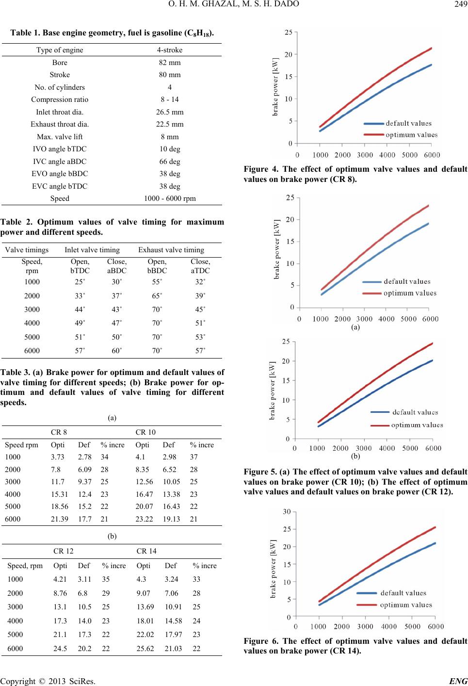
appreciable. The increase of the brake power ranges be-
tween 21% and 35% depending on the engine speed and
compression ratio as indicated in Table 3. This increase is
large at low engine speed and drops as the engine speed
increases. It could be concluded that the implementation
of the proposed mechanism in four stroke engines im-
proves the engine performance and efficiency.
REFERENCES
[1] S. Bohac and D. Assanis, “Effects of Exhaust Valve Tim-
ing on Gasoline Engine Performance and Hydrocarbon
Emissions,” SAE Technical Paper No. 2004-01-058, 2004.
[2] T. H. Ma, “Effect of Variable Engine Valve Timing on
Fuel Economy,” SAE Technical Paper No. 880390, 1988.
[3] C. Gray, “A Review of Variable Engine Valve Timing,”
SAE Technical Paper No. 880386, 1988.
[4] T. Ahmad and M. A. Theobald, “A Survey of Variable
Valve-Actuation Technology,” SAE Technical Paper No.
891674, 1989.
[5] T. Dresner and P. Barkan, “A Review and Classification
of Variable Valve Timing Mechanisms,” SAE Paper, No.
890667, 1989.
[6] S. Diana, B. Lorio, V. Giglio and G. Police, “The Effect
of Valve Lift Shape and Timing on Air Motion and Mix-
ture Formation of DISI Engines Adopting Different VVA
Actuators,” SAE Paper No. 2001-01-3553, 2001.
[7] P. Kreuter, P. Heuser and M. Schebitz, “Strategies to
Improve SI-Engine Performance by Means of Variable
Intake Lift, Timing and Duration,” SAE Paper No. 920449,
1992.
[8] G. Fontana and E. Galloni, “Variable Valve Timing for
Fuel Economy Improvement in a Small Spark-Ignition
Engine,” Applied Energy, Vol. 39, No. 86, 2009, pp. 96-
105. doi:10.1016/j.apenergy.2008.04.009
[9] Y. Ping, X. Zhang, Y. Dong, G. Zhu and Q. Wang, “Study
on Performance Improvement of Vehicle Engine by Us-
ing Variable Cam Timing,” Chinese Internal Combustion
Engine Engineering, Vol. 29, No. 6, 2008, pp. 20-23.
[10] H. S. Yan, M. C. Tsai and M. H. Hsu, “An Experimental
Study of the Effects of Cam Speed on Cam-Follower
Systems,” Mechanism and Machine Theory, Vol. 31, No.
4, 1996, pp. 397-412.
doi:10.1016/0094-114X(95)00087-F
[11] F. Bozza, A. Gimelli, A. Senatore and A. Caraceni, “A
Theoretical Comparison of Various VVA Systemsfor Per-
formance and Emission Improvement of SI Engines,”
SAE Technical Paper No. 2001-01-0670, 2001.
[12] N. Kosuke, K. Hiroyuki and K. Kazuya, “Valve Timing
and Valve Lift Control Mechanism for Engines,” Mecha-
tronics, Vol. 16, No. 5, 2006, pp. 121-129.
[13] W. H. Hsieh, “An Experimental Study on Cam Controlled
Planetary Gear Trains,” Mechanism and Machine Theory,
Vol. 42, No. 5, 2007, pp. 513-525.
doi:10.1016/j.mechmachtheory.2006.10.006
[14] W.-H. Hsieh, “Kinematic Synthesis of Cam-Controlled
Planetary Gear Trains,” Mechanism and Machine Theory,
Vol. 44, No. 3, 2009, pp. 873-895.
doi:10.1016/j.mechmachtheory.2008.07.001
[15] H. S. Yan and W. R. Chen, “On the Output Motion Cha-
racteristics of Variable Speed Input Servo-Controlled Slider-
Crank Mechanisms,” Mechanism and Machine Theory, Vol.
35, No. 4, 2000, pp. 541-561.
doi:10.1016/S0094-114X(99)00023-3
[16] H. Hong, G. B. Parvate-Patil and B. Gordon, “Review
and Analysis of Variable Valve Timing Strategies-Eight
Ways to Approach,” Proceedings of the Institution of Me-
chanical Engineers, Part D: Journal of Automobile En-
gineering, Vol. 218, No. 10, 2004, pp. 1179-1200.
doi:10.1177/095440700421801013
[17] F. Bozza, A. Gimelli and R. Tuccillo, “The Control of a
VVA-Equipped SI Engine Operation by Meansof 1D
Simulation and Mathematical Optimization,” SAE Tech-
nical Paper No. 2002-01-1107, 2002.
Copyright © 2013 SciRes. ENG