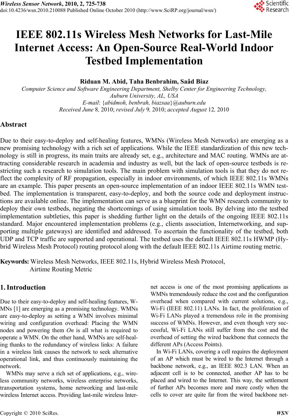
 Wireless Sensor Network, 2010, 2, 725-738 doi:10.4236/wsn.2010.210088 October 2010 (http://www.SciRP.org/journal/wsn/) Copyright © 2010 SciRes. WSN Published Online IEEE 802.11s Wireless Mesh Networks for Last-Mile Internet Access: An Open-Source Real-World Indoor Testbed Implementation Riduan M. Abid, Taha Benbrahim, Saâd Biaz Computer Science and Software Engineering Department, Shelby Center for Engineering Technology, Auburn University, AL, USA E-mail: {abidmoh, benbrah, biazsaa}@auburn.edu Received June 8, 2010; revised July 9, 2010; accepted August 12, 2010 Abstract Due to their easy-to-deploy and self-healing features, WMNs (Wireless Mesh Networks) are emerging as a new promising technology with a rich set of applications. While the IEEE standardization of this new tech- nology is still in progress, its main traits are already set, e.g., architecture and MAC routing. WMNs are at- tracting considerable research in academia and industry as well, but the lack of open-source testbeds is re- stricting such a research to simulation tools. The main problem with simulation tools is that they do not re- flect the complexity of RF propagation, especially in indoor environments, of which IEEE 802.11s WMNs are an example. This paper presents an open-source implementation of an indoor IEEE 802.11s WMN test- bed. The implementation is transparent, easy-to-deploy, and both the source code and deployment instruc- tions are available online. The implementation can serve as a blueprint for the WMN research community to deploy their own testbeds, negating the shortcomings of using simulation tools. By delving into the testbed implementation subtleties, this paper is shedding further light on the details of the ongoing IEEE 802.11s standard. Major encountered implementation problems (e.g., clients association, Internetworking, and sup- porting multiple gateways) are identified and addressed. To ascertain the functionality of the testbed, both UDP and TCP traffic are supported and operational. The testbed uses the default IEEE 802.11s HWMP (Hy- brid Wireless Mesh Protocol) routing protocol along with the default IEEE 802.11s Airtime routing metric. Keywords: Wireless Mesh Networks, IEEE 802.11s, Hybrid Wireless Mesh Protocol, Airtime Routing Metric 1. Introduction Due to their easy-to-deploy and self-healing features, W- MNs [1] are emerging as a promising technology. WMNs are easy-to-deploy as setting a WMN involves minimal wiring and configuration overhead: Placing the WMN nodes and powering them On is all what is required to operate a WMN. On the other hand, WMNs are self-heal- ing thanks to the redundancy of wireless links: A failure in a wireless link causes the network to seek alternative operational link, and thus continuously maintaining the network. WMNs may serve a rich set of applications, e.g., wire- less community networks, wireless enterprise networks, transportation systems, home networking and last-mile wireless Internet access. Providing last-mile wireless Inter- net access is one of the most promising applications as WMNs tremendously reduce the cost and the configuration overhead when compared with current solutions, e.g., Wi-Fi (IEEE 802.11) LANs. In fact, the proliferation of Wi-Fi LANs played a tremendous role in the promising success of WMNs. However, and even though very suc- cessful, Wi-Fi LANs still suffer from the cost and the overhead of setting the wired backbone that connects the different APs (Access Points). In Wi-Fi LANs, covering a cell requires the deployment of an AP which must be wired to the Internet through a backbone network, e.g., an IEEE 802.3 LAN. When an adjacent cell is to be connected, another AP has to be placed and wired to the Internet. This way, the settlement of further APs becomes more and more costly when the cells to cover are quite far from the wired backbone net-  R. M. ABID ET AL. Copyright © 2010 SciRes. WSN 726 work. Furthermore, in case of dense regions, a parallel dense deployment of APs is needed to meet customers’ needs, thus resulting in more wiring and settlement over- head. Even though APs are relatively inexpensive, wiring the APs and finding the appropriate canals for the wires remains expensive. In IEEE 802.11s WMNs, no wiring is required except for the AP which will serve as a gateway towards the Internet, even though the gateway AP can be wirelessly connected to the Internet. All other APs serve as routers and route data on behalf of each other towards/from the gateway AP. Therefore, covering a cell reduces to adding an AP without wiring it to the backbone network. This way, the WMN technology is considerably easing wireless cov- erage, especially when compared to the actual Wi-Fi WLANs solution. A fact which is of tremendous impor- tance to industry since easing wireless coverage equates affording more coverage, and thus supports more user connections, which finally induces a greater return to in- dustry. In this context, IETF (Internet Engineering Task Force) is actively working to finalize the IEEE 802.11s standard which will pave the way towards a successful worldwide industrialization of this promising technology. In 2005, IETF set a mesh networking TG (Task Group) to standardize IEEE 802.11s. The work is still in progress, and the last IEEE 802.11s TG meeting was held in March, 2010 [2]. Even though the standard is not final yet, its main traits are set, e.g., architecture and MAC routing. The IEEE 802.11s TG set HWMP (Hybrid Wireless Mesh Protocol) [3] as a default routing protocol for IEEE 802.11s compli- ant devices. HWMP uses MAC addresses for routing. Fur- ther, Airtime [4] has been set as a default routing metric for HWMP. These two amendments aim to maintain a mini- mum compatibility between the IEEE 802.11s devices to be manufactured by different companies. Albeit a new technology, several WMNs solutions are already commercialized (e.g., by Strix Systems, Cisco, Nortel, Tropos, BelAir). Besides, valuable real-world de- ployments are in place too, e.g., the MIT Roofnet [5] and the Microsoft Mesh Networking project [6]. However, these deployments are not compliant to the new IEEE 802.11s standard and are proprietary. The absence of non-proprietary and open-source testbeds is restricting the proliferation of the research in WMNs by forcing researchers to use simulation tools, e.g., ns-2 [7] and Qualnet [8]. Even though simulators are relatively good at approximating most of the real-world networking applications, they are still quite far from doing so in wire- less indoor environments, which is the case with IEEE 802.11s WMN technology. In wireless indoor environ- ments, an accurate RF propagation simulation is very cru- cial and it largely affects the overall network performance. For instance, RF propagation is of paramount importance in determining interferences levels. These latter has proved to be of great impact to the overall performance of mul- ti-hop wireless networks [9,10]. However, an accurate RF propagation simulation of indoor environments remains quite impossible. Indeed, simulators cannot capture the complex aspects of RF propagation such as multi-path fading, interferences, path loss, reflection and diffraction. In indoor environments, the situation is further aggravated because of the unpre- dictable and mobile nature of obstacles, e.g., furniture, people, walls, etc. This unpredictable and mobile nature of obstacles has a direct and strong impact on the behavior of most RF propagation characteristics, basically reflection, diffraction, and path loss. These facts render very complex an accurate modeling of the interferences phenomenon. Thus, most simulation tools remain simplistic in the way they are modeling interferences. For instance, ns-2, which is the most widely used tool in academia, uses a simplified version of the physical interference model (the capture threshold model) that accounts for only one interfere at a time [11]. This is definitely not the case in real-world in- terferences where they can be caused by different simulta- neous interferes. Nevertheless, simulators are still very common in research since they remain the sole experimen- tation alternative when the deployment costs of a real- world testbed are not affordable. In this context, we are presenting an open-source real- world IEEE 802.11s WMN testbed implementation that would encourage the academia WMN research community to migrate to the use of real world testbeds, instead of simulators, by deploying the proposed testbed or by using it as a blueprint for deploying their own testbed. The pre- sented testbed is easy-to-deploy as it uses off-the-shelf commodity hardware and software. The linux-based test- bed code is open-source, written in C language, and avail- able online [12]. Besides serving the purpose of allowing the WMN researches to easily build their own WMN test- bed, the testbed can serve as a building block for a widely- used open-source WMN. By delving into the testbed implementation subtleties, this paper sheds further light into the new IEEE 802.11s standard and addresses major encountered implementation problems such as clients association, Internetworking and supporting multiple gateways. Clients’ association problem stems from the fact that the original IEEE 802.11 MAC addresses are lost once the corresponding frames leave the WMN towards the Internet. To address this problem, we propose a time-efficient mechanism that maps back to the original IEEE 802.11 MAC addresses and their associating access points, and handles mobile stations hand-offs. With Internetworking, we propose a NAT (Network Address Translation) mechanism that solves the problem of the ir- relevance of the IP addresses of the Wi-Fi legacy stations  R. M. ABID ET AL.727 outside WMNs. This irrelevance stems mainly from IEEE 802.11s mesh nodes using MAC addresses for routing. By using MAC addresses for routing, the WMN nodes are not contributing to the non-mesh IP routing protocols, e.g., RIP and OSPF. And last, when multiple gateways are present, there is always a better route to every operational gateway, and deciding on the best gateway to select requires a way for inspecting the status of every gateway. We propose a mechanism that uses timestamps for synchronizing be- tween the different gateways. To ascertain the functionality of the testbed, both TCP and UDP were tested using real-world traffic. Real-world web browsing sessions from Wi-Fi enabled stations, using the testbed as a wireless backhaul, are operational. The current testbed uses 15 nodes and spans two separate loca- tions that are connected through the Internet. The testbed implements the IEEE 802.11s HWMP routing protocol along with the IEEE 802.11s default Airtime routing metric. However, it is very important to mention that this work is not meant to evaluate the performance of the new IEEE 802.11s standard but to present an easy-to-deploy, open-source real-world in-door IEEE 802.11s WMN test- bed implementation that can serve as a seed for further WMN testbed implementations. The primary contributions of this work are: Presenting an easy-to-deploy and open-source IEEE 802.11s WMN testbed implementation. Encouraging academic researchers, on IEEE 802.11s WMNs, to use real-world testbeds. Highlighting and solving major implementation is- sues, e.g., clients’ association problem, Internetworking WMNs, and supporting multiple gateways. Highlighting the main traits of the new IEEE 802.11s standard. Highlighting and implementing the new IEEE 802.11s HWMP routing protocol and the IEEE 802.11s Airtime routing metric. The rest of the paper is organized as follows: Section 2 overviews the main specifications of the IEEE 802.11 standard. Section 3 highlights the details of the HWMP routing protocol and the Airtime routing metric. The im- plementation details and the encountered problems are respectively covered in Sections 4 and 5. Section 6 out- lines the necessary steps to deploy the testbed. In Section 7, we present the experimental settings of the testbed, the topologies and the experimental results. Finally, Section 8 presents the conclusion and alludes for future work. 2. IEEE 802.11s Overview The IEEE 802.11s standard started initially as a study group in 2003, and then became a Task Group in July, 2004. The first draft was accepted in March, 2006 and the last TG meeting was held in March, 2010 [2]. The stan- dard is concerned with five main areas: 1) Architecture 2) Routing in MAC layer 3) MAC enhancements 4) Internetworking 5) Security This work pertains to areas 1, 2 and 4. Areas 1 and 2 are introduced in next paragraphs, while area 4 is de- ferred to Section 5. 2.1. IEEE 802.11s Architecture IEEE 802.11s defines three types of stations: 1) MPs (Mesh Points): MPs are wireless stations that perform routing only. 2) MAPs (Mesh Access Points): MAPs are MPs with additional access point capabilities. Besides performing routing, MAPs aggregate traffic from/towards legacy 802.11 stations. A MAP can be thought of as a legacy access point which performs routing also. 3) MPPs (Mesh Portal Points): MPPs are MPs that serve as gateways to other non-mesh networks, e.g., In- ternet. MPPs aggregate traffic from/towards the non- mesh networks. To illustrate the functionality of every mesh node type, Figure 1 depicts a scenario where an end user, e.g., a Wi-Fi enabled station, is browsing the Internet. The end- user, at station sta1, is connected to a legacy IEEE 802.11 network through a mesh access point (MAP). The MAP is routing frames, and has mesh point (MP2) as a next-hop. Mesh point (MP2) has mesh point (MP4) as its next-hop and MP7 afterwards. This latter forwards data towards the Mesh Portal Point (MPP1) which serves as a gateway to- wards the Internet web server. The role of the routing pro- tocol is to determine the best sequence of hops for a data frame to get to its final destination. In IEEE 802.11s, rout- ing is performed using MAC addresses and uses Airtime [4] as a routing metric. 2.2. Routing at MAC Layer Multi-hop routing is a key element in IEEE 802.11s. IEEE Figure 1. IEEE 802.11s WMN architecture. Copyright © 2010 SciRes. WSN  R. M. ABID ET AL. Copyright © 2010 SciRes. WSN 728 802.11s performs routing using MAC addresses and uses either four or six MAC addresses depending on the nature of the traffic. When both the source and the destination are mesh points in the WMN, only four addresses are used. When the source or the destination is outside the WMN, i.e., a non-mesh point (e.g., an IEEE 802.11 or an IEEE 802.3 station), six addresses are used. The IEEE 802.11s frame header bear an AE (Address Extension) mode bit that discriminates between the two modes. In the cases where WMNs are used for last-mile Internet access, the AE bit is set to 1 as both the destination and the source are non-mesh points. The scenario, formerly illustrated in Fig- ure 1, is a relevant case as the source is a wireless station residing in an IEEE 802.11 network, and the destination is a web server residing in the Internet. Adding two extra MAC addresses, to the ordinary four IEEE 802.11 addresses, is meant to track the MAC ad- dresses of the non-mesh source and non-mesh destination as these would be lost once the frame enters/quits the mesh network. The IEEE 802.11s six MAC addresses are: 1) Destination MAC Address: MAC address of the next- hop in a given route. 2) Source MAC Address: MAC address of the sender. 3) Destination Proxy Address: MAC address of the des- tination MPP/MAP from where the frame will leave the mesh network. 4) Source Proxy Address: MAC address of the MPP/ MAP from where the frame entered into the mesh network. 5) Final Destination Address: MAC address of the final non-mesh destination. 6) Originator Address: MAC address of the non-mesh station that originated the frame. 3. MAC Routing in IEEE 802.11s HWMP [3] is a hybrid protocol being both reactive and proactive. The two behaviors can be used separately or simultaneously depending on the application. 3.1. Reactive Routing in HWMP RM-AODV (Radio-Metric Ad hoc On Demand Distance Vector) [13] is the reactive protocol in HWMP. RM- AODV is an adaptation of the AODV [14] protocol that uses Airtime [4] as a link quality metric. Reactive rout- ing protocols initiate route discovery requests only when needed, such as in case of a route failure or a route time- expiration. In RM-AODV, when a node needs a path to a certain destination, it broadcasts a PREQ (Path Request) mes- sage that contains the MAC address of the destination. Every PREQ message bears a unique sequence number that distinguishes it from other PREQ messages. When an intermediate MP receives a PREQ message, it first checks the freshness of the received message by compar- ing its sequence number with the last locally stored se- quence number. A PREQ message is processed only when it has a greater sequence number or when it has the same sequence number but exhibiting a better route. After receiving a fresher PREQ message, intermediate nodes update their reverse path towards the source, update the routing metric by including the weight of the last hop, and then re-broadcast the updated PREQ message. Subse- quent MPs proceed the same way until the PREQ reaches the destination. When the destination MP receives the PREQ message, it checks its freshness in the same way as other intermediate MPs, and then it updates its reverse path towards the source. The destination then formulates a RREP (Route Reply) message which is afterwards uni-casted towards the source. Intermediate MPs receiving the RREP message update their forward path towards the destination, update the rout- ing metric, and then forward the updated RREP towards the source. In case of node failure, the intermediate MPs detecting the failure send a RERR (Route Error) message towards the source to inform it about the breakage of the link. The source can then re-initiate a new route discovery using a new PREQ message. 3.2. Proactive Routing in HWMP The HWMP proactive mode [3] is a tree based routing [15, 16]. In the proactive mode, every root mesh point (i.e., MPP) periodically broadcasts PREQ messages bearing unique sequence numbers. The protocol is very similar to reactive HWMP, presented in Subsection 3.1, in how in- termediate nodes react and process PREQ messages. The only differences are: In reactive HWMP, PREQ messages are sent in a re- active way (i. e., when needed), whereas in proactive HWMP, PREQ messages are sent proactively (i.e ., in ad- vance) and on a periodic basis (e.g., every 1 second). In reactive HWMP, PREQ can be sent by any mesh node type (MP, MAP and MPP), whereas in proactive HWMP, PREQ messages are sent only by MPPs. These latter represent the trees roots. MPs and MAPs do only forward PREQ messages. By having every MPP periodically broadcasting PREQ messages, tree-like topologies are built with MPPs as roots and MAPs as leaves. By comparing the routing metrics of the different PREQ messages, MAPs select the best MPP and thus adhere to the tree whose root is the selected MPP. The proactive protocol is ideal for the scenario where WMNs are used for last-mile Internet access since most of the traffic is directed towards/from the gateway MPPs that connect the WMN to the Internet. 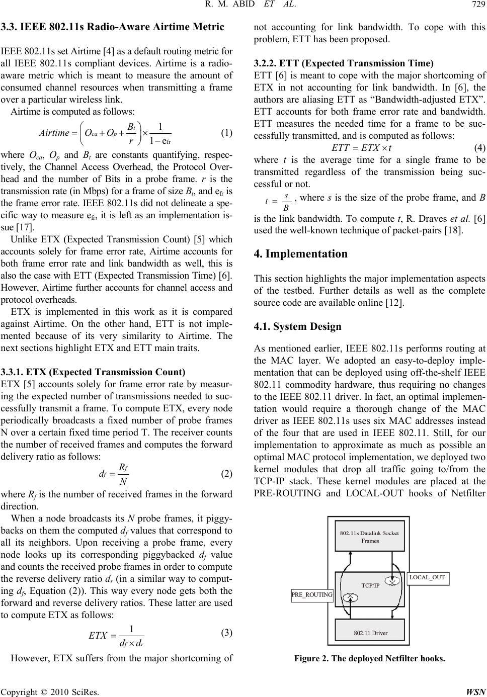 R. M. ABID ET AL.729 3.3. IEEE 802.11s Radio-Aware Airtime Metric IEEE 802.11s set Airtime [4] as a default routing metric for all IEEE 802.11s compliant devices. Airtime is a radio- aware metric which is meant to measure the amount of consumed channel resources when transmitting a frame over a particular wireless link. Airtime is computed as follows: fr 1 1e t ca p B Airtime O Or (1) where Oca, Op and Bt are constants quantifying, respec- tively, the Channel Access Overhead, the Protocol Over- head and the number of Bits in a probe frame. r is the transmission rate (in Mbps) for a frame of size Bt, and efr is the frame error rate. IEEE 802.11s did not delineate a spe- cific way to measure efr, it is left as an implementation is- sue [17]. Unlike ETX (Expected Transmission Count) [5] which accounts solely for frame error rate, Airtime accounts for both frame error rate and link bandwidth as well, this is also the case with ETT (Expected Transmission Time) [6]. However, Airtime further accounts for channel access and protocol overheads. ETX is implemented in this work as it is compared against Airtime. On the other hand, ETT is not imple- mented because of its very similarity to Airtime. The next sections highlight ETX and ETT main traits. 3.3.1. ETX (Expected Transmission Count) ETX [5] accounts solely for frame error rate by measur- ing the expected number of transmissions needed to suc- cessfully transmit a frame. To compute ETX, every node periodically broadcasts a fixed number of probe frames N over a certain fixed time period T. The receiver counts the number of received frames and computes the forward delivery ratio as follows: f R dN (2) where Rf is the number of received frames in the forward direction. When a node broadcasts its N probe frames, it piggy- backs on them the computed df values that correspond to all its neighbors. Upon receiving a probe frame, every node looks up its corresponding piggybacked df value and counts the received probe frames in order to compute the reverse delivery ratio dr (in a similar way to comput- ing df, Equation (2)). This way every node gets both the forward and reverse delivery ratios. These latter are used to compute ETX as follows: 1 r ETX dd (3) However, ETX suffers from the major shortcoming of not accounting for link bandwidth. To cope with this problem, ETT has been proposed. 3.2.2. ETT (Expected Transmission Time) ETT [6] is meant to cope with the major shortcoming of ETX in not accounting for link bandwidth. In [6], the authors are aliasing ETT as “Bandwidth-adjusted ETX”. ETT accounts for both frame error rate and bandwidth. ETT measures the needed time for a frame to be suc- cessfully transmitted, and is computed as follows: ETTETX t (4) where t is the average time for a single frame to be transmitted regardless of the transmission being suc- cessful or not. s t, where s is the size of the probe frame, and B is the link bandwidth. To compute t, R. Draves et al. [6] used the well-known technique of packet-pairs [18]. 4. Implementation This section highlights the major implementation aspects of the testbed. Further details as well as the complete source code are available online [12]. 4.1. System Design As mentioned earlier, IEEE 802.11s performs routing at the MAC layer. We adopted an easy-to-deploy imple- mentation that can be deployed using off-the-shelf IEEE 802.11 commodity hardware, thus requiring no changes to the IEEE 802.11 driver. In fact, an optimal implemen- tation would require a thorough change of the MAC driver as IEEE 802.11s uses six MAC addresses instead of the four that are used in IEEE 802.11. Still, for our implementation to approximate as much as possible an optimal MAC protocol implementation, we deployed two kernel modules that drop all traffic going to/from the TCP-IP stack. These kernel modules are placed at the PRE-ROUTING and LOCAL-OUT hooks of Netfilter Figure 2. The deployed Netfilter hooks. Copyright © 2010 SciRes. WSN 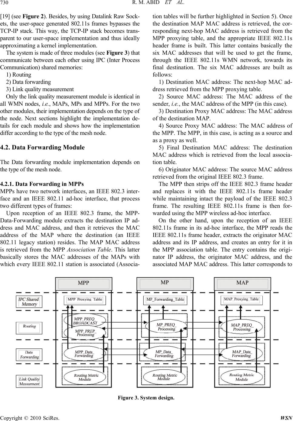 R. M. ABID ET AL. Copyright © 2010 SciRes. WSN 730 [19] (see Figure 2). Besides, by using Datalink Raw Sock- ets, the user-space generated 802.11s frames bypasses the TCP-IP stack. This way, the TCP-IP stack becomes trans- parent to our user-space implementation and thus ideally approximating a kernel implementation. The system is made of three modules (see Figure 3) that communicate between each other using IPC (Inter Process Communication) shared memories: 1) Routing 2) Data forwarding 3) Link quality measurement Only the link quality measurement module is identical in all WMN nodes, i.e., MAPs, MPs and MPPs. For the two other modules, their implementation depends on the type of the node. Next sections highlight the implementation de- tails for each module and shows how the implementation differ according to the type of the mesh node. 4.2. Data Forwarding Module The Data forwarding module implementation depends on the type of the mesh node. 4.2.1. Data Forwarding in MPPs MPPs have two network interfaces, an IEEE 802.3 inter- face and an IEEE 802.11 ad-hoc interface, that process two different types of frames: Upon reception of an IEEE 802.3 frame, the MPP- Data-Forwarding module extracts the destination IP ad- dress and MAC address, and then it retrieves the MAC address of the MAP where the destination (an IEEE 802.11 legacy station) resides. The MAP MAC address is retrieved from the MPP Association Table. This latter basically stores the MAC addresses of the MAPs with which every IEEE 802.11 station is associated (Associa- tion tables will be further highlighted in Section 5). Once the destination MAP MAC address is retrieved, the cor- responding next-hop MAC address is retrieved from the MPP proxying table, and the appropriate IEEE 802.11s header frame is built. This latter contains basically the six MAC addresses that will be used to get the frame, through the IEEE 802.11s WMN network, towards its final destination. The six MAC addresses are built as follows: 1) Destination MAC address: The next-hop MAC ad- dress retrieved from the MPP proxying table. 2) Source MAC address: The MAC address of the sender, i.e., the MAC address of the MPP (in this case). 3) Destination Proxy MAC address: The MAC address of the destination MAP. 4) Source Proxy MAC address: The MAC address of the MPP. The MPP, in this case, is acting as a source and as a proxy as well. 5) Final Destination MAC address: The destination MAC address which is retrieved from the local associa- tion table. 6) Originator MAC address: The source MAC address retrieved from the original IEEE 802.3 frame. The MPP then strips off the IEEE 802.3 frame header and replaces it with the IEEE 802.11s frame header while maintaining intact the payload of the IEEE 802.3 frame. The resulting IEEE 802.11s frame is then for- warded using the MPP wireless ad-hoc interface. On the other hand, upon the reception of an IEEE 802.11s frame in its ad-hoc interface, the MPP reads the IEEE 802.11s frame header, extracts the originator MAC address and its IP address, and creates an entry for it in the MPP association table. The entry contains the origi- nator IP address, the originator MAC address, and the associated MAP MAC address. This latter corresponds to Figure 3. System design.  R. M. ABID ET AL. 731 the source Proxy MAC address (Address 4 in the IEEE 802.11s frame header, see Subsection 2.2). Afterwards, the MPP strips off the IEEE 802.11s frame header and replaces it with an IEEE 802.3 frame header containing the local MPP MAC address as a source address. 4.2.2. Data Forwarding in MPs In contrast to MPPs, Data Forwarding in MPs is quite straightforward as it deals with only one type of frames: IEEE 802.11s frames. However, the MP still has to deal with two types of frames that differ in terms of their final destination which can be either in an IEEE 802.3 network (e.g., frame destined to Internet) or in a IEEE 802.11 net- work (frame destined to a Wi-Fi station). In other words, the two frames can differ in terms of whether their final destination, within the WMN, is either a MPP or a MAP. The proxy type, either a MPP or an MPP, is made transparent in our implementation by having the same type of entry in the MP forwarding table for all proxies. The MP forwarding table entries contain basically the destination proxy MAC address, the MAC address of the next-hop in the route towards destination, the route se- quence number, and the route metric. Upon reception of an IEEE 802.11s frame, the MP ex- tracts the destination proxy address, i.e., the MPP or MAP MAC address, consults its forwarding table and retrieves the corresponding entry which contains the next-hop MAC address. The IEEE 802.11s frame is then updated by changing only two of the six MAC addresses in the IEEE 802.11s frame header. The remaining four are kept intact. The two updated MAC addresses are the destination MAC address and the source MAC address which become, respectively, the retrieved next-hop MAC address and the MP MAC address. 4.2.3. Data Forwarding in MAPs MAPs have two network interfaces, a managed mode (i.e., Access point) IEEE 802.11 interface and an ad-hoc mode IEEE 802.11 interface, that process two different types of frames: Upon reception on an IEEE 802.11 frame, from its access point interface, the MAP first reads the source MAC address and then formulates the six MAC ad- dresses in the IEEE 802.11s header frame as follows: 1) Destination MAC address: The MAC address of the next-hop in the path towards the destination MPP. This is retrieved from the MAP proxying table. 2) Source MAC address: The MAC address of the lo- cal MAP. 3) Destination Proxy Address: The MAC address of the MPP for which the frame is destined. It is retrieved from the MAP proxying table, and corresponds to the best MPP in case of supporting multiple gateways. 4) Source Proxy Address: The MAC address of local MAP. 5) Final Destination: Unknown at this stage. A NULL address is put in. 6) Originator: The source MAC address, retrieved from the original IEEE 802.11 frame. The MAP then strips off the IEEE 802.11 header, re- places it with the shaped IEEE 802.11s header, and for- wards the frame through its ad-hoc IEEE 802.11 interface. On the other side, upon reception of a IEEE 802.11s frame in its ad-hoc interface, the IEEE 802.11s header frame is stripped off, while keeping the frame payload in- tact, and replaced by a broadcast IEEE 802.11 header frame. 4.3. Routing Module The routing module implementation depends on the type of the mesh node. 4.3.1. Routing in MPPs In MPPs, the routing module is made of two sub-modules: 1) MPP-PREQ-Broadcast module: periodically broad- casts PREQ messages which consist basically of the MAC address of the local MPP, a unique sequence number, and the routing metric field. 2) The MPP-RREP-Processing module: processes RREP (Route Reply) messages forwarded by intermediate MPs and originating from different MAPs. Upon reception of a RREP message, the MPP extracts the MAC address of the source MAP, looks up its entry it the MPP proxying table, and updates the corresponding routing metric (by adding the metric of the last hop) as well as the corresponding next-hop in the reverse path towards the MAP who initi- ated the RREP message. Thus, besides acknowledging PREQ messages, RRE messages set reverse paths towards the source MAPs as well. 4.3.2. Routing in MPs In MPs, the MP-PREQ-Processing module processes two types of messages: PREQ and RREP messages. PREQ message are originating from MPPs and RREP messages are originating from MAPs. Upon reception of a PREQ message, the module checks first the freshness of the message in order to process it as only fresher messages must be considered. First, the module extracts the MAC address of the sender MPP, then uses this address to look up its corresponding entry in the MP forwarding table. (The MP forwarding table entries store, among other values, the last fresh se- quence numbers that correspond to the different MPPs). Once the last sequence number is retrieved, the PREQ C opyright © 2010 SciRes. WSN  R. M. ABID ET AL. Copyright © 2010 SciRes. WSN 732 message is discarded in case it corresponds to a non- fresh message (i.e., of a smaller sequence number). If the PREQ message is a new one then the routing module updates its reverse path entry towards the corresponding MPP. Afterwards, the PREQ message is updated by ad- justing the routing metric value. The module retrieves the routing metric value, e.g. ETX or Airtime, that corre- sponds to the link from where the MP received the PREQ message and adds it to the current PREQ routing metric, then rebroadcasts the message. If the PREQ message is of equal freshness as the current sequence number, the PREQ message is then processed only and only if it corresponds to a better route. If that is the case, the PREQ is processed as if it was a fresh PREQ message. Upon reception of a RREP message, the MP extracts the MAC address of the sender MAP, looks up its entry in the forwarding table, and then updates the corre- sponding reverse path to the MAP. To forward the re- ceived RREP message, the MP looks up the destination MPP MAC address and retrieves its entry from the for- warding table. The retrieved entry contains the MAC address of the next-hop in the route towards the destina- tion MPP. Afterwards, the routing metric in the RREP message is updated, and then the message is forwarded towards the next-hop. 4.3.3. Routing in MAPs Upon reception of a PREQ message, the MAP-PREQ- Processing module retrieves the MAC address of the MPP which issued the PREQ message, then retrieves the entry (from the proxying table) that corresponds to the sender MPP and checks the freshness of the current PREQ message. If the PREQ message is a fresh one, then the corresponding entry in the MAP proxying table is updated and the routing metric value is updated the same way as with MPs. Still, since the PREQ sequence numbers pertain to only one single MAP, the selected route (having the best routing metric and a fresh sequence number) would cor- respond to the best route leading to one specific MPP, and since there can be other MPPs (i.e., multiple gate- ways), other better routes to other MPPs may exist as well. To address this problem, we keep a routing entry, in the MAP proxying table, for every MPP, and we time- stamp those entries with the time they were last updated in order to assure the selection of the MPP that has the best route as well as a fresh route (Further details, on the multiple gateways problem, are presented in Section 5). Once the proxying table is updated, a RREP message, that acknowledges the receipt of the MPP PREQ mes- sage, is formed and sent back to the selected MPP. The RREP message consists mainly of the MAC address of the MAP as well as the corresponding routing metric. 4.4. Airtime Measurement Module As presented in Subsection 3.3, Airtime is computed as follows: fr 1 1e t ca p B Airtime O Or (5) According to the Equation (5), Airtime depends on two basic variables: The frame error rate efr and the bit rate r. The other constants depend solely on the underlying mod- ulation technique, see Table 1. To compute the frame error rate, we first compute the reverse and the forward delivery ratios (The details of these ratios were presented in Subsection 3.3.1). Once the reverse and forward delivery ratios are computed, they are used to infer the reverse and forward failure ratios as follows: 1, 1rrf df df These latter are used to approximate the frame error rate as follows: rrefff The way the forward and reverse delivery ratios are computed is covered in next section. The bit rates are extracted using the “/Proc” system files, and the rate adaptation algorithm was kept to the default, which is SampleRate [20] in Madwifi drivers [21]. 4.4.1. ETX Module The ETX module consists of two sub-modules: The ETX- Broadcast module and the ETX-Collect module. 1) The ETX-Broadcast module periodically broadcasts probe frames (e.g., 1 frame per second) embedding the number of probe frames received in the reverse path from every neighboring MP during a certain time period T. ETX-Broadcast does not compute the reverse delivery ratios, it gets them from the ETX-Collect module via IPC (Inter Process Communication) shared memories. 2) ETX-Collect is the module that computes the ETX values for all links towards neighboring MPs. First, in or- der to compute the reverse delivery ratios, the module counts the number of broadcast probe frames received from every single neighboring MP during the period of time T. Once computed, these ratios are communicated to the ETX-Broadcast module in order to piggyback them in the broadcast probe frames. On the other side of neighboring MPs, when a MP receives a probe frame, its ETX-Collect module extracts the corresponding reverse delivery ratio that were embedded by the ETX-Broadcast module of the sender MP and counts, at the same time, the received probe frame as well in order to infer the corresponding forward Table 1. IEEE 802.11s airtime metric constants. IEEE 802.11 a IEEE 802.11 b/g Oca 75 µs 335 µs Op 110 µs 364 µs 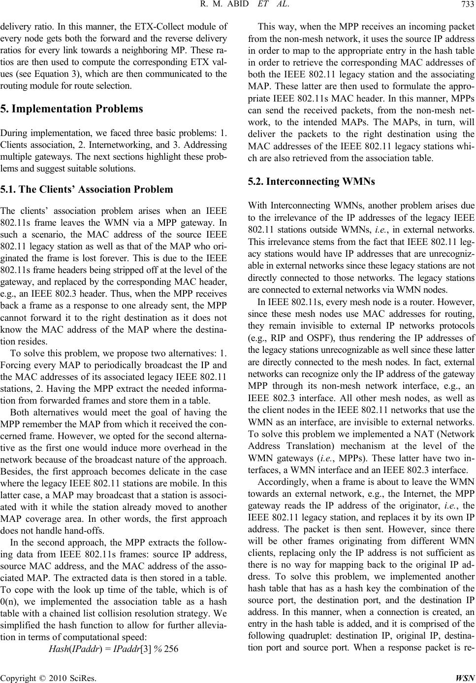 R. M. ABID ET AL.733 delivery ratio. In this manner, the ETX-Collect module of every node gets both the forward and the reverse delivery ratios for every link towards a neighboring MP. These ra- tios are then used to compute the corresponding ETX val- ues (see Equation 3), which are then communicated to the routing module for route selection. 5. Implementation Problems During implementation, we faced three basic problems: 1. Clients association, 2. Internetworking, and 3. Addressing multiple gateways. The next sections highlight these prob- lems and suggest suitable solutions. 5.1. The Clients’ Association Problem The clients’ association problem arises when an IEEE 802.11s frame leaves the WMN via a MPP gateway. In such a scenario, the MAC address of the source IEEE 802.11 legacy station as well as that of the MAP who ori- ginated the frame is lost forever. This is due to the IEEE 802.11s frame headers being stripped off at the level of the gateway, and replaced by the corresponding MAC header, e.g., an IEEE 802.3 header. Thus, when the MPP receives back a frame as a response to one already sent, the MPP cannot forward it to the right destination as it does not know the MAC address of the MAP where the destina- tion resides. To solve this problem, we propose two alternatives: 1. Forcing every MAP to periodically broadcast the IP and the MAC addresses of its associated legacy IEEE 802.11 stations, 2. Having the MPP extract the needed informa- tion from forwarded frames and store them in a table. Both alternatives would meet the goal of having the MPP remember the MAP from which it received the con- cerned frame. However, we opted for the second alterna- tive as the first one would induce more overhead in the network because of the broadcast nature of the approach. Besides, the first approach becomes delicate in the case where the legacy IEEE 802.11 stations are mobile. In this latter case, a MAP may broadcast that a station is associ- ated with it while the station already moved to another MAP coverage area. In other words, the first approach does not handle hand-offs. In the second approach, the MPP extracts the follow- ing data from IEEE 802.11s frames: source IP address, source MAC address, and the MAC address of the asso- ciated MAP. The extracted data is then stored in a table. To cope with the look up time of the table, which is of 0(n), we implemented the association table as a hash table with a chained list collision resolution strategy. We simplified the hash function to allow for further allevia- tion in terms of computational speed: Hash(IPaddr) = IPaddr[3] % 256 This way, when the MPP receives an incoming packet from the non-mesh network, it uses the source IP address in order to map to the appropriate entry in the hash table in order to retrieve the corresponding MAC addresses of both the IEEE 802.11 legacy station and the associating MAP. These latter are then used to formulate the appro- priate IEEE 802.11s MAC header. In this manner, MPPs can send the received packets, from the non-mesh net- work, to the intended MAPs. The MAPs, in turn, will deliver the packets to the right destination using the MAC addresses of the IEEE 802.11 legacy stations whi- ch are also retrieved from the association table. 5.2. Interconnecting WMNs With Interconnecting WMNs, another problem arises due to the irrelevance of the IP addresses of the legacy IEEE 802.11 stations outside WMNs, i.e., in external networks. This irrelevance stems from the fact that IEEE 802.11 leg- acy stations would have IP addresses that are unrecogniz- able in external networks since these legacy stations are not directly connected to those networks. The legacy stations are connected to external networks via WMN nodes. In IEEE 802.11s, every mesh node is a router. However, since these mesh nodes use MAC addresses for routing, they remain invisible to external IP networks protocols (e.g., RIP and OSPF), thus rendering the IP addresses of the legacy stations unrecognizable as well since these latter are directly connected to the mesh nodes. In fact, external networks can recognize only the IP address of the gateway MPP through its non-mesh network interface, e.g., an IEEE 802.3 interface. All other mesh nodes, as well as the client nodes in the IEEE 802.11 networks that use the WMN as an interface, are invisible to external networks. To solve this problem we implemented a NAT (Network Address Translation) mechanism at the level of the WMN gateways (i.e., MPPs). These latter have two in- terfaces, a WMN interface and an IEEE 802.3 interface. Accordingly, when a frame is about to leave the WMN towards an external network, e.g., the Internet, the MPP gateway reads the IP address of the originator, i.e., the IEEE 802.11 legacy station, and replaces it by its own IP address. The packet is then sent. However, since there will be other frames originating from different WMN clients, replacing only the IP address is not sufficient as there is no way for mapping back to the original IP ad- dress. To solve this problem, we implemented another hash table that has as a hash key the combination of the source port, the destination port, and the destination IP address. In this manner, when a connection is created, an entry in the hash table is added, and it is comprised of the following quadruplet: destination IP, original IP, destina- tion port and source port. When a response packet is re- Copyright © 2010 SciRes. WSN 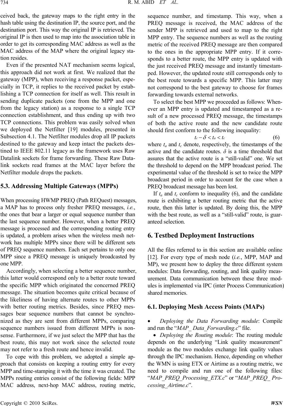 R. M. ABID ET AL. Copyright © 2010 SciRes. WSN 734 ct ceived back, the gateway maps to the right entry in the hash table using the destination IP, the source port, and the destination port. This way the original IP is retrieved. The original IP is then used to map into the association table in order to get its corresponding MAC address as well as the MAC address of the MAP where the original legacy sta- tion resides. Even if the presented NAT mechanism seems logical, this approach did not work at first. We realized that the gateway (MPP), when receiving a response packet, espe- cially in TCP, it replies to the received packet by estab- lishing a TCP connection for itself as well. This result in sending duplicate packets (one from the MPP and one from the legacy station) as a response to a single TCP connection establishment, and thus ending up with two TCP connections. This problem was easily solved when we deployed the Netfilter [19] modules, presented in Subsection 4.1. The Netfilter modules drop all IP packets destined to the gateway and keep intact the packets des- tined to IEEE 802.11 legacy as the framework uses Raw Datalink sockets for frame forwarding. These Raw Data- link sockets read frames at the MAC layer before the Netfilter module drops the packets. 5.3. Addressing Multiple Gateways (MPPs) When processing HWMP PREQ (Path REQuest) messages, a MAP has to process only fresher PREQ messages, i.e., the ones that bear a larger or equal sequence number than the last sequence number. However, when a better PREQ message is processed and the corresponding routing entry is updated, a problem arises when the wireless mesh net- work has multiple MPPs since there will be different sets of PREQ sequence numbers. Each set pertains to only one MPP since a PREQ message is uniquely broadcasted by one MPP. Accordingly, when selecting a better sequence number, this latter would correspond only to a better route toward the specific MPP which originated the concerned PREQ message. The situation becomes quite critical because of the likeliness of having alternate routes to other MPPs with better routing metrics. Besides, since PREQ mes- sages bear sequence numbers that cannot be synchro- nized as they are sent from different MPPs, comparing sequence numbers issued from different MPPs is non- sense. Furthermore, if we just select the MPP that has the best route, this may not work since the selected route may not refer to a fresh route and hence invalid. To cope with this problem, we adopted a simple ap- proach that consists on keeping a routing entry for every MPP and time-stamping it with the time it was created. The MPPs routing entries consist of the following fields: MPP MAC address, next-hop MAC address, routing metric, sequence number, and timestamp. This way, when a PREQ message is received, the MAC address of the sender MPP is retrieved and used to map to the right MPP entry. The sequence numbers as well as the routing metric of the received PREQ message are then compared to the ones in the appropriate MPP entry. If it corre- sponds to a better route, the MPP entry is updated with the just received PREQ message and instantly timestam- ped. However, the updated route still corresponds only to the best route towards a specific MPP. This latter may not correspond to the best gateway to choose for frames forwarding towards external networks. To select the best MPP we proceeded as follows: When- ever an MPP entry is updated and timestamped as a re- sult of a new processed PREQ message, the timestamps of both the active route and the new candidate route should first conform to the following inequality: catt (6) where ta and tc denote, respectively, the timestamps of the active and the candidate routes. δ is a time threshold that assures that the active route is a “still-valid” one. We set the threshold to depend on the MPP broadcast period. The experimental value of the threshold is set to twice the MPP broadcast period in order to account for the case when a PREQ broadcast message has been lost. If ta and tc conform to inequality (6), and the candidate route is exhibiting a better routing metric that the active route, then this latter is updated. By doing this, the MPP with the best route, as well as a “still-valid” route, is guar- anteed selection. 6. Testbed Deployment Instructions All the files referred to in this section are available online [12]. For every type of mesh node (i.e., MPP, MAP and MP), we present how to deploy the three different system modules: Data forwarding, routing, and link quality meas- urement. Data communication between these three mod- ules is implemented via IPC (inter Process Communication) shared memories. 6.1. Deploying Mesh Access Points (MAPs) Deploying the Data Forwarding module: Compile and run the “MAP_ Data_Forwarding.c” file. Deploying the Routing module: The routing module depends on the underlying “Link quality measurement” module as the two modules exchange link quality values through the IPC mechanism. Hence, depending on whether the WMN is using ETX or Airtime as a routing metric, we need to compile and run one of the following files: “MAP_PREQ_Processing_ETX.c” or “MAP_PREQ_ Pro- cessing_Airtime.c”. 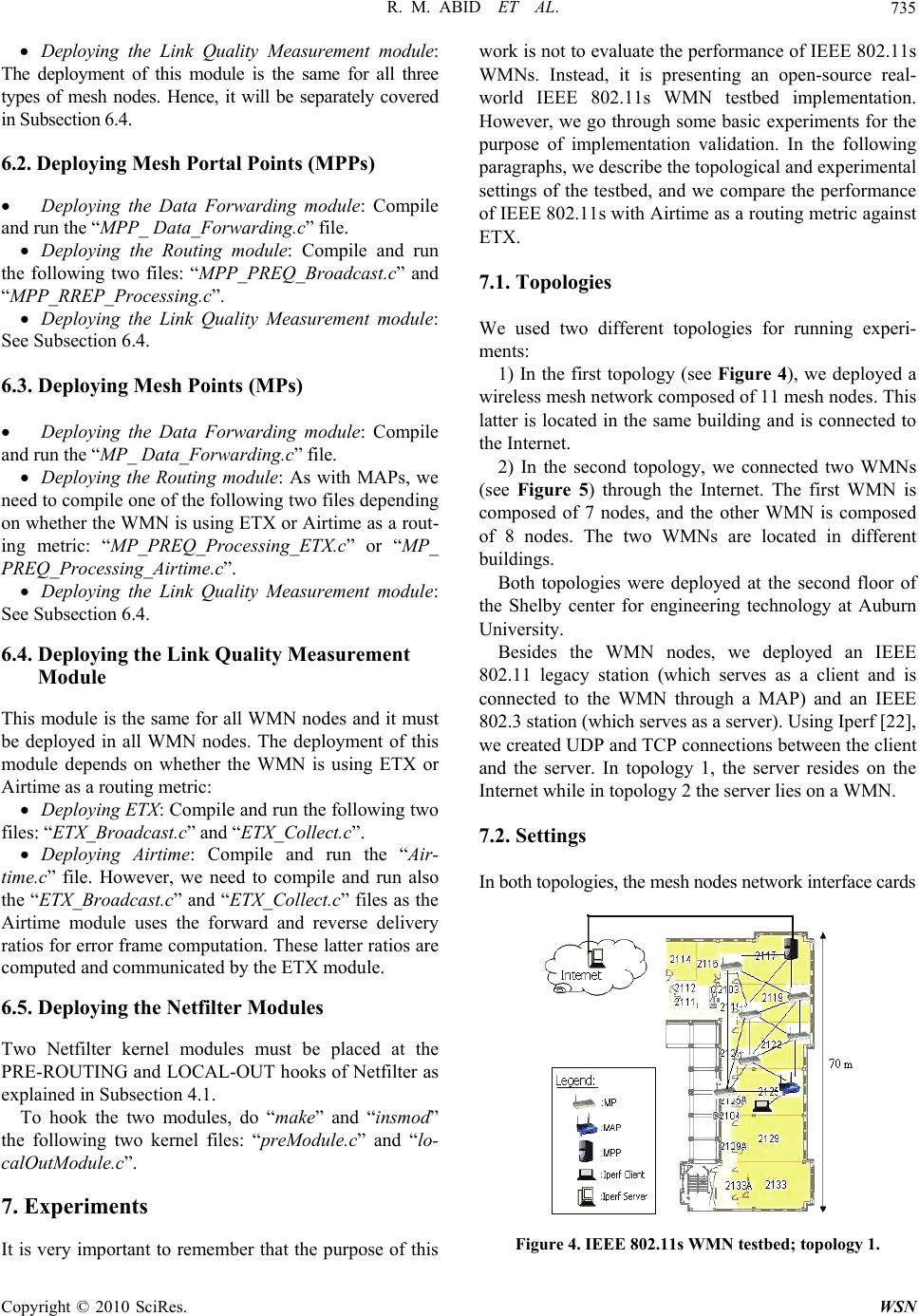 R. M. ABID ET AL. Copyright © 2010 SciRes. WSN 735 Deploying the Link Quality Measurement module: The deployment of this module is the same for all three types of mesh nodes. Hence, it will be separately covered in Subsection 6.4. 6.2. Deploying Mesh Portal Points (MPPs) Deploying the Data Forwarding module: Compile and run the “MPP_ Data_Forwarding.c” file. Deploying the Routing module: Compile and run the following two files: “MPP_PREQ_Broadcast.c” and “MPP_RREP_Processing.c”. Deploying the Link Quality Measurement module: See Subsection 6.4. 6.3. Deploying Mesh Points (MPs) Deploying the Data Forwarding module: Compile and run the “MP_ Data_Forwarding.c” file. Deploying the Routing module: As with MAPs, we need to compile one of the following two files depending on whether the WMN is using ETX or Airtime as a rout- ing metric: “MP_PREQ_Processing_ETX.c” or “MP_ PREQ_Processing_Airtime.c”. Deploying the Link Quality Measurement module: See Subsection 6.4. 6.4. Deploying the Link Quality Measurement Module This module is the same for all WMN nodes and it must be deployed in all WMN nodes. The deployment of this module depends on whether the WMN is using ETX or Airtime as a routing metric: Deploying ETX: Compile and run the following two files: “ETX_Broadcast.c” and “ETX_Collect.c”. Deploying Airtime: Compile and run the “Air- time.c” file. However, we need to compile and run also the “ETX_Broadcast.c” and “ETX_Collect.c” files as the Airtime module uses the forward and reverse delivery ratios for error frame computation. These latter ratios are computed and communicated by the ETX module. 6.5. Deploying the Netfilter Modules Two Netfilter kernel modules must be placed at the PRE-ROUTING and LOCAL-OUT hooks of Netfilter as explained in Subsection 4.1. To hook the two modules, do “make” and “insmod” the following two kernel files: “preModule.c” and “lo- calOutModule.c”. 7. Experiments It is very important to remember that the purpose of this work is not to evaluate the performance of IEEE 802.11s WMNs. Instead, it is presenting an open-source real- world IEEE 802.11s WMN testbed implementation. However, we go through some basic experiments for the purpose of implementation validation. In the following paragraphs, we describe the topological and experimental settings of the testbed, and we compare the performance of IEEE 802.11s with Airtime as a routing metric against ETX. 7.1. Topologies We used two different topologies for running experi- ments: 1) In the first topology (see Figure 4), we deployed a wireless mesh network composed of 11 mesh nodes. This latter is located in the same building and is connected to the Internet. 2) In the second topology, we connected two WMNs (see Figure 5) through the Internet. The first WMN is composed of 7 nodes, and the other WMN is composed of 8 nodes. The two WMNs are located in different buildings. Both topologies were deployed at the second floor of the Shelby center for engineering technology at Auburn University. Besides the WMN nodes, we deployed an IEEE 802.11 legacy station (which serves as a client and is connected to the WMN through a MAP) and an IEEE 802.3 station (which serves as a server). Using Iperf [22], we created UDP and TCP connections between the client and the server. In topology 1, the server resides on the Internet while in topology 2 the server lies on a WMN. 7.2. Settings In both topologies, the mesh nodes network interface cards Figure 4. IEEE 802.11s WMN testbed; topology 1. 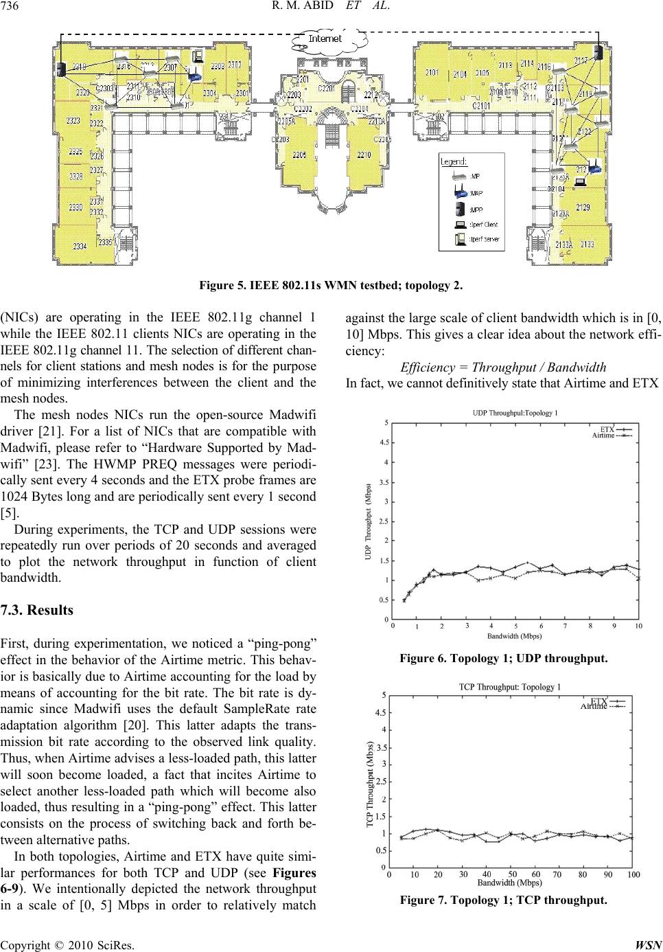 R. M. ABID ET AL. 736 Figure 5. IEEE 802.11s WMN testbed; topology 2. (NICs) are operating in the IEEE 802.11g channel 1 while the IEEE 802.11 clients NICs are operating in the IEEE 802.11g channel 11. The selection of different chan- nels for client stations and mesh nodes is for the purpose of minimizing interferences between the client and the mesh nodes. The mesh nodes NICs run the open-source Madwifi driver [21]. For a list of NICs that are compatible with Madwifi, please refer to “Hardware Supported by Mad- wifi” [23]. The HWMP PREQ messages were periodi- cally sent every 4 seconds and the ETX probe frames are 1024 Bytes long and are periodically sent every 1 second [5]. During experiments, the TCP and UDP sessions were repeatedly run over periods of 20 seconds and averaged to plot the network throughput in function of client bandwidth. 7.3. Results First, during experimentation, we noticed a “ping-pong” effect in the behavior of the Airtime metric. This behav- ior is basically due to Airtime accounting for the load by means of accounting for the bit rate. The bit rate is dy- namic since Madwifi uses the default SampleRate rate adaptation algorithm [20]. This latter adapts the trans- mission bit rate according to the observed link quality. Thus, when Airtime advises a less-loaded path, this latter will soon become loaded, a fact that incites Airtime to select another less-loaded path which will become also loaded, thus resulting in a “ping-pong” effect. This latter consists on the process of switching back and forth be- tween alternative paths. In both topologies, Airtime and ETX have quite simi- lar performances for both TCP and UDP (see Figures 6-9). We intentionally depicted the network throughput in a scale of [0, 5] Mbps in order to relatively match against the large scale of client bandwidth which is in [0, 10] Mbps. This gives a clear idea about the network effi- ciency: Efficiency = Throughput / Bandwidth In fact, we cannot definitively state that Airtime and ETX Figure 6. Topology 1; UDP throughput. Figure 7. Topology 1; TCP throughput. C opyright © 2010 SciRes. WSN 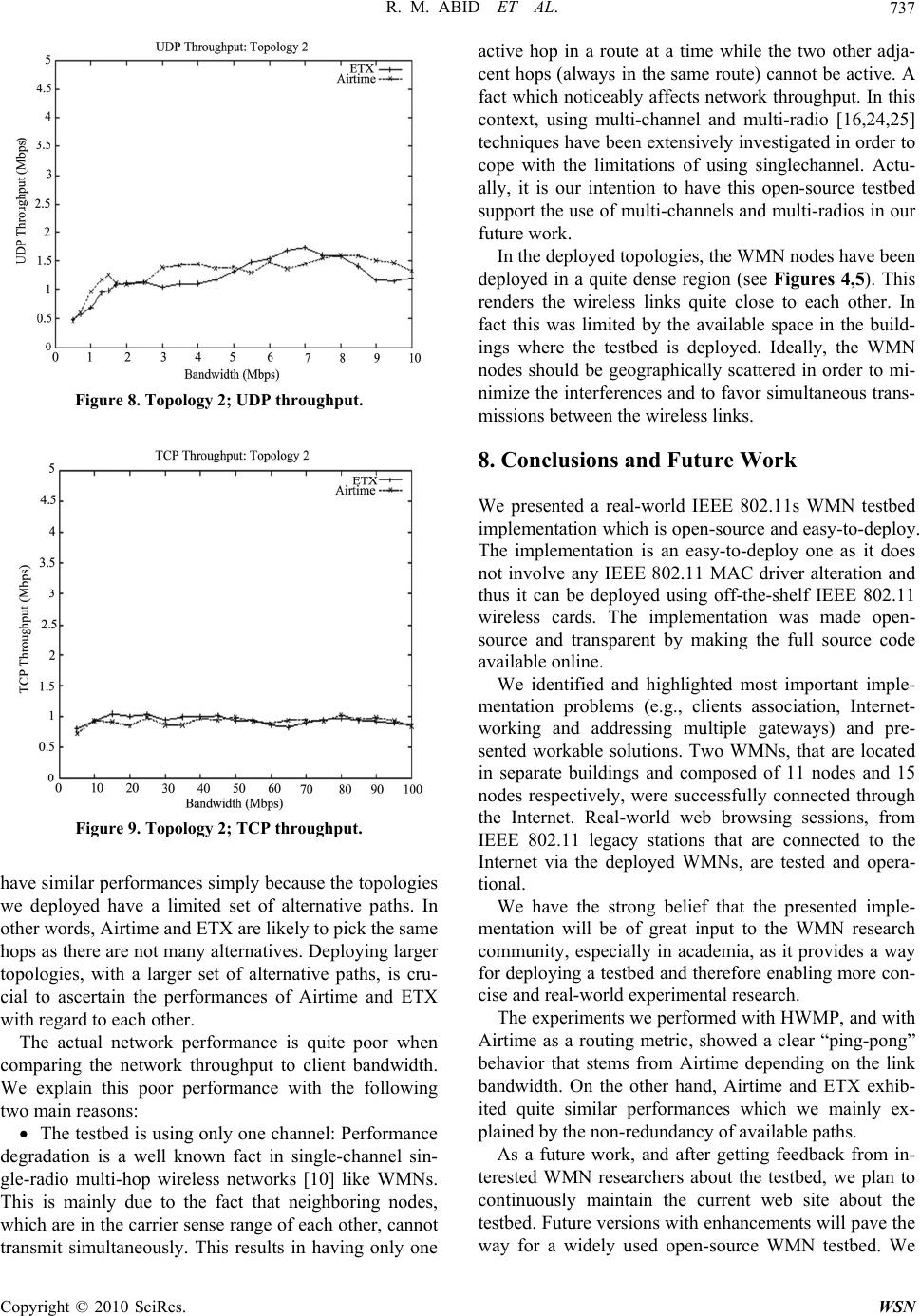 R. M. ABID ET AL.737 Figure 8. Topology 2; UDP throughput. Figure 9. Topology 2; TCP throughput. have similar performances simply because the topologies we deployed have a limited set of alternative paths. In other words, Airtime and ETX are likely to pick the same hops as there are not many alternatives. Deploying larger topologies, with a larger set of alternative paths, is cru- cial to ascertain the performances of Airtime and ETX with regard to each other. The actual network performance is quite poor when comparing the network throughput to client bandwidth. We explain this poor performance with the following two main reasons: The testbed is using only one channel: Performance degradation is a well known fact in single-channel sin- gle-radio multi-hop wireless networks [10] like WMNs. This is mainly due to the fact that neighboring nodes, which are in the carrier sense range of each other, cannot transmit simultaneously. This results in having only one active hop in a route at a time while the two other adja- cent hops (always in the same route) cannot be active. A fact which noticeably affects network throughput. In this context, using multi-channel and multi-radio [16,24,25] techniques have been extensively investigated in order to cope with the limitations of using singlechannel. Actu- ally, it is our intention to have this open-source testbed support the use of multi-channels and multi-radios in our future work. In the deployed topologies, the WMN nodes have been deployed in a quite dense region (see Figures 4,5). This renders the wireless links quite close to each other. In fact this was limited by the available space in the build- ings where the testbed is deployed. Ideally, the WMN nodes should be geographically scattered in order to mi- nimize the interferences and to favor simultaneous trans- missions between the wireless links. 8. Conclusions and Future Work We presented a real-world IEEE 802.11s WMN testbed implementation which is open-source and easy-to-deploy. The implementation is an easy-to-deploy one as it does not involve any IEEE 802.11 MAC driver alteration and thus it can be deployed using off-the-shelf IEEE 802.11 wireless cards. The implementation was made open- source and transparent by making the full source code available online. We identified and highlighted most important imple- mentation problems (e.g., clients association, Internet- working and addressing multiple gateways) and pre- sented workable solutions. Two WMNs, that are located in separate buildings and composed of 11 nodes and 15 nodes respectively, were successfully connected through the Internet. Real-world web browsing sessions, from IEEE 802.11 legacy stations that are connected to the Internet via the deployed WMNs, are tested and opera- tional. We have the strong belief that the presented imple- mentation will be of great input to the WMN research community, especially in academia, as it provides a way for deploying a testbed and therefore enabling more con- cise and real-world experimental research. The experiments we performed with HWMP, and with Airtime as a routing metric, showed a clear “ping-pong” behavior that stems from Airtime depending on the link bandwidth. On the other hand, Airtime and ETX exhib- ited quite similar performances which we mainly ex- plained by the non-redundancy of available paths. As a future work, and after getting feedback from in- terested WMN researchers about the testbed, we plan to continuously maintain the current web site about the testbed. Future versions with enhancements will pave the way for a widely used open-source WMN testbed. We Copyright © 2010 SciRes. WSN 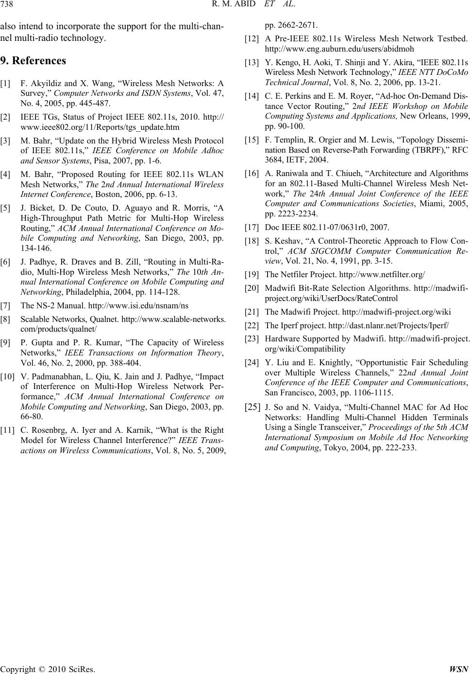 R. M. ABID ET AL. Copyright © 2010 SciRes. WSN 738 also intend to incorporate the support for the multi-chan- nel multi-radio technology. 9. References [1] F. Akyildiz and X. Wang, “Wireless Mesh Networks: A Survey,” Computer Networks and ISDN Systems, Vol. 47, No. 4, 2005, pp. 445-487. [2] IEEE TGs, Status of Project IEEE 802.11s, 2010. http:// www.ieee802.org/11/Reports/tgs_update.htm [3] M. Bahr, “Update on the Hybrid Wireless Mesh Protocol of IEEE 802.11s,” IEEE Conference on Mobile Adhoc and Sensor Systems, Pisa, 2007, pp. 1-6. [4] M. Bahr, “Proposed Routing for IEEE 802.11s WLAN Mesh Networks,” The 2nd Annual International Wireless Internet Conference, Boston, 2006, pp. 6-13. [5] J. Bicket, D. De Couto, D. Aguayo and R. Morris, “A High-Throughput Path Metric for Multi-Hop Wireless Routing,” ACM Annual International Conference on Mo- bile Computing and Networking, San Diego, 2003, pp. 134-146. [6] J. Padhye, R. Draves and B. Zill, “Routing in Multi-Ra- dio, Multi-Hop Wireless Mesh Networks,” The 10th An- nual International Conference on Mobile Computing and Networking, Philadelphia, 2004, pp. 114-128. [7] The NS-2 Manual. http://www.isi.edu/nsnam/ns [8] Scalable Networks, Qualnet. http://www.scalable-networks. com/products/qualnet/ [9] P. Gupta and P. R. Kumar, “The Capacity of Wireless Networks,” IEEE Transactions on Information Theory, Vol. 46, No. 2, 2000, pp. 388-404. [10] V. Padmanabhan, L. Qiu, K. Jain and J. Padhye, “Impact of Interference on Multi-Hop Wireless Network Per- formance,” ACM Annual International Conference on Mobile Computing and Networking, San Diego, 2003, pp. 66-80. [11] C. Rosenbrg, A. Iyer and A. Karnik, “What is the Right Model for Wireless Channel Interference?” IEEE Trans- actions on Wireless Communications, Vol. 8, No. 5, 2009, pp. 2662-2671. [12] A Pre-IEEE 802.11s Wireless Mesh Network Testbed. http://www.eng.auburn.edu/users/abidmoh [13] Y. Kengo, H. Aoki, T. Shinji and Y. Akira, “IEEE 802.11s Wireless Mesh Network Technology,” IEEE NTT DoCoMo Technical Journal, Vol. 8, No. 2, 2006, pp. 13-21. [14] C. E. Perkins and E. M. Royer, “Ad-hoc On-Demand Dis- tance Vector Routing,” 2nd IEEE Workshop on Mobile Computing Systems and Applications, New Orleans, 1999, pp. 90-100. [15] F. Templin, R. Orgier and M. Lewis, “Topology Dissemi- nation Based on Reverse-Path Forwarding (TBRPF),” RFC 3684, IETF, 2004. [16] A. Raniwala and T. Chiueh, “Architecture and Algorithms for an 802.11-Based Multi-Channel Wireless Mesh Net- work,” The 24th Annual Joint Conference of the IEEE Computer and Communications Societies, Miami, 2005, pp. 2223-2234. [17] Doc IEEE 802.11-07/0631r0, 2007. [18] S. Keshav, “A Control-Theoretic Approach to Flow Con- trol,” ACM SIGCOMM Computer Communication Re- view, Vol. 21, No. 4, 1991, pp. 3-15. [19] The Netfiler Project. http://www.netfilter.org/ [20] Madwifi Bit-Rate Selection Algorithms. http://madwifi- project.org/wiki/UserDocs/RateControl [21] The Madwifi Project. http://madwifi-project.org/wiki [22] The Iperf project. http://dast.nlanr.net/Projects/Iperf/ [23] Hardware Supported by Madwifi. http://madwifi-project. org/wiki/Compatibility [24] Y. Liu and E. Knightly, “Opportunistic Fair Scheduling over Multiple Wireless Channels,” 22nd Annual Joint Conference of the IEEE Computer and Communications, San Francisco, 2003, pp. 1106-1115. [25] J. So and N. Vaidya, “Multi-Channel MAC for Ad Hoc Networks: Handling Multi-Channel Hidden Terminals Using a Single Transceiver,” Proceedings of the 5th ACM International Symposium on Mobile Ad Hoc Networking and Computing, Tokyo, 2004, pp. 222-233.
|