Journal of Surface Engineered Materials and Advanced Technology, 2013, 3, 106-115
http://dx.doi.org/10.4236/jsemat.2013.31A015 Published Online February 2013 (http://www.scirp.org/journal/jsemat)
High Temperature Sintering and Oxidation Behavior in
Plasma Sprayed TBCs [Single Splat Studies] Paper
1—Role of Heat Treatment Variations
Swarnima Deshpande
Center for Thermal Spray Research, Department of Materials Science and Engineering, State University of New York at Stony Brook,
New York, USA.
Email: swarnima_d@yahoo.com
Received December 1st, 2012; revised December 31st, 2012; accepted January 7th, 2013
ABSTRACT
The TBC system is examined with regards to its response to thermal exposure at high temperature. It has been estab-
lished before that the thermally grown oxide (TGO) layer that forms upon bond coat oxidation is the key factor deter-
mining the performance of the TBC system and/or its failure. However, characteristics of TGO growth, bond coat rum-
pling, principles govern ing failure of TBC systems and the various failure mechanisms have been studied extensively in
case of just super alloy with bond coat or with thick top coating. In this study super alloy/bond coat system with single
splats of YSZ instead of thick topcoat is analyzed in order to scrutinize the effect on the first layer of splats during
thermal exposure. The splats with microcracks are the building blocks of the top coat. The most important aspect of this
layer is the inherent inter-splat and intra-sp lat porosity which undergoes sintering during thermal exposure. The interac-
tions between the YSZ splats and the evolving TGO is directly linked to the presence or absence of bond coat oxidation.
Therefore the high temperature behavior of this system is analyzed with variations in heat treatment involving, tem-
perature, duration and enviro nment of thermal exposure.
Keywords: TBC; Bond Coat; Top Coat; Thermal Exposure; Vacuu m Environment; Oxidation; TGO Imperfections;
Sintering
1. Introduction
Thermal barrier coatings (TBCs) are employed in the
aerospace and power systems because they permit the
usage of higher operating temperatures and reduced cool-
ing air requirements and yet achieve higher efficiencies
and longer engine life thus providing high ripple effects
on energy conservation. High service temperatures, ex-
treme and cyclic stresses and harsh environmental condi-
tions are some of the concerns [1]. They experience di-
verse thermal histories which could be just isothermal
exposure or multiple thermal cycles depending on the
application [2].
The TBCs are a system consisting of a superalloy sub-
strate, an MCrAlY bond coat (BC)and a YSZ top coat
I(TC) applied on these.A thermally grown oxide (TGO),
typically α-alumina, is formed during heat treatment and/or
in service between the bond coat and the topcoat [3]. The
bond-coat alloy is an Al reservoir, enab ling α-alumina to
form in preference to other oxides.
The failure mechanisms involve the TGO, the TGO/BC
interface and the TBC. It has been surmised that these
mechanisms are activated primarily by the stress state
caused by the residual compression in the TGO even
when the failure occurs in the TBC layer itself.
The TGO is subject to thickening, as well as an elon-
gation strain associated with new oxide formation on the
internal grain boun daries [4]. Stud ies show that thickness
of TGO increases with thermal exposure and induces the
strain energy for the crack propagation during spallation
[3]. Numerous studies have been conducted to assess the
evolution of this bond coat oxidation during thermal ex-
posure of TBC systems [5-9]. Factors during HT that
affect durability have been considered [3,10]. Under iso-
thermal HT, the TGO yields and the stress remains at
yield, such that all of the growth strain results in thick-
ening of TGO without elongation. Conversely cycling,
introduces additional growth strain with associated elon-
gation of the TGO that undergoes cyclic enlargement.
Inherent surface roughness of plasma sprayed bond coats
i.e. preexisting undulations in the film initiate TGO in-
stabilities which manifest as regu lar, (relatively) long wave-
length undulations, referred to as “rumpling” or local-
ized penetration of the TGO into the bond-coat, in the
Copyright © 2013 SciRes. JSEMAT
High Temperature Sintering and Oxidation Behavior in Plasma Sprayed TBCs [Single Splat Studies]
Paper 1—Role of Heat Treatment Variations 107
Table 1. Deposition parameters for APS sprayed NiCrAlY
bond coat.
presence of a TBC layer, referred to as “ratcheting”.
TGO growth and TGO instabilities influence TBC be-
havior and failure. Effect of rumpling on TBC layer, if
present, is observed to be a delamination between TGO
and topcoat leading to subsequent failure [9].
However, characteristics of TGO growth, bond coat
rumpling, principles governing failure of TBC systems
and the various failure mechanisms have been studied
extensively in case of just superalloy with bond coat or
with thick top coating [7,8].
In this study superalloy/bond coat system with single
splats of YSZ instead of thick topcoat is analyzed. The
objectives are:
Understanding the influence of present YSZ layer on
the chemistry of bond coat oxidation.
Studying the interactions between the YSZ splats and
the evolving TGO.
Inspection of effects of bond coat oxidation on first
splat layer of topcoat. Single splats as opposed to
freestanding coatings include the splat/substrate in-
terfacial interaction. The morphological changes and
sintering of intrasplat cracks in the YSZ is directly
linked to the presence or absence of bond coat oxida-
tion.
2. Experimental Approach
NiCrAlY coatings were air plasma sprayed onto Inconel
718 superalloy substrates. The surfaces of these sub-
strates were then polished to a 0.05 micron finish using a
Buehler semi-automatic polisher. Single splats of YSZ
were collected on these bond coat surfaces in order to
conduct thermal exposure studies on the same. Splats
were collected on polished bond coat surface so as to
eliminate ratcheting instabilities that could arise due to
initial undulations on BC/TBC interface.
Processing conditions used for the NiCrAlY bond
coats and the YSZ splats are given below in Tables 1 and
2 respectively.
Thermal exposure behavior of these splats in air was
studied using a Thermolyne 1400 box furnace, to see
effect of temperature and duration. Temperatures used
were in the range of 1100˚C to 1300˚C and durations
were 2 to 24 hrs. Only isothermal heat treatments were
employed to eliminate cyclic TGO elongation effects.
Long-term exposure to high temperature is thought to
reduce mismatch stress in the bond coat by relaxation
and creep [Ref. from 9] thus resulting in a very long rum-
pling wavelength and making it impossible to observe
the rumpling process. As such for this sing le splat study,
shorter exposure times were considered for isothermal
heat treatments to avoid complete spallation or failure.
Gun Sulzer F4MB
Gun voltage 68 V
Gun current 500 A
Primary gas (Ar) 50 SLPM
Secondary gas (H2) 10 SLPM
Carrier gas(Ar) 3 SLPM
Spray distance 120 mm
Powder Feed rate 40 g/min
Table 2. Deposition parameters for APS sprayed YSZ splats
[Metco 204NS].
Gun PT-F4MB
Gun voltage 65 V
Gun current 650 A
Primary gas (Ar) 40 SLPM
Secondary gas (H2) 8 SLPM
Carrier gas (Ar) 3 SLPM
Spray distance 100 mm
Powder Feed rate 10 g/min
Gun traverse speed 10 mm/sec
Substrate rotational speed 160 rpm
see changes in crack network, surface roughness, and
splat lifting/spalling. A comparison of splat cross-sec-
tions was made using SEM (Leo 1550, FEG) to observe
splat dimensions, microcrack sintering and effect of TGO
growth after HT. Back-scattered imaging was employed
and Energy Dispersive Spectrometry (EDS) gave ele-
mental composition. Atomic Force Microscopy (AFM)
was employed to quantify surface roughness of splats.
Cross-section (CS) samples were prepared by covering
the single splats with glass slide, Figure 1, and then pol-
ishing using the SEM T-tool of the tripod polisher.
3. Results and Discussion
The sintering stud y of sing le splats on bond-co at is i m-
portant because in case of single splats the factors intro-
duced by TBC coating are minimal and failure can be
more related to the bond-coat chemistry and microstruc-
ture which upon thermal exposure chang es by interdiffu-
sion with the substrate and upon thickening of the ther-
mally grown ox ide (TGO) . The appearan ce of failur e and
sites of failure can be determined more stochastically [11].
Particular splats were identified and the top surface
microstructures before and after HT were compared to Single splats of YSZ sprayed onto polished surfaces of
Copyright © 2013 SciRes. JSEMAT
High Temperature Sintering and Oxidation Behavior in Plasma Sprayed TBCs [Single Splat Studies]
Paper 1—Role of Heat Treatment Variations
Copyright © 2013 SciRes. JSEMAT
108
Figure 1. Cross-section sample preparation of single splats on bond coat surface.
MCrAlY bond coats were sub jected to variou s heat treat-
ments. Their top surface microstructures and cross-sec-
tions were analyzed before and after Heat Tr eatment (HT)
as described in the previous section.
In order to understand the influence of TGO growth
and thickening on the first layer of splats, this system of
splatbond coatsubstrate was thermally exposed to
different temperatures and for different durations.
3.1. TGO Growth—Effect of Heat Treatment
Temperature
YSZ splats on bond coated substrate were subjected to a
2 hr heat treatment in air (isochronal) at different tem-
peratures: 1100˚C, 1200˚C and 1300˚C. Particular splats
were identified and their top surface microstructures, at
exact locations, in the as-sprayed and heat treated condi-
tion are shown in Figures 2(a)-(c) for the three tempera-
tures respectively.
In Figure 2(a), it is seen that after HT at 1100˚C, the
overall crack network between the as-sprayed and the
heat treated splat seems unchanged. The grain size does
not seem to have altered either.
According to Figure 2(b), after HT at 1200˚C, the as-
sprayed and heat-treated splats still show same overall
crack network. However, some outward oxide growth
from the bond coat is now visible at the larger micro-
cracks as shown by the circle marks. Finer microcracks
have also started sintering as indicated by the arrows.
These effects are even more pronounced after the
1300˚C HT, Figure 2(c).
More of the fine microcracks are seen to have sintered
and the entire microcrack network is now lined with the
oxide growth from below. These grains growing outward
through the microcracks were analyzed using EDS and
indicated Ni and O peaks. These phenomena are sche-
matically illustrated in Figure 3.
3.1.1. NiO Outgrowth Outlining Crack Network on
Splat Surface
APS NiCrAlY bond coat microstructure (Figure 4) con-
tains internal oxide chunks of alumina. These regions
may be locally depleted of aluminum. Microcracks in
splats are seen to coincide with oxid e points in the bond-
coat, Figure 4.
Several studies have shown that oxygen diffusion
through TGO along grain boundaries causes more TGO
growth at these boundaries [4,5,8]. Similarly at these micro-
crack positions, there is a path for oxygen to reach a BC
area that is locally depleted of free aluminum. As such,
other oxides could form at these microcrack positions.
Supporting Observation
In some circumstances, as activity of Oxygen at the
interface increases, the solubilities of Ni and Cr (and Fe
when present) in the Al2O3 also increase. This condition
can result in outward diffusion of cations through the
TGO. Upon encountering higher oxygen activities, these
cations can form new oxide phases. For e.g. in regions
between the TGO and the TBC, the thermodynamics and
kinetics are such that spinel formation is allowed [8].
3.1.2. Sintering of Fine Microcracks
A study by Thompson et al. speculates regarding sub-
processes occurring at a splat level during sintering, as
shown in Figure 5. The as-sprayed microstructure (a)
incorporates three types of pores. Stage I (b) involves
healing of interlamellar porosity, where the separation in
the material is very small. While at longer times and at
higher temperatures, Stage II (c) occurs by micro-crack
healing [3].
Since we are dealing with single splats, we cannot ob-
serve the stage I sintering. But incidences of sintering of
finer microcracks are seen to increase as HT temperature
increases. This is in agreement with the observation of
the above study.
3.2. TGO Thickening—Effect of Heat Treatment
Duration
YSZ splat samples were subjected to an isothermal heat
treatment in air at 1100˚C for different durations: 2 hr, 8
hr and 24 hr. Figure 6 shows thermally grown oxide
High Temperature Sintering and Oxidation Behavior in Plasma Sprayed TBCs [Single Splat Studies]
Paper 1—Role of Heat Treatment Variations 109
As-sprayed splat After 2hr HT in Air
(a)
As-sprayed splat After 2hr HT in Air
Ni
Ni
ONi
Ni
O
(b)
Copyright © 2013 SciRes. JSEMAT
High Temperature Sintering and Oxidation Behavior in Plasma Sprayed TBCs [Single Splat Studies]
Paper 1—Role of Heat Treatment Variations
110
As-sprayed splat After 2hr HT in Air
(c)
Figure 2. (a) Splat exposed to 1100˚C; (b) Splat exposed to 1200˚C; (c) Splat exposed to 1300˚C.
Microcrack sintering
Oxide growing out
of microcracks
Figure 3. Isochronal HT in air—effect of temp (schematic).
O K
Al K
Ni L
O K
Al K
Ni L
Figure 4. Microcracks coinciding with oxide points.
Copyright © 2013 SciRes. JSEMAT
High Temperature Sintering and Oxidation Behavior in Plasma Sprayed TBCs [Single Splat Studies]
Paper 1—Role of Heat Treatment Variations
Copyright © 2013 SciRes. JSEMAT
111
Figure 5. Schematic representation of the proposed sintering mechanism occurring at high temperature [Ref 3: J. A.Thompson,
W. Ji, T. Klocker and T. W.Clyne].
As-sprayed ZrO2 splat on bond coat surf ace
TGO formed at bond coat/splat in terface aft er 24 h @ 1100˚C
Figure 6. Interface between bond coat and ZrO 2 splats (shown as composite images).
layer formed at the interface between bond coat and top
coat after 24 hr HT in air.
Splats are imaged at particular locations and their top
surface microstructures in the as-sprayed and heat-treated
condition are compared in Figures 7(a)-(c) for the three
HT times respectively.
Figure 7(a) shows that after a 2hr HT at 1100˚C the
overall crack network has not changed significantly. The
columnar grains in the splat appear to have been pushed
slightly upwards in so me areas. Such regions are marked
by square marks.
As seen in Figure 7(b) below, after an 8 hr HT, the
microcrack network still remain s unchanged between the
as-sprayed and the heat-treated splats. Most of the fine
microcracks are also still present. However the top sur-
face of the heat-treated splat appears much rougher com-
pared to the top surface of the as-sprayed splat. Square
marks denote this roughening. This has been quantified
using Atomic Force Microscopy (AFM). Wave patterns
depicting the roughness are obtained using section analy-
sis. Mean Roughness analysis over a given area measures
the value of roughness as Ra = 12 nm for the as-sprayed
splat surface and Ra = 153 nm for the heat-treated splat
surface. Apart from this, top surface as well as cross-
section images show a few instances of oxide growth
through microcracks (circle marks) as described in the
previous section.
From Figure 7(c) below, it is seen that even a 24 hr
HT at 1100˚C does not cause the overall microcrack net-
work to change or fine microcracks to sinter. More in-
stances of outward oxide growth as marked by circle
marks are now visible even at 1100˚C because of longer
HT duration. Thus this outward oxide growth is en-
hanced by an increase in HT temperature as well as an
increase in duration of HT.
Once again splat surface after HT becomes rougher
because of lifting of columnar grains in some regions. An
examination of cross-section samples revealed that this is
probably due to oxide growth over the bond coat (TGO)
and its thickness imperfections.
A comparison of Figures 7(a)-(c) shows how the TG O
thickness gradually increases with HT duration. This
High Temperature Sintering and Oxidation Behavior in Plasma Sprayed TBCs [Single Splat Studies]
Paper 1—Role of Heat Treatment Variations
112
After HT @ 1100˚C As-sprayed splat
Interface between NiCrAlY coating
and YSZ splats before HT
(a)
As-sprayed splat After HT @ 1100 C
Outward oxide growth from
bond coat oxide as seen on
top surface (green arrow)
1.3
m
1.1 m
Alumina Chromia
AFM (Section Analysis and
Mean Roughness Analysis)
After HT @ 1100 C
As-sprayed splat
Ra = 153.08 nm
Ra = 11.852 nm
(b)
Copyright © 2013 SciRes. JSEMAT
High Temperature Sintering and Oxidation Behavior in Plasma Sprayed TBCs [Single Splat Studies]
Paper 1—Role of Heat Treatment Variations 113
After HT in Air @ 1100 C
As-sprayed splat
T
hermally grown oxide (TGO)
consisting of alumina and
chromia layers
Aluminum Oxide
2.7
m
As-sprayed splat
Cr
O
Cr
O
Cr
OAl
Cr
OAl
Chromia Layer
(c)
Figure 7. (a) Splat exposed for 2 hr; (b) Splat exposed for 8 hr; (c) Splat exposed for 24 hr.
TGO layer is mainly constituted by Alumina since Al in
the bond coat is preferably oxidized but at some places
Chromia is also formed as disclosed by EDS. Previous
studies also show that other oxides occur in isolated do-
mains within the TBC next to the TGO and h ave a ligh ter
gray contrast. These are typically spinels comprising oxi-
des of Cr/Ni/Co often with associated internal porosity
[11]. Studies have shown that spinels when formed also
act as preferential sites for failure [11]. Reason might be
that the interfacial fracture resistances of the TBC/
α-chromia and the TBC/spinel interfaces are lower than
that of the TBC/α-alumina interface originally present
[12].
Thickness imperfections in TGO enlarge in regions
where O2-diffusivity through TGO is ex ceptionally large
i.e. at locations where TGO contains oxides other than
alumina [8]. These TGO undulations must then push the
grains in the sp lats upward and cause sp lat lifting or may
be spalling. This explains the increase of surface rough-
ness.
3.3. Elimination of Bond Coat OxidationEffect
of Heat Treatment Environment
In order to isolate the effect of bond coat oxidation, heat
treatment was conducted in vacuum thus eliminating it.
Thermal cycling studies of TBC systems have shown
how bond coat oxidation leads to phenomena such as
ratcheting and influences TBC behavior and failure [5-9].
The role of the TGO layer that grows between bond coat
and TBC during thermal cycling is of significance. In
order to assess this, heat treatments were also conducted
in vacuum so as to eliminate oxidation and see how the
behavior differs with changes in HT environment.
Figure 8 shows an as-sprayed YSZ splat subjected to
an intermediate vacuum heat treatment at 1100˚C for 2
hrs before exposure to the 24hr air HT at 1100˚C. After
Copyright © 2013 SciRes. JSEMAT
High Temperature Sintering and Oxidation Behavior in Plasma Sprayed TBCs [Single Splat Studies]
Paper 1—Role of Heat Treatment Variations
114
As-sprayed splat
0.17 m
0.52 m0.48 m
0.45 m
After 2 hr HT in Vacuum After 24 hr HT in Air
As-sprayed Vacuum 2hr at 1100Air 24 hr at 1100
Figure 8. As-sprayed splat exposed for 2 hr in Vac exposed for 24 hr @ 1100 C in air.
the intermediate vacuum HT of 2 hr at 1100˚C, the over-
all microcrack network appears unaltered as seen in the
top surface microstructures. The oxide grain growth
through microcracks or the splat surface roughening are
however, not visible.
A comparison is made between this and the as-sprayed
splat that directly underwent the 24 hr air HT, as shown
in Figure 7(c). As discussed earlier in section 3.2, the
splats directly exposed to the 24 hr Air HT at 1100˚C
showed instances of outward oxide growth through mi-
crocracks (circle marks) and surface roughening due to
splat lifting (square marks).
However, the splats with intermediate vacuum HT as
shown in Figure 8 when thermally treated in air for 24 hr
showed no signs of grain growth through microcracks or
of upward lifting of grains. Additionally, most fine mi-
crocracks are seen to have sintered as marked by arrows.
The cross-section images show that microcrack widths
are much reduced compared to the as-sprayed splat. TGO
growth does occur in the subsequent air HT but the out-
ward oxide growth is curtailed probably because the in-
termediate vacuum treatment started the sintering or
sealing of most microcracks from their bottom end. This
may be related to the increase in lattice spacing that was
observed by Thornton et al. [13] when a TBC coating
was heat treated in vacuum. In vacuum, there is no oxy-
gen to replace that lost from zirconia in the formation of
bond coat oxide and less oxygen appears to cause larger
lattice spacing [13].
Thus the overall sintering behavior is notably altered
by a change in heat treatment environment.
4. Summary and Conclusions
The high temperature behavior of a TBC system is in-
vestigated using single splats of YSZ on MCrAlY bond
coat surface instead of freestanding thick YSZ coatings,
in order to integrate the effects of splat-substrate interfa-
cial interaction and bond coat oxidation at a fundamental
level. In case of single splats sprayed on polished bond-
coat surface, there are no preexisting undulations (inter-
facial imperfections), and also no influence of thick top
coating. Phenomena such as ratcheting and rumpling
which have been analyzed in other studies with thick
topcoats are not observed here. These would have drastic
spallation effects in case of single splats and hence have
been excluded by the u sag e of po lished bond co at sur face
and short thermal exposures. Effects of thermal treat-
ment are attributable to the thickening of the thermally
grown oxide (TGO) layer and the initial bond coat mi-
crostructure.
The TGO layer grows and thickens with increasing
temperature and duration of thermal exposure. Ther-
mal treatment temperature is seen to have a more sig-
nificant influence on microcracks sintering than the
duration of thermal exposure.
Environment during thermal exposure also has a re-
Copyright © 2013 SciRes. JSEMAT
High Temperature Sintering and Oxidation Behavior in Plasma Sprayed TBCs [Single Splat Studies]
Paper 1—Role of Heat Treatment Variations 115
markable impact. Even a short intermediate vacuum
treatment changes the high temperature behavior ob-
served otherwise during long air treatment and causes
sintering of most fine microcracks. Thus sintering of
microcracks is directly influenced by bond coat oxi-
dation.
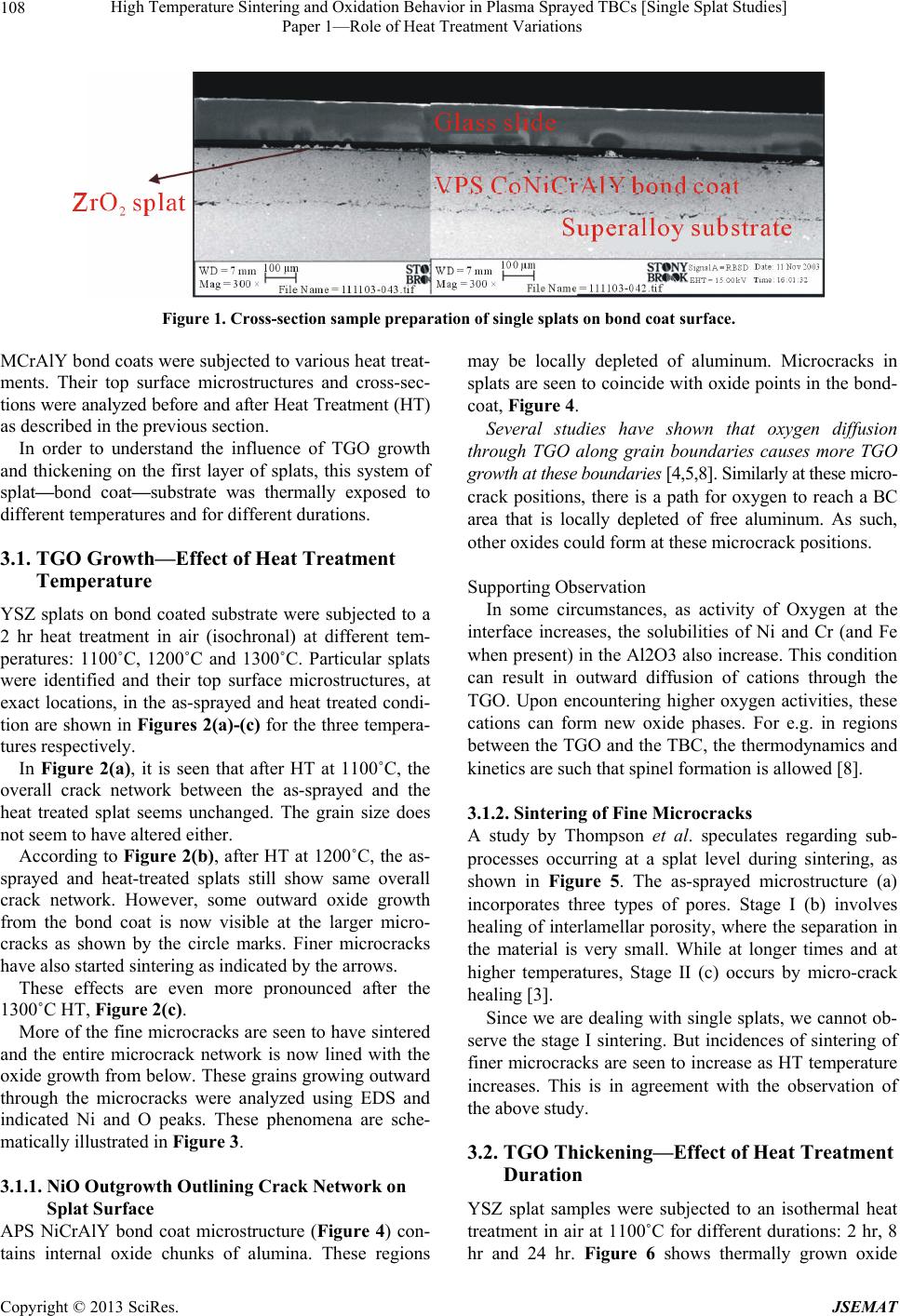
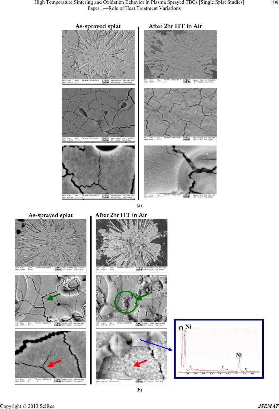
Microcracks in as-sprayed splats coincide with inter-
nal oxide positions within bond coat. A path is thus
provided for oxygen to reach a bond coat area that is
locally depleted of aluminum. As such, other oxides
such as NiO form locally at these microcracks. Che-
mical changes occur in the bond coat oxidation due to
presence of the YSZ splats on top.
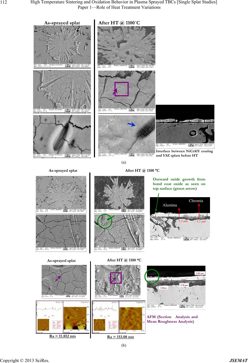
Outward oxide growth into microcracks increases
with heat treatment temperature as well as time.
Longer thermal treatment durations cause further Al
depletion within bond coat leading to formation of
oxides other than α-alumina in the TGO, thereby cre-
ating thickness imperfections in the TGO at some lo-
cations. These TGO undulations are observed to push
grains in the splats upward and induce splat lift-
ing/spalling. Interaction between evolving TGO and
YSZ top coat is thus apparent in the form of splat
surface roughening.
The distinctions of TGO formation and interactions
with YSZ as a function of initial YSZ splat layer (mor-
phology, purity) and initial bond coat microstructure
(processing condition s) will be addressed in a subseq uent
paper.
5. Acknowledgements
We would like to thank Glenn Bancke, AnirudhaVaidya
and Li Li (CTSR) for preparation of the specimens and
spraying diagnostics.
REFERENCES
[1] P. S. Mohanty, “Challenges in Thermal Spraying of Re-
fractory Materials,” Surface Engineering, Vol. 21, No. 1,
2005, pp. 1-4. doi:10.1179/174329405X36691
[2] A. G. Evans, “Thermal Barrier Coatings: Workshop Sum-
mary,” TBC Workshop, Irsee, 17-22 August 2003, pp. 17-
22.
[3] A. N. Khan and J. Lu, “Behavior of Air Plasma Sprayed
Thermal Barrier Coatings, Subject to Intense Thermal
Cycling,” Surface and Coatings Technology, Vol. 166,
No. 1, 2003, pp. 37-43.
doi:10.1016/S0257-8972(02)00740-5
[4] T. Xu, M. Y. He and A. G. Evans, “A Numerical As-
sessment of the durability of Thermal Barrier Systems
That Fail by Ratcheting of the Thermally Grown Oxide,”
Acta Materialia, Vol. 51, No. 13, 2003, pp. 3807-3820.
doi:10.1016/S1359-6454(03)00194-0
[5] A. M. Karlsson, J. W. Hutchinson and A. G. Evans, “The
Displacement of the Thermally Grown Oxide in Thermal
Barrier Systems upon Thermal Cycling,” Materials Sci-
ence and Engineering, Vol. 351, No. 1-2, 2003, pp. 244-
257. doi:10.1016/S0921-5093(02)00843-2
[6] M. Y. He, A. G. Evans and J. W. Hutchinson, “The Rat-
cheting of Compressed Thermally Grown Thin Films on
Ductile Substrates,” Acta Materialia, Vol. 48, No. 10,
2000, pp. 2593-2601.
doi:10.1016/S1359-6454(00)00053-7
[7] D. R. Mumm, A. G. Evans and I. T. Spitsberg, “Charac-
terization of a Cyclic Displacement Instability for a
Thermally Grown Oxide in a Thermal Barrier System,”
Acta Materialia, Vol. 49, No. 12, 2001, pp. 2329-2340.
doi:10.1016/S1359-6454(01)00071-4
[8] A. G. Evans, D. R. Mumm, J. W. Hutchinson, G. H. Mei-
er and F. S. Pettit, “Mechanisms Controlling the Du- ra-
bility of Thermal Barrier Coatings,” Progress in Mate-
rials Science, Vol. 46, No. 5, 2001, pp. 505-553.
doi:10.1016/S0079-6425(00)00020-7
[9] R. Panat, S. Zhang and K. J. Hsia, “Bond Coat Surface
Rumpling in Thermal Barrier Coatings,” Acta Materialia,
Vol. 51, No. 1, 2003, pp. 239-249.
doi:10.1016/S1359-6454(02)00395-6
[10] A. M. Karlsson and A. G. Evans, “A Numerical Model
for the Cyclic Instability of Thermally Grown Oxides in
Thermal Barrier Systems,” Acta Materialia, Vol. 49, No.
10, 2001, pp. 1793-1804.
doi:10.1016/S1359-6454(01)00073-8
[11] A. Rabiei and A. G. Evans, “Failure Mechanisms Associ-
ated with the Thermally Grown Oxide in Plasma Sprayed
Thermal Barrier Coatings,” Acta Materialia, Vol. 48, No.
15, 2000, pp. 3963-3976.
doi:10.1016/S1359-6454(00)00171-3
[12] E. A. G. Shillington and D. R. Clarke, “Spalling Failure
of a Thermal Barrier Coating Associated with Aluminum
Depletion in the Bond-Coat,” Acta Materialia, Vol. 47,
No. 4, 1999, pp. 1297-1305.
doi:10.1016/S1359-6454(98)00407-8
[13] J. Thornton, D. Cookson and E. Prescott, “The Measure-
ment of Strains within the Bulk of Aged and As-Sprayed
Thermal Barrier Coatings Using Synchrotron Radiation,”
Surface and Coatings Technology, Vol. 120-121, 1999,
96-102. doi:10.1016/S0257-8972(99)00340-0
Copyright © 2013 SciRes. JSEMAT