Paper Menu >>
Journal Menu >>
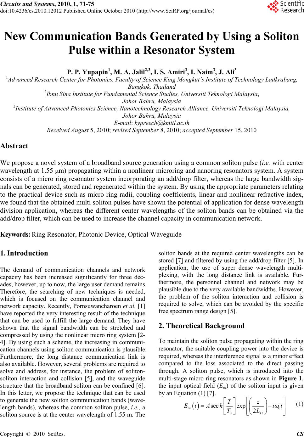 Circuits and Systems, 2010, 1, 71-75 doi:10.4236/cs.2010.12012 Published Online October 2010 (http://www.SciRP.org/journal/cs) Copyright © 2010 SciRes. CS New Communication Bands Generated by Using a Soliton Pulse within a Resonator System P. P. Yupapin1, M. A. Jalil2,3, I. S. Amiri3, I. Naim3, J. Ali3 1Advanced Research Center for Photonics, Faculty of Science King Mongkut’s Institute of Technology Ladkrabang, Bangkok, Thailand 2Ibnu Sina Institute for Fundamental Science Studies, Universiti Teknologi Malaysia, Johor Bahru, Malaysia 3Institute of Advanced Photonics Science, Nanotechnology Research Alliance, Universiti Teknologi Malaysia, Johor Bahru, Malaysia E-mail: kypreech@kmitl.ac.th Received August 5, 2010; revised September 8, 2010; accepted September 15, 2010 Abstract We propose a novel system of a broadband source generation using a common soliton pulse (i.e. with center wavelength at 1.55 m) propagating within a nonlinear microring and nanoring resonators system. A system consists of a micro ring resonator system incorporating an add/drop filter, whereas the large bandwidth sig- nals can be generated, stored and regenerated within the system. By using the appropriate parameters relating to the practical device such as micro ring radii, coupling coefficients, linear and nonlinear refractive index, we found that the obtained multi soliton pulses have shown the potential of application for dense wavelength division application, whereas the different center wavelengths of the soliton bands can be obtained via the add/drop filter, which can be used to increase the channel capacity in communication network. Keywords: Ring Resonator, Photonic Device, Optical Waveguide 1. Introduction The demand of communication channels and network capacity has been increased significantly for three dec- ades, however, up to now, the large user demand remains. Therefore, the searching of new techniques is needed, which is focused on the communication channel and network capacity. Recently, Pornsuwancharoen et al. [1] have reported the very interesting result of the technique that can be used to fulfill the large demand. They have shown that the signal bandwidth can be stretched and compressed by using the nonlinear micro ring system [2- 4]. By using such a scheme, the increasing in communi- cation channels using soliton communication is plausible. Furthermore, the long distance communication link is also available. However, several problems are required to solve and address, for instance, the problem of soliton- soliton interaction and collision [5], and the waveguide structure that the broadband soliton can be confined [6]. In this letter, we propose the technique that can be used to generate the new soliton communication bands (wave- length bands), whereas the common soliton pulse, i.e., a soliton source is at the center wavelength of 1.55 m. The soliton bands at the required center wavelengths can be stored [7] and filtered by using the add/drop filter [5]. In application, the use of super dense wavelength multi- plexing, with the long distance link is available. Fur- thermore, the personnel channel and network may be plausible due to the very available bandwidths. However, the problem of the soliton interaction and collision is required to solve, which can be avoided by the specific free spectrum range design [5]. 2. Theoretical Background To maintain the soliton pulse propagating within the ring resonator, the suitable coupling power into the device is required, whereas the interference signal is a minor effect compared to the loss associated to the direct passing through. A soliton pulse, which is introduced into the multi-stage micro ring resonators as shown in Figure 1, the input optical field (Ein) of the soliton input is given by an Equation (1) [7]. 0 0 secexp 2 in D Tz EtA hit TL (1)  P. P. YUPAPIN ET AL. Copyright © 2010 SciRes. CS 72 Figure 1. A broadband generation system. (a) a broadband source generation and a storage unit; (b) a soliton band selector, where Rs: ring radii, s: coupling coefficients, 41, 42: coupling losses, k61 and k61 are the add/drop coupling coefficients. where A and z are the optical field amplitude and propa- gation distance, respectively. T is a soliton pulse propa- gation time in a frame moving at the group velocity, T = t- 1*z, where 1 and 2 are the coefficients of the linear and second order terms of Taylor expansion of the pro- pagation constant. 2 02D LT is the dispersion length of the soliton pulse. To in equation is a soliton pulse propagation time at initial input. Where t is the soliton phase shift time, and he frequency shift of the soliton is ω0. This solution describes a pulse that keeps its tempo- ral width invariance as it propagates, and thus is called a temporal soliton. When a soliton peak intensity 2 20 /T is given, then o T is known. For the soliton pulse in the micro ring device, a balance should be achieved between the dispersion length (LD) and the nonlinear length (LNL = (1/ NL), where =n2*k0, is the length scale over which dispersive or nonlinear effects makes the beam becomes wider or narrower. For a soli- ton pulse, there is a balance between dispersion and nonlinear lengths, hence D NL LL. When light propagates within the nonlinear material (medium), the refractive index (n) of light within the medium is given by 2 02 0 (), eff n nn nInP A (2) where n and n are the linear and nonlinear refrac- tive indexes, respectively. I and P are the optical in- tensity and optical power, respectively. The effective mode core area of the device is given byeff A . For the micro ring and nano ring resonators, the effective mode core areas range from 0.50 to 0.1 m2 [8], where they found that fast light pulse can be slow down experimen- tally after input into the nano ring. When a soliton pulse is input and propagated within a micro ring resonator as shown in Figures 1(a) and (b), which consists of a series micro ring resonators. The resonant output is formed, thus, the normalized output of the light field is the ratio between the output and input fields (() out Etand )(tEin ) in each roundtrip, which can be expressed as 2 2 22 () () (1 (1)) (1) 1 (111)411sin() 2 out in Et Et x xx (3) The close form of Equation (3) indicates that a ring resonator in the particular case is very similar to a Fabry- Perot cavity, which has an input and output mirror with a field reflectivity, (1- ), and a fully reflecting mirror. is the coupling coefficient, and exp/2xL re- presents a roundtrip loss coefficient, 00 kLn and 2 2 N Lin kLn E are the linear and nonlinear phase shifts, 2/k is the wave propagation number in a vacuum. Where L and are a waveguide length and ( a ) ( b )  P. P. YUPAPIN ET AL. Copyright © 2010 SciRes. CS 73 linear absorption coefficient, respectively. In this work, the iterative method is introduced to obtain the results as shown in Equation (3), similarly, when the output field is connected and input into the other ring resonators. After the signals are multiplexed with the generated chaotic noise, then the chaotic cancellation is required by the individual user. To retrieve the signals from the cha- otic noise, we propose to use the add/drop device with the appropriate parameters. This is given in details as followings. The optical circuits of ring-resonator add/ drop filters for the throughput and drop port can be given by Equations (4) and (5), respectively [9]. 2 2 112 2 2 121 2 1211cos 1 11 1211cos t in L L n L L n E E ekL e eekL (4) 2 2 12 2 121 2 11 1211cos d in L L L n E E e eekL (5) where Et and Ed represents the optical fields of the throughput and drop ports respectively. eff kn is the propagation constant, eff n is the effective refractive index of the waveguide and the circumference of the ring is 2LR , here R is the radius of the ring. In the following, new parameters will be used for simplification: L is the phase constant. The chaotic noise cancel- lation can be managed by using the specific parameters of the add/drop device, which the required signals can be retrieved by the specific users. 1 and 1 are coupling coefficient of add/drop filters, 2/ n k is the wave propagation number for in a vacuum, and where the waveguide (ring resonator) loss is = 0.5 dBmm-1. The fractional coupler intensity loss is = 0.1. In the case of add/drop device, the nonlinear refractive index is ne- glected. 3. Results and Discussion In operation, the large bandwidth signal within the micro ring device can be generated by using a common soliton pulse input into the nonlinear micro ring resonator. This means that the broad spectrum of light can be generated after the soliton pulse is input into the ring resonator system. The schematic diagram of the proposed system is as shown in Figure 1. A soliton pulse with 50 ns pulse width, peak power at 2 W is input into the system. The suitable ring parameters are used, for instance, ring radii R1 = 15.0 μm, R2 = 10.0 μm, R3 = Rs = 5.0 μm and R5 = Rd = 20.0 μm. In order to make the system associate with the practical device [8], the selected parameters of the system are fixed to 0 = 1.55 m, n0 = 3.34 (In- GaAsP/InP), Aeff = 0.50, 0.25 m2 and 0.10 m2 for a micro ring and nano ring resonator, respectively, = 0.5 dBmm-1, = 0.1. The coupling coefficient (kappa, ) of the micro ring resonator ranged from 0.1 to 0.95. The nonlinear refractive index is n2 = 2.2 × 10⁻¹³ m 2/W. In this case, the wave guided loss used is 0.5 dBmm-1. The input soliton pulse is chopped (sliced) into the smaller signals spreading over the spectrum (i.e., broad wave- length) as shown in Figures 2(b) and 2(g), which is shown that the large bandwidth signal is generated within the first ring device. The biggest output amplifi- cation is obtained within the nano-waveguides (rings R3 and R4) as shown in Figures 2(d) and 2(e), whereas the maximum power of 10 W is obtained at the center wave- length of 1.5 m. The coupling coefficients are given as shown in the figures. The coupling loss is included due to the different core effective areas between micro and nano ring devices, which is given by 0.1 dB. We have shown that a large bandwidth of the optical signals with the specific wavelength can be generated within the micro ring resonator system as shown in Fig- ure 1. The amplified signals with broad spectrum can be generated, stored and regenerated within the nano- waveguide. The maximum stored power of 10 W is ob- tained as shown in Figures 2(d) and 2(e), where the av- erage regenerated optical output power of 4 W is achi- eved via and a drop port of an add/drop filter as shown in Figures 2(h)-2(k), which is a broad spectra of light cover the large bandwidth as shown in Figure 2(g). However, to make the system being realistic, the wave- guide and connection losses are required to address in the practical device, which may be affected the signal ampli- fication. The storage light pulse within a storage ring (Rs or R4) is achieved, which has also been reported by Ref. [7]. In applications, the increasing in communication channel and network capacity can be formed by using the different soliton bands (center wavelength) as shown in Figure 2, where 2(h) 0.51 m, 2(i) 0.98 m, 2(j) 1.48 m and 2(k) 2.46 m are the generated center wave- lengths of the soliton bands. The selected wavelength center can be performed by using the designed add/drop filter, where the required spectral width (Full Width at Half Maximum, FWHM) and free spectrum range (FSR) are obtained, the channel spacing and bandwidth are represented by FSR and FWHM, respectively, for in  P. P. YUPAPIN ET AL. Copyright © 2010 SciRes. CS 74 Figure 2. A soliton band with center wavelength at 1.5 m, where (a) input soliton; (b) ring R1; (c) ring R2; (d) ring R3; (e) storage ring (Rs); (f) ring R5; (g) drop port output signals. The output of different soliton bands (center wavelength) are as shown, where (h) 0.51 m; (i) 0.98 m; (j) 1.99 m; (k) 2.48 m. stance, the FSR and FWHM of 2.3 nm and 100 pm are obtained as shown in Figure 2(i). 4. Conclusions In conclusion, apart from communication application, the idea of personnel wavelength (network) being realistic for the large demand user due to un-limit wavelength discrepancy, whereas the specific soliton band can be generated using the proposed system. The potential of soliton bands such as visible soliton (color soliton), UV- soliton, X-ray soliton and infrared soliton can be gener- ated and used for the applications such as multi color holography, medical tools, security imaging and trans- parent holography and detection, respectively. 5. Acknowledgements One of the authors (Muhammad Arif Jalil) would like to acknowledge Nanoscale Science and Engineering Re- search Alliance (N’SERA), King Mongkut’s Institute of Technology Ladkrabang, Bangkok (KMITL), Thailand for research facility, and he would also like to extend his appreciation to UTM for funding this research work. 6. References [1] N. Pornsuwancharoen, U. Dunmeekaew and P. P. Yu- papin, “Multi-Soliton Generation Using a Micro Ring Resonator System for DWDM Based Soliton Communi- cation,” Microwave and Optical Technology Letters, Vol.  P. P. YUPAPIN ET AL. Copyright © 2010 SciRes. CS 75 51, No. 5, 2009, pp. 1374-1377. [2] P. P. Yupapin, N. Pornsuwanchroen and S. Chaiyasoon- thorn, “Attosecond Pulse Generation Using Nonlinear Micro Ring Resonators,” Microwave and Optical Tech- nology Letters, Vol. 50, No. 12, 2008, pp. 3108-3011. [3] N. Pornsuwancharoen and P. P. Yupapin, “Generalized Fast, Slow, Stop, and Store Light Optically within a Nano Ring Resonator,” Microwave and Optical Technology Let- ters, Vol. 51, No. 4, 2009, pp. 899-902. [4] N. Pornsuwancharoen, S. Chaiyasoonthorn and P. P. Yu- papin, “Fast and Slow Lights Generation Using Chaotic Signals in the Nonlinear Micro Ring Resonators for Communication Security,” Optical Engineering, Vol. 48, No. 1, 2009, p. 50005-1-5. [5] P. P. Yupapin, P. Saeung and C. Li, “Characteristics of Complementary Ring-Resonator Add/Drop Filters Mod- eling by Using Graphical Approach,” Optics Communica- tions, Vol. 272, No. 1, 2007, pp. 81-86. [6] M. Fujii, J. Leuthold and W. Freude, “Dispersion Relation and Loss of Subwavelength Confined Mode of Metal-Di- electri-Gap Optical Waveguides,” IEEE Photonics Tech- nology Letters, Vol. 21, No. 6, 2009, pp. 362-364. [7] P. P. Yupapin and N. Pornsuwancharoen, “Proposed Nonlinear Micro Ring Resonator Arrangement for Stop- ping and Storing Light,” IEEE Photonics Technology Let- ters, Vol. 21, No. 6, 2009, pp. 404-406. [8] Y. Su, F. Liu and Q. Li, “System Performance of Slow- light Buffering and Storage in Silicon Nano-Waveguide,” Proceedings of SPIE, Vol. 6783, 2007, p. 67832. [9] P. P. Yupapin and W. Suwancharoen, “Chaotic Signal Generation and Cancellation Using a Micro Ring Reso- nator Incorporating an Optical Add/Drop Multiplexer,” Optics Communications, Vol. 280, No. 2, 2007, pp. 343- 350. |