Paper Menu >>
Journal Menu >>
 Circuits and Systems, 2010, 1, 35-40 doi:10.4236/cs.2010.12006 Published Online October 2010 (http://www.SciRP.org/journal/cs) Copyright © 2010 SciRes. CS Universal Current-Controlled Current-Mode Biquad Filter Employing MO-CCCCTAs and Grounded Capacitors Sajai Vir Singh1, Sudhanshu Maheshwari2, Durg Singh Chauhan3 1Department of Electronics and Communications, Jaypee University of Information Technology, Waknaghat, India 2Department of Electronics Engineering, Z. H. College of Engineering and Technology, Aligarh Muslim University, Aligarh, India 3Department of Electrical Engineering, Institute of Technology, Banaras Hindu University, Varanasi, India E-mail: {sajaivir, sudhanshu_maheshwari}@rediffmail.com, pdschauhan@gmail.com Received May 22, 2010; revised July 19, 2010; accepted July 23, 20 10 Abstract This paper presents a universal current-controlled current-mode biquad filter employing current controlled cur- rent conveyor trans-conductance amplifiers (CCCCTAs). The proposed filter employs only three MO- CCCCTAs and two grounded capacitors. The proposed filter can simultaneously realize low pass (LP), band pass (BP), high pass (HP), band reject (BR) and all pass (AP) responses in current form by choosing appropriate current output branches. In addition, the pole frequency and quality factor of the proposed filter circuit can be tuned independently and electronically over the wide range by adjusting the external bias currents. The circuit possesses low active and passive sensitivity performance. The validity of proposed filter is verified through PSPICE simulations. Keywords: Biquad, Current-Mode, Universal Filter 1. Introduction It is well accepted that universal biquad filter is a very im- portant functional block which is widely used in various parts such as communication, measurement, instrumenta- tion and control systems [1]. Because of the well known advantages such as reduced distortions, low input imped- ance, high output impedance, less sensitive to switching noise, better ESD immunity, high slew rate and larger bandwidth, the design and implementation of current-mode active filters using current-mode active elements [2] have become quite popular for wide variety of applications due to their inherent advantages over the voltage-mode counter parts. Recently, a new current-mode active element, name- ly the current controlled current conveyor trans-conductan- ce amplifiers (CCCCTAs) has been introduced [3]. Its trans-conductance and parasitic resistance can be adjusted electronically, hence it does not need a resistor in practical applications. This device can be operated in both current and voltage-modes, providing flexibility. In addition, it can offer several advantages such as high slew rate, high speed, wider bandwidth and simpler implementation. All these advantages together, its current-mode operation makes the CCCCTA, a promising choice for realizing active filters [4]. During the last one decade and recent past a number of universal current-mode active filters have been reported in the literature [5-23], using different current-mode active elements. Unfortunately these reported current-mode filters [5-23] suffer from one or more of the following drawbacks: 1) Lack of electronic tunability [5,7,9,11,20]. 2) Can not provide completely standard filter functions simultaneously [8,13,15,18,21-23]. 3) Excessive use of active and/or passive elements [5,6,9, 11,12,14,16-19]. 4) Can not provide explicit current outputs [8,13,15]. 5) Pole frequency and quality factor can’t be controlled orthogonally [8,10,22]. In this paper a new universal current-controlled cur- rent-mode biquad filter using three MO-CCCCTAs and two grounded capacitors is proposed. The proposed filter can simultaneously realize LP, BP, HP, BR and AP re- sponses in current form. In addition, the pole frequency and quality factor of the proposed filter circuit can be tuned independently and electronically over the wide 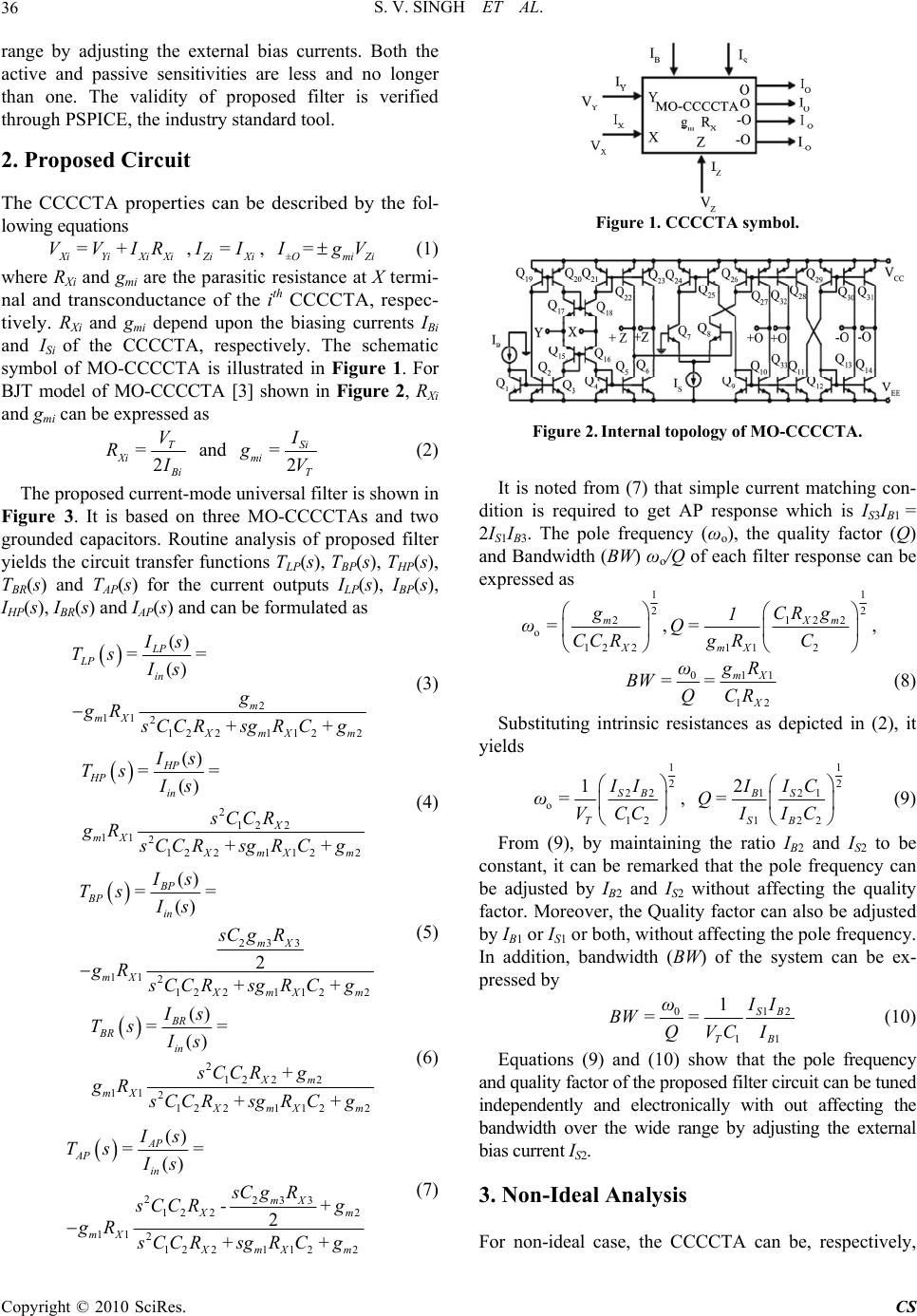 S. V. SINGH ET AL. Copyright © 2010 SciRes. CS 36 range by adjusting the external bias currents. Both the active and passive sensitivities are less and no longer than one. The validity of proposed filter is verified through PSPICE, the industry standard tool. 2. Proposed Circuit The CCCCTA properties can be described by the fol- lowing equations XiYiXi Xi V=V+IR , Z iXi I =I , = ±Omi Zi I gV (1) where RXi and gmi are the parasitic resistance at X termi- nal and transconductance of the i th CCCCTA, respec- tively. RXi and gmi depend upon the biasing currents IBi and ISi of the CCCCTA, respectively. The schematic symbol of MO-CCCCTA is illustrated in Figure 1. For BJT model of MO-CCCCTA [3] shown in Figure 2, RXi and gmi can be expressed as 2 T Xi B i V R= I and 2 Si mi T I g= V (2) The proposed current-mode universal filter is shown in Figure 3. It is based on three MO-CCCCTAs and two grounded capacitors. Routine analysis of proposed filter yields the circuit transfer functions TLP(s), TBP(s), THP(s), TBR(s) and TAP(s) for the current outputs ILP(s), IBP(s), IHP(s), IBR(s) and IAP(s) and can be formulated as 2 11 2 1221122 () () LP LP in m mX XmX m Is Ts= = Is g gR s CC R+sgRC+g (3) 2 12 2 11 2 1221122 () () HP HP in X mX XmX m Is Ts= = Is sCCR gR s CC R+sgRC+g (4) 23 3 11 2 1221122 () () 2 BP BP in mX mX XmX m Is Ts== Is sC gR gR s CC R+sgRC+g (5) 2 12 22 11 2 1221122 () () BR BR in Xm mX XmX m Is Ts== Is sCCR +g gR s CC R+sgRC+g (6) 223 3 12 22 11 2 1221122 () () 2 AP AP in mX Xm mX XmX m Is Ts= = Is sC gR s CC R-+g gR s CC R+sgRC+g (7) Figure 1. CCCCTA symbol. Figure 2. Internal topology of MO-CCCCTA. It is noted from (7) that simple current matching con- dition is required to get AP response which is IS3IB1 = 2IS1IB3. The pole frequency (ωo), the quality factor (Q) and Bandwidth (BW) ωo/Q of each filter response can be expressed as 1 2 2 o 12 2 m X g ω=CC R , 1 2 122 11 2 Xm mX CR g 1 Q= gR C , 011 12 mX X ω g R BW == QCR (8) Substituting intrinsic resistances as depicted in (2), it yields 1 2 22 o 12 1SB T II ω=VCC , 1 2 21 1 122 2S B SB IC I Q= IIC (9) From (9), by maintaining the ratio IB2 and IS2 to be constant, it can be remarked that the pole frequency can be adjusted by IB2 and IS2 without affecting the quality factor. Moreover, the Quality factor can also be adjusted by IB1 or IS1 or both, without affecting the pole frequency. In addition, bandwidth (BW) of the system can be ex- pressed by 012 11 1SB TB ω I I BW == QVCI (10) Equations (9) and (10) show that the pole frequency and quality factor of the proposed filter circuit can be tuned independently and electronically with out affecting the bandwidth over the wide range by adjusting the external bias current IS2. 3. Non-Ideal Analysis For non-ideal case, the CCCCTA can be, respectively, 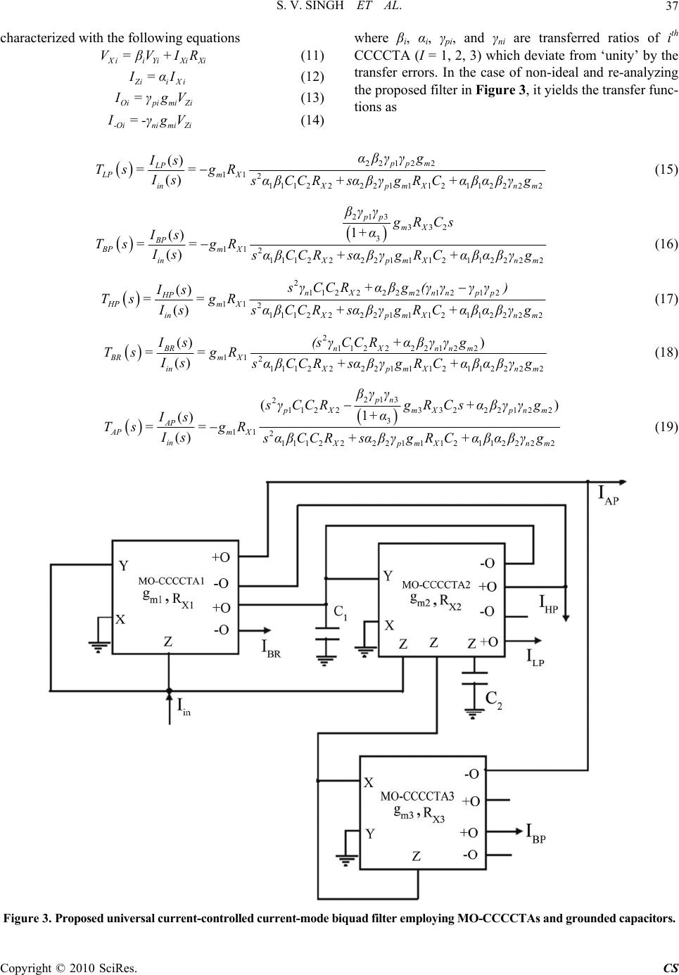 S. V. SINGH ET AL. Copyright © 2010 SciRes. CS 37 characterized with the following equations Xii YiXiXi V=βV+IR (11) Z iiXi I=α I (12) Oipimi Zi I=γ g V (13) -Oinimi Zi I=-γ g V (14) where βi, αi, γpi, and γni are transferred ratios of ith CCCCTA (I = 1, 2, 3) which deviate from ‘unity’ by the transfer errors. In the case of non-ideal and re-analyzing the proposed filter in Figure 3, it yields the transfer func- tions as 22 1 22 11 2 111 222 21112112 222 () () pp m LP LPm X in XpmXnm αβγ γg Is Ts= =gR Is sαβCC R+sαβγgRC+αβαβ γ g (15) 213 332 3 11 2 111 222 21112112 222 1 () () pp mX BP BPm X in XpmXnm βγ γgRCs +α Is Ts= =gR Is sαβCC R+sαβγ gRC+αβαβγ g (16) 2 11222221 212 11 2 111 222 2111 2112 222 () () nX mnnpp HP HPm X in XpmXnm sγCC R+αβg(γγγγ ) Is Ts= =gR Is sαβCCR+sαβγ gRC+αβαβγ g (17) 2 112222 1 22 11 2 111 222 21112112 222 ) () () nX nnm BR BRm X in XpmXnm (s γCC R+αβγ γg Is Ts= =gR Is sαβCC R+sαβγgRC+αβαβ γ g (18) 213 2 112233 222122 3 11 2 111 222 21112112 222 () 1 () () pn pXmX pnm AP APm X in XpmXnm βγγ sγCC RgRC s+αβγ γg +α Is Ts= =gR Is sαβCC R+sαβγgRC+αβαβ γ g (19) Figure 3. Proposed universal current-controlled current-mode biquad filter employing MO-CCCCTAs and grounded capacitors. 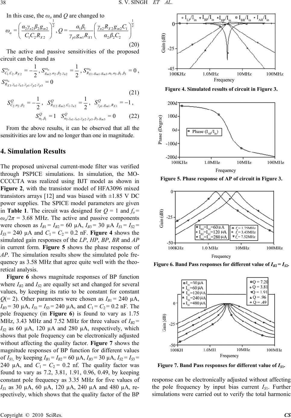 S. V. SINGH ET AL. Copyright © 2010 SciRes. CS 38 In this case, the ωo and Q are changed to 1 2 222 2 o 12 2 nm X αγ βg ω=CC R , 1 2 2221 11 11 1222 nXm pmX γRgC αβ Q= γgR αβC (20) The active and passive sensitivities of the proposed circuit can be found as 12 2 1 2 o X ω C,C ,R S=,222 2 1 2 o mn ω g,α,β,γ S=,o 1131313 0 Xmm ω R,g,g,α,α,β,β S=, 313 1230 o Xnnppp ω R,γ,γ,γ,γ,γ S= (21) 222 1 2 Q C,α,β S=, 2212 1 2 Xm n Q R,g,C,γ S= , 11 11 pm X Q γ,g ,R S= , 11 1 Q α,β S= 313233 30 nn p pm Q α,γ,γ,γ,γ,β,g S= (22) From the above results, it can be observed that all the sensitivities are low and no longer than one in magnitude. 4. Simulation Results The proposed universal current-mode filter was verified through PSPICE simulations. In simulation, the MO- CCCCTA was realized using BJT model as shown in Figure 2, with the transistor model of HFA3096 mixed transistors arrays [12] and was biased with ±1.85 V DC power supplies. The SPICE model parameters are given in Table 1. The circuit was designed for Q = 1 and fo = ωo/2π = 3.68 MHz. The active and passive components were chosen as IB1 = IB2 = 60 µA, IB3 = 30 µA IS1 = IS2 = IS3 = 240 µA and C1 = C2 = 0.2 nF. Figure 4 shows the simulated gain responses of the LP, HP, BP, BR and AP in current form. Figure 5 shows the phase response of AP. The simulation results show the simulated pole fre- quency as 3.58 MHz that agree quite well with the theo- retical analysis. Figure 6 shows magnitude responses of BP function where IB2 and IS2 are equally set and changed for several values, by keeping its ratio to be constant for constant Q(= 2). Other parameters were chosen as IB1 = 240 µA, IB3 = 30 µA, IS1 = IS3 = 240 µA, and C1 = C2 = 0.2 nF. The pole frequency (in Figure 6) is found to vary as 1.75 MHz, 3.43 MHz and 7.52 MHz for three values of IB2 = IS2 as 60 µA, 120 µA and 280 µA, respectively, which shows that pole frequency can be electronically adjusted without affecting the quality factor. Figure 7 shows the magnitude responses of BP function for different values of IS1, by keeping IB1 = IB2 = 60 µA, IB3 = 30 µA, IS2 = IS3 = 240 µA, and C1 = C2 = 0.2 nf. The quality factor was found to vary as 7.2, 3.81, 1.91, 0.96, 0.49, by keeping constant pole frequency as 3.35 MHz for five values of IS1 as 30 µA, 60 µA, 120 µA, 240 µA and 480 µA, re- spectively, which shows that the quality factor of the BP Figure 4. Simulated results of circuit in Figure 3. Figure 5. Phase response of AP of circuit in Figure 3. Figure 6. Band Pass responses for different value of IB2 = IS2. Figure 7. Band Pass responses for different value of IS1. response can be electronically adjusted without affecting the pole frequency by input bias current IS1. Further simulations were carried out to verify the total harmonic 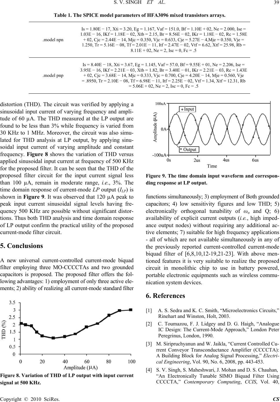 S. V. SINGH ET AL. Copyright © 2010 SciRes. CS 39 Table 1. The SPICE model parameters of HFA3096 mixed transistors arrays. .model npn Is = 1.80E − 17, Xti = 3.20, Eg = 1.167, Vaf = 151.0, Bf = 1.10E + 02, Ne = 2.000, Ise = 1.03E − 16, IKf = 1.18E − 02, Xtb = 2.15, Br = 8.56E − 02, IKr = 1.18E − 02, Rc = 1.58E + 02, Cjc = 2.44E − 14, Mjc = 0.350, Vjc = 0.633, Cje = 5.27E − 4,Mje = 0.350, Vje = 1.250, Tr = 5.16E − 08, Tf = 2.01E − 11, Itf = 2.47E − 02, Vtf = 6.62, Xtf = 25.98, Rb = 8.11E + 02, Ne = 2, Isc = 0, Fc = .5 .model pnp Is = 8.40E − 18, Xti = 3.67, Eg = 1.145, Vaf = 57.0, Bf = 9.55E + 01, Ne = 2.206, Ise = 3.95E − 16, IKf = 2.21E − 03, Xtb = 1.82, Br = 3.40E − 01, IKr = 2.21E − 03, Rc = 1.43E + 02, Cjc = 3.68E − 14, Mjc = 0.333, Vjc = 0.700, Cje = 4.20E − 14, Mje = 0.560, Vje = .8950, Tr = 2.10E − 08, Tf = 6.98E − 11, Itf = 2.25E − 02, Vtf = 1.34, Xtf = 12.31, Rb = 5.06E + 02, Ne = 2, Isc = 0, Fc = .5 distortion (THD). The circuit was verified by applying a sinusoidal input current of varying frequency and ampli- tude of 60 µA. The THD measured at the LP output are found to be less than 3% while frequency is varied from 30 KHz to 1 MHz. Moreover, the circuit was also simu- lated for THD analysis at LP output, by applying sinu- soidal input current of varying amplitude and constant frequency. Figure 8 shows the variation of THD versus applied sinusoidal input current at frequency of 500 KHz for the proposed filter. It can be seen that the THD of the proposed filter circuit for the input current signal less than 100 µA, remain in moderate range, i.e ., 3%. The time domain response of current-mode LP output (ILP) is shown in Figure 9. It was observed that 120 µA peak to peak input current sinusoidal signal levels having fre- quency 500 KHz are possible without significant distor- tions. Thus both THD analysis and time domain response of LP output confirm the practical utility of the proposed current-mode filter circuit. 5. Conclusions A new universal current-controlled current-mode biquad filter employing three MO-CCCCTAs and two grounded capacitors is proposed. The proposed filter offers the fol- lowing advantages: 1) employment of only three active ele- ments; 2) ability of realizing all current-mode standard filter Figure 8. Variation of THD of LP output with input current signal at 500 KHz. Figure 9. The time domain input waveform and correspon- ding response at LP output. functions simultaneously; 3) employment of Both grounded capacitors; 4) low sensitivity figures and low THD; 5) electronically orthogonal tunability of ωo and Q; 6) availability of explicit current outputs (i.e., high imped- ance output nodes) without requiring any additional ac- tive elements; 7) suitable for high frequency applications - all of which are not available simultaneously in any of the previously reported current-controlled current-mode biquad filter of [6,8,10,12-19,21-23]. With above men- tioned features it is very suitable to realize the proposed circuit in monolithic chip to use in battery powered, portable electronic equipments such as wireless commu- nication system devices. 6. References [1] A. S. Sedra and K. C. Smith, “Microelectronics Circuits,” Rinehart and Winston, Holt, 2003. [2] C. Toumazou, F. J. Lidgey and D. G. Haigh, “Analogue IC Design: The Current-Mode Approach,” London Peter Peregrinus, London, 1990. [3] M. Siripruchyanun and W. Jaikla, “Current Controlled Cu- rrent Conveyor Transconductance Amplifier (CCCCTA): A Building Block for Analog Signal Processing,” Electri- cal Engineering, Vol. 90, No. 6, 2008, pp. 443-453. [4] S. V. Singh, S. Maheshwari, J. Mohan and D. S. Chauhan, “An Electronically Tunable SIMO Biquad Filter Using CCCCTA,” Contemporary Computing, CCIS, Vol. 40,  S. V. SINGH ET AL. Copyright © 2010 SciRes. CS 40 2009, pp. 544-555. [5] A. M. Soliman, “New Current-Mode Filters Using Current Conveyors,” International Journal of Electronics and Communications (AEÜ), Vol. 51, No. 3, 1997, pp. 275- 278. [6] S. Minaei and S. Türköz, “New Current-Mode Current- Controlled Universal Filter with Single Input and Three Outputs,” International Journal of Electronics, Vol. 88, No. 3, 2001, pp. 333-337. [7] R. Senani, “New Current Mode Biquad Filter,” Interna- tional Journal of Electronics, Vol. 73, No. 4, 1992, pp. 735-742. [8] A. U. Keskin, D. Biolek, E. Hancioglu and V. Biolkova, “Current-Mode KHN Filter Employing Current Differ- encing Transconductance Amplifiers,” International Journal of Electronics and Communications (AEÜ), Vol. 60, No. 6, 2006, pp. 443-446. [9] M. Soliman, “Current Mode Universal Filters with Grou- nded Passive Elements and Using Single Output Current Conveyors,” Journal of Active and Passive Electronics Devices, Vol. 4, 2009, pp. 55-62. [10] S. Maheshwari and I. A. Khan, “Novel Cascadable Cur- rent-Mode Translinear-C Universal Filter,” Active Pas- sive Electronics Components, Vol. 27, No. 4, 2004, pp. 215-218. [11] C. Wang, Y. Zhao, Q. Zhang and S. Du, “A New Current Mode SIMO-Type Universal Biquad Employing Multi- Output Current Conveyors (MOCCIIs),” Radioengineer- ing, Vol. 18, No. 1, 2009, pp. 83-88. [12] R. Senani, V. K. Singh, A. K. Singh and D. R. Bhaskar, “Novel Electronically Controllable Current-Mode Uni- versal Biquad Filter,” The Institute of Electronics, Infor- mation and Communication Engineers, Vol. 1, No. 14, 2004, pp. 410-415. [13] W. Kiranon, J. Kesorn and N. Kamprasert, “Electroni- cally Tunable Multi-Function Translinear-C Filter and Oscillators,” Electronics Letters, Vol. 33, No. 7, 1997, pp. 573-574. [14] S. Maheshwari and I. A. Khan, “High Performance Ver- satile Translinear-C Universal Filter,” Journal of Active and Passive Electronics Devices, Vol. 1, No. 2, 2005, pp. 41-51. [15] M. T. Abuelma’atti and N. A. Tassaduq, “New Current- Mode Current Controlled Filters Using Current-Controll- ed Conveyor,” International Journal of Electronics, Vol. 85, No. 4, 1998, pp. 483-488. [16] T. Katoh, T. Tsukutani, Y. Sumi and Y. Fukui, “Electro- nically Tunable Current-Mode Universal Filter Employ- ing CCCIIs and Grounded Capacitors,” International Symposium on Intelligent Signal Processing and Com- munications Systems, 2006, pp. 107-110. [17] C. Wang, H. Liu and Y. Zhao, “A New Current-Mode Current-Controlled Universal Filter Based on CCCII (±),” Circuits System Signal Processing, Vol. 27, No. 5, 2008, pp. 673-682. [18] S. Minaei and S. Türköz, “Current-Mode Electronically Tunable Universal Filter Using Only Plus-Type Current Controlled Conveyors and Grounded Capacitors,” Elec- tronics and Telecommunications Research Institute Jour- nal, Vol. 26, No. 4, 2004, pp. 292-296. [19] M. T. Abuelma’atti and N. A. Tassaduq, “A Novel Sin- gle-Input Multiple-Output Current-Controlled Universal Filter,” Microelectronics Journal, Vol. 29, No. 11, 1998, pp. 901-905. [20] S. Maheshwari, “Current-Mode Filters with High Output Impedance and Employing only Grounded Components,” WSEAS Transactions on Electronics, Vol. 5, No. 1, 2008, pp. 238-243. [21] W. Jaikla and M. Siripruchyanun, “A Cascadable Cur- rent-Mode Universal Biquadratic Filter Using MO- CCCCTAs,” IEEE Conference, Pisa, 2008, pp. 952-955. [22] D. Biolek and V. Biolkova, “CDTA-C Current-Mode Universal 2nd Order Filter,” Proceeding of the 5th Inter- national Conference on Applied Informatics and Com- munications, Malta, 2003, pp. 411-414. [23] W. Tangsrirat and W. Surakampontorn, “Systematic of Cascadable Current-Mode Filters Using CDTAs,” Fre- quenz, Vol. 60, No. 11-12, 2006, pp. 241-245. |