International Journal of Medical Physics, Clinical Engineering and Radiation Oncology, 2013, 2, 1-5
Published Online February 2013 (http://www.scirp.org/journal/ijmpcero)
http://dx.doi.org/10.4236/ijmpcero.2013.21001
Copyright © 2013 SciRes. IJMPCERO
Effects of Beam Startup Characteristics on Dose Delivery
Accuracy at Low Monitor Units in Step-and-Shoot
Intensity Modulated Radiation Therapy
Kazunori Fujimoto1,2, Kunihiko Tateoka1,3, Yuji Yaegashi1, Katsumi Shima1, Junji Suzuki1,
Yuichi Saito1, Akihiro Nakata1, Takuya Nakazawa1, Tadanori Abe1, Masaki Yano1,
Masanori Someya3, Kensei Nakata3, Mas aka zu Hori3, Masato Hareyama2, Koichi Sakata1,3
1Department of Medical Physics, Graduate School of Medicine, Sapporo Medical University, Sapporo, Japan
2Radiation Therapy Research Institute, Social Medical Corporation Teishinkai, Sapporo, Japan
3Department of Radiology, Sapporo Medical University, Sapporo, Japan
Email: tateoka@sapmed.ac.jp
Received September 11, 2012; revised October 15, 2012; accepted October 23, 2012
ABSTRACT
Intensity modulated radiation therapy (IMRT) is a highly accurate technique that is usually implemented in either dy-
namic or step-and-shoot fashion with many segments each having low monitor units (MUs). The present study evalu-
ated the effects of beam startup characteristics on the dose delivery accuracy for each segment at low MUs for
step-and-shoot IMRT with an Elekta Precise accelerator at the highest dose rates. We used a two-dimensional semi-
conductor detector for the dose measurements. The field size of each segment was assumed to be 20 × 20 cm2 and each
segment was set to deliver 1 - 10 MUs. Our results show a variation in dose delivery accuracy between segments for the
same IMRT beam, which can be attributed to the beam startup characteristics. This variability is attributed to the
changes in the transient changes in the temperatures of the electron gun filament and the magnetron. That is, the tran-
sient increase in the temperature of the filament leads to increasing doses with time and that of the magnetron leads to
decreasing doses with time during the first few MUs.
Keywords: Startup Performance; Step-and-Shoot IMRT; Low Monitor Units
1. Introduction
The goal of radiotherapy is to achieve tumor control by
delivering a prescribed dose to a defined target volume,
and to minimize delivered dose to neighboring normal
tissue. Intensity modulated radiation therapy (IMRT) [1,2]
is one popular method of achieving accurate dose deliv-
ery. IMRT is usually implemented using a multi-leaf col-
limator (MLC) in either the step-and-shoot or dynamic
modes. In the latter mode, the intensity modulated beam
forms irregularly shaped fields made by moving the MLC
continuously during irradiation. In the former, multiple,
small, irregularly shaped fields are created with the MLC
(segments) and each can deliver an arbitrary number of
monitor units (MUs), including low MUs (<10 MU). In
both modes, it is necessary to deliver the correct dose for
irregularly shaped fields made in the MLC. However,
studies conducted on the beam characteristics at low
MUs in IMRT have generally shown that the dose is
nonlinear, nonuniform, and not reproducible at low MUs
[3-7]. In particular, at low dose rates, the total beam-on
time between the beam-on of the first segment and the
beam-off of the last segment during IMRT becomes long-
er than planned, leading to a somewhat low average dose
rate. This has been found to affect the survival ratio of
human cancer cells at different dose rates [8]. Moreover,
a lower-than-planned dose rate leaves greater risk for
repopulation of tumor cells as compared with acute irra-
diation, which favors the use of shorter irradiation times
in IMRT by reducing the number of beams and segments
through optimization of the number of subfields [9,10].
For step-and-shoot IMRT, therefore, it is important to
adopt the highest possible dose rate that the linear accel-
erator can deliver.
Ezzell and Chungbin [3] reported that more MUs are
delivered than planned with a radiation treatment plan-
ning system (RTPs) in the first segment of the IMRT
beam when using a Varian accelerator; this is called the
overshoot phenomenon. Likewise, Kang et al. [4] show-
ed dose differences of up to 4% - 5% can occur when
using irradiation at less than 7 MU. These differences
stem from the electronic delay in the control loop for the
MLC and beam controller system, which are controlled
by separate CPUs. Similarly, several reports have shown
increased dose differences at low MUs in a segment of a
K. FUJIMOTO ET AL.
2
step-and-shoot IMRT beam from accelerators manufac-
tured by Philips, Siemens, and Elekta [5-7]. They showed
that the cause of this dose difference was variation in the
gun current or microwaves from the magnetron/klystron
(high-power linear accelerators) during beam control
(on/off) for segments in step-and-shoot IMRT. As a re-
sult, they were recommended use low dose rates as a so-
lution to this problem.
In addition, for the Varian and Siemens linear accel-
erators, beam control is initiated by the grid pulse of the
triode gun at high power settings. However, for the
Elekta and Philips accelerators, only the first segment is
initiated with pulses form the diode gun and microwaves
from the magnetron at high power; from the second seg-
ment onward, the beam is initiated by the microwaves
from the magnetron only. Moreover, some studies have
shown a correlation between the arbitrary dose rate and
the average dose delivered over three or five segments
with the same low MU in step-and shoot IMRT. Finally,
the beam startup characteristics could also affect dose at
low MUs because of differences in beam control meth-
ods [11]. However, there have been no reported studies
on the effects of beam startup characteristics on the dose
delivery accuracy in each segment in step-and-shoot
IMRT.
In this study, the effects of beam startup characteristics
on the dose delivery accuracy for each segment at low
MUs was investigated for step-and-shoot IMRT at the
highest dose rate on an Elekta Precise accelerator (Pre-
cise Desktop 4.1, Elekta Ltd Crawley UK), the machine
available at the author’s institution.
2. Materials and Methods
Step-and-shoot IMRT beams having five segments were
made by irradiating a virtual water equivalent phantom
(30 × 30 × 12.3 cm3) using a treatment planning system
(Pinnacle3, Philips Radiation Oncology System, Madison,
WI). The treatment plan data acquired from Pinnacle3
were imported to the Elekta Precise accelerator. The field
size of each segment was set to 20 × 20 cm2 with a
source-to-surface distance (SSD) of 95 cm (i.e., source-
to-target distance of 100 cm). Then, each segment was
delivered perpendicularly to a 2D diode array detector
(MapCheck, Sun Nuclear Corporation, Melbourne, USA)
connected to a control computer. The MapCheck detector
was placed between square water equivalent phantoms
(Tough Water, Kyoto Kagaku Co., Ltd, Kyoto, Japan)
with the dimensions 30 × 30 × 3 cm3 and 30 × 30 × 5
cm3, the SSD was 95 cm (i.e., source-to-detector distance
(SDD) of 100 cm). The measurement depth was 5 cm
water equivalent depth. This combination of water
equivalent phantom and Mapcheck was similar to the
treatment plan data from Pinnacle3. Dose calibration for
the MapCheck detector was performed on an Elekta Pre-
cise accelerator with 10-MV photons, a field size of 20 ×
20 cm2, dose of 200 MU, SDD of 100 cm, and measure-
ment depth of 5 cm water.
All the measurements were performed for one fixed
MU in each of the five segments, where the dosage was
increased from 1 to 10 MUs in steps of 1 MU and then
set to 200 MU. For each MU setting, five repeated mea-
surements were acquired in a random sequence. There-
fore, each segment was measured at each MU a total of
five times and the total number of segments that deliv-
ered the same MU was 25. However, before the meas-
urements, 500 MUs were dosed to avoid a systematic
influence from the beam history (e.g., by warming of the
electron gun). The measurements were performed with
10-MV photons at the maximum dose rate (480 MU/min)
of the Elekta Precise accelerator.
Note that the dose of the Elekta Precise accelerator is
checked daily with a square field (10 × 10 cm2), which
delivers about 2 Gy (corresponding to 200 MU), which is
similar to the dose calibration method of all medical ac-
celerators. Thus, the dose calibration factor of the moni-
tor chamber of an Elekta Precise accelerator was used to
deliver the correct dose.
In this report, the percent difference (r) between the
dose delivered in each segment (xMU) and a dose of 200
MUs with a conventional radiation beam was determined
for each measurement as follows:


DMU 200
%1 100
D200MU
x
rx




(1)
where D(xMU) and D(200 MU) are the Mapcheck read-
ings for xMU and 200 MU. A value of r = 0% is ex-
pected for a perfect dose. By using this equation, one can
clearly see the percent difference of another MU.
3. Results
For comparison with previous results [3-7], we plotted
the percent differences as a function of segment MU de-
livered for step-and-shoot IMRT with five identical seg-
ments and 10-MV X-ray photons at a dose rate of 480
MU/min using the Elekta Precise accelerator (Figure 1).
The tolerance of the X-ray monitor unit linearity of an
IMRT has been reported to be ±2% (5 MUs) and ±5%
(2 - 4 MUs) in the AAPM TG-142 [12].The average dif-
ference was 7.5% and the standard deviation was about
±4% when 1 MU was delivered per segment. However,
the average was within about 4% and 2% of the ex-
pected value when more than 2 MUs and 7 MUs were
delivered per segment, respectively. Moreover, a de-
creasing trend can be seen in the average percent differ-
ence as the dose per segment increases. Note that all the
differences were negative and the standard deviation was
about ±0.8% at 2 - 6 MUs per segment. Further, the av-
Copyright © 2013 SciRes. IJMPCERO
K. FUJIMOTO ET AL. 3
Figure 1. Percent difference (r) between the average dose
delivered at various segment MUs and a 200 MU delivery.
Symbols and error bars represent the averages and stan-
dard deviations of a total of 25 measurements.
erage percent difference and standard deviation were
highest at 1 MU. These findings are consistent with those
of previous publications [3-7].
Next, to analyze the effects of beam startup character-
istic on dose accuracy at low MUs, we plotted the per-
cent difference in each segment as a function of the dose,
as shown in Figure 2. At 1 MU per segment, the average
percent difference was about 1% in the first segment,
but between 7% and 13% for the rest; that is, the first
segment and other segments showed different trends. In
addition, the percent difference in the first segment was
within 3% for all of doses, but decreased with an in-
crease in the dose for the other segments, which is in
close agreement with the results in Figure 1. The stan-
dard deviation is within about ±5% for all of segments at
1 MU per segment, but reduces to about ±1.2% from 2
MU per segment. Thus, the first segment differs from the
other segments possibly because of beam startup charac-
teristics at low MUs in step-and-shoot IMRT. Further-
more, the percent differences in the second to the fifth
segment were in close agreement for all doses.
To investigate the first segment further, the percent
average difference of the first segment was compared
against that of the other segments taken together as a
function of segment MU (Figure 3). The discrepancy
between the first and subsequent segments was the larg-
est at 1 MU, but decreased to 3% at 2 - 6 MUs and then
to 1% at 7 MUs.
4. Discussion
Our results show that the percent average differences and
standard deviations for all segments (a total of 25 measu-
rements) were largest at 1 MU per segment MU (Figure
1). This is consistent with previous reports on the Varian
21EX and Siemens PRIMUS accelerators [3,4,12]. For
the former, Kang et al. [4] showed that the dose differ-
ence at low MUs could be attributed to the communica-
Figure 2. Percent difference (r) between the average deli-
vered dose at various segments MUs in each segment and a
200 MU delivery. Symbols and error bars represent the
averages and standard deviations of a total of 5 measure-
ments.
Figure 3. Percent difference (r) between the average dose
delivered at various segment MUs for the first segment and
the second to the fifth segment relative to a 200 MU delivery.
Symbols and error bars represent the averages and stan-
dard deviations of a total of five measurements (for the first
segment) and 20 measurements for second to the fifth seg-
ment.
tion delay between the separate beam controller and MLC
controllers; the communication time is 50 ms for Varian
linear accelerators [3]. For the latter, Saw et al. [12] re-
ported similar behavior at less than 5 MU. They could be
attributed to the time constant of the integration circuit of
the monitor chamber, which is component-specific and
regardless of the prescribe dose (planned MUs). This is
because the integrated current from the monitor ioniza-
tion chamber of the accelerator is used as a beam-off
trigger. Similarly, the Elekta accelerator also has a sig-
nificant time constant (40 ms) for the integration circuit
of the monitor chamber, which could explain larger dif-
ferences and standard deviations at 1 MU per segment.
However, the influence of the beam control technique on
the dose delivered in each segment has not been previ-
ously investigated.
Next, as shown in Figures 2 and 3, we found that the
Copyright © 2013 SciRes. IJMPCERO
K. FUJIMOTO ET AL.
4
percent difference can be expected to be within 3% for
all segment MUs in the first segment. However, it is
nearly the same from the second to the fifth segment and
shows a decrease with an increase in segment MU deli-
vered. This result has not been previously reported. Mohr
et al. [7] and Hansen et al. [13] indicated that beam qua-
lity may vary with time, especially during the first few
MUs, which translates into variations in the beam quality
factor q and the depth-dose curve. However, they did not
per- form a detailed analysis into why the beam energy
varies with time during the first few MUs.
Here we consider two possible factors: the diode gun
and the magnetron in high-power accelerators such as the
Elekta Precise accelerator [14]. First, the X-ray beam of
the Elekta Precise accelerator is turned on or off when a
pulse voltage from the high-power linear accelerators is
applied to the magnetron. However, this can cause rapid
heating of the magnetron by eddy currents, which can
affect its resonance structure. As a result, the resonant
frequency of the magnetron decreases, as does the fre-
quency of output microwaves. Therefore, the accelera-
tion efficiency of electrons from the electron gun is de-
creased and the beam energy of the linear accelerator
could show a slight reduction. The magnetron does in-
clude a metal tuner that must move into position to cor-
rect for these variations. However, it takes approximately
200 ms from the time the X-ray beam is turned on for the
electron acceleration efficiency to recover to normal
values.
Second, the filament of the electron gun is heated im-
mediately after the beam is turned on. The temperature of
the filament is slightly low just after the beam is turned
on, which could result in somewhat fewer electrons
(smalller beam current). As a result, the beam energy of
the linear accelerator could slightly increase.
These two factors could explain the time variation,
especially during the first few MUs and the change in the
depth-dose curve, as described by Mohr et al. [7] and
Hansen et al. [13]. The beam for the first segment is ini-
tiated by a pulse from the diode gun and the microwaves
from the magnetron (high-power accelerators), but from
the second segment onward, the beam is switched on and
off based on the microwaves from the magnetron.
In this study, the time required to deliver 1 MU was
125 ms, which can be calculated from the dose rate of
480 MU/min and pulse rate frequency (PRF) of 400 Hz
for the Elekta Precise accelerator. Therefore, when set to
deliver 1 MU per segment (125 ms), the beam energy in
the first segment could increase slightly with time due to
the influence the electron gun filament and could be de-
crease slightly with time due to the influence of the
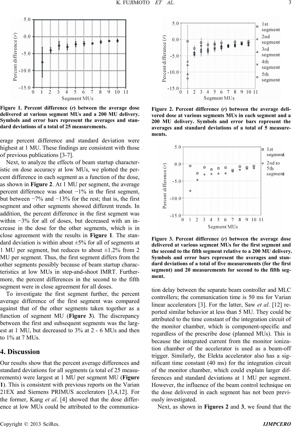
magnetron during the first few MUs. This could explain
the small percent difference at 1 MU per segment, as
shown in Figure 3. In contrast, the beam energy in the
second and subsequent segments at 1 MU per segment
(125 ms) could decrease slightly with time due to the
influence of the magnetron during the first few MUs.
This explains the larger differences seen in Figure 3 at 1
MU per segment.
Next, at 2 MUs per segments (240 ms), there may be
sufficient time for the influences the filament and mag-
netron temperatures to reduce gradually (over several and
several hundred milliseconds, respectively). This ex-
plains the small differences seen in Figure 3 for the first
segment at 2 MUs per segment. Then, in the second and
subsequent segments, the influence the magnetron tem-
perature can also reduce gradually over several hundred
milliseconds, which explains the reduced differences in
the second and subsequent segments at 2 MUs per seg-
ment.
Regarding the fact that the impact of the beam start-up
control is different for subsequent segments from the first
segment of the step-and-shoot IMRT beam in the Elekta-
linac, which is focused in this study, from a com-parison
of the dose of a low MU with the dose of the overall
IMRT plan, the effect of the treatment plan is considered
small.
In addition, the temperatures of the filament and mag-
netron are related to the flatness, symmetry, and homo-
geneity of IMRT beam. This represents is a far more
complicated problem and needs further study. Further
work is underway to clarify these relationships.
In conclusion, the study showed that the transient
temperatures of the electron gun filament and magnetron,
which determine to the beam startup characteristics, also
affect the dose in each segment at low MUs in step-and-
shoot IMRT with the Elekta Precise accelerator. That is,
the temperature change of the electron gun filament can
increase the dose with time and that of the magnetron can
decrease the dose with time during the first few MUs.
5. Acknowledgments
The authors are grateful to Dr. Jun Takada and Dr. Ken-
ichi Tanaka of Department of Physics, Graduate school
of Medicine, Sapporo Medical University for their exten-
sive physics support. We appreciate the advice from the
beginning to the end of this study from Dr. Kiyoshi Yoda
of the medical physics division at ELEKTA Corporation.
We also thank Dr. MiyakoMyoujin, a radiation oncolo-
gist at Keiyukai Sapporo Hospital, who understood the
purpose of this study and cooperated willingly. In addi-
tion, we thank all the radiological technologists at Kei-
yukai Sapporo Hospital.
REFERENCES
[1] V. Y. Kuperman and W.-C. Lam, “Improving Delivery of
Segments with Small MU in Step-and-Shoot IMRT,” Me-
dical Physics, Vol. 33, No. 4, 2006, pp. 1067-1073.
Copyright © 2013 SciRes. IJMPCERO
K. FUJIMOTO ET AL.
Copyright © 2013 SciRes. IJMPCERO
5
doi:10.1118/1.2174128
[2] R. D. Wiersma and L. Xing “Examination of Geometric
Accuracies of Gated Step-and-Shoot Intensity Modulated
Radiation Therapy,” Medical Physics, Vol. 34, No. 10,
2007, pp. 3962-3970. doi:10.1118/1.2776671
[3] G. A. Ezzell and S. Chungbin, “The Overshoot Phenome-
non in Step-and-Shoot IMRT Delivery,” Journal of Ap-
plied Clinical Medical Physics, Vol. 2, No. 3, 2001, pp.
138-148. doi:10.1120/1.1386508
[4] S.-K. Kang, K.-H. Cheong, T. Hwang, B. C. Cho, S. S.
Kim, K. J. Kim, D. H. Oh and H. Bae, “Dosimetric Cha-
racteristics of Linear Accelerator Photon Beams with
Small Monitor Unit Setting,” Medical Physics, Vol. 35,
No. 11, 2008, pp. 5172-5178. doi:10.1118/1.2995759
[5] V. N. Hansen, P. M. Evans, G. J. Budgell, J. H. L. Mott, P.
C. Williams, M. J. P. Brugmans, F. W. Wittkämper, B. J.
Mijnheer and K. Brown, “Quality Assurance of the Dose
Delivery by Small Radiation Segments,” Physics in Me-
dicine an d Biology, Vol. 43, No. 9, 1998, pp. 2665-2675.
doi:10.1088/0031-9155/43/9/017
[6] M. Ravikumar, M. A. Al Asmary, R. A. Sultan and H. A.
Al Ghamdi, “Dose Delivery Accuracy of Therapeutic
Photon and Electron Beams at Low Monitor Unit Set-
ting,” Strahlentherapie und Onkologie, Vol. 181, No. 12,
2005, pp. 796-799. doi:10.1007/s00066-005-1412-9
[7] P. Mohr, S. Brieger, J. Stahl and G. Witucki, “Linearity
of the Dose Monitor System at Low Monitor Units,” Stra-
hlentherapie und Onkologie, Vol. 183, No. 6, 2007, pp.
327-331. doi:10.1007/s00066-007-1596-2
[8] V. Moiseenko, C. Duzenli and R. E. Durand, “In Vitro
Study of Cell Survival Following Dynamic MLC Inten-
sity-Modulated Radiation Therapy Dose Delivery,” Medi-
cal Physics, Vol. 34, No. 4, 2007, pp. 1514-1520.
doi:10.1118/1.2712044
[9] J. Z. Wang, X. A. Li, W. D. D’Souza and R. D. Stewart,
“Impact of Prolonged Fraction Delivery Times on Tumor
Control: A Note of Caution for Intensity-Modulated Ra-
diation Therapy (IMRT),” International Journal of Ra-
diation Oncology, Biology, Physics, Vol. 57, No. 2, 2003,
pp. 543-552. doi:10.1016/S0360-3016(03)00499-1
[10] H. Paganetti, “Changes in Tumor Cell Response Due to
Prolonged Dose Delivery Times in Fractionated Radia-
tion Therapy,” International Journal of Radiation On-
cology, Biology, Physics, Vol. 63, No. 3, 2005, pp. 892-
900. doi:10.1016/j.ijrobp.2005.07.953
[11] M. Buchgeister and F. Nüsslin, “Startup Performance of
the Traveling Wave versus Standing Wave Linear Acce-
lerator,” Medical Physics, Vol. 25, No. 4, 1998, pp. 493-
495. doi:10.1118/1.598225
[12] E. E. Klein, et al., “Task Group 142 Report: Quality As-
surance of Medical Accelerator,” Medical Physics, Vol.
36, No. 9, 2009, pp. 4197-4212. doi:10.1118/1.3190392
[13] C. B. Saw, S. Li, K. M. Ayyangar, M. Yoe-Sein, S. Pillai,
C. A. Enke and J. C. Celi, “Dose Linearity and Uniformi-
ty of a Linear Accelerator Designed for Implementation
of Multileaf Collimation System-Based Intensity Modu-
lated Radiation Therapy,” Medical Physics, Vol. 30, No.
8, 2003, pp. 2253-2256. doi:10.1118/1.1592640
[14] D. Greene and P. C. Williams, “Linear Accelerators for
Radiation Therapy,” 2nd Edition, Taylor & Francis, New
York, 1997.