Paper Menu >>
Journal Menu >>
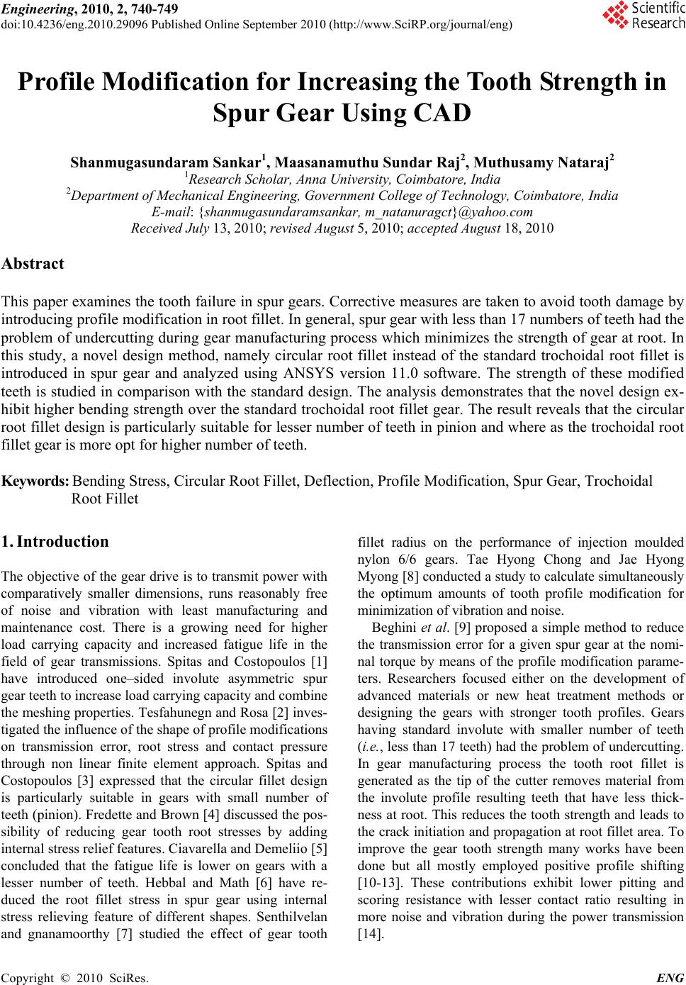 Engineering, 2010, 2, 740-749 doi:10.4236/eng.2010.29096 Published Online September 2010 (http://www.SciRP.org/journal/eng) Copyright © 2010 SciRes. ENG Profile Modification for Increasing the Tooth Strength in Spur Gear Using CAD Shanmugasundaram Sankar1, Maasanamuthu Sundar Raj2, Muthusamy Nataraj2 1Research Scholar, Anna University, Coimbatore, India 2Department of Mechanical Engineering, Government College of Technology, Coimbatore, India E-mail: {shanmugasundaramsankar, m_natanuragct}@yahoo.com Received July 13, 2010; revised August 5, 2010; accepted August 18, 2010 Abstract This paper examines the tooth failure in spur gears. Corrective measures are taken to avoid tooth damage by introducing profile modification in root fillet. In general, spur gear with less than 17 numbers of teeth had the problem of undercutting during gear manufacturing process which minimizes the strength of gear at root. In this study, a novel design method, namely circular root fillet instead of the standard trochoidal root fillet is introduced in spur gear and analyzed using ANSYS version 11.0 software. The strength of these modified teeth is studied in comparison with the standard design. The analysis demonstrates that the novel design ex- hibit higher bending strength over the standard trochoidal root fillet gear. The result reveals that the circular root fillet design is particularly suitable for lesser number of teeth in pinion and where as the trochoidal root fillet gear is more opt for higher number of teeth. Keywords: Bending Stress, Circular Root Fillet, Deflection, Profile Modification, Spur Gear, Trochoidal Root Fillet 1. Introduction The objective of the gear drive is to transmit power with comparatively smaller dimensions, runs reasonably free of noise and vibration with least manufacturing and maintenance cost. There is a growing need for higher load carrying capacity and increased fatigue life in the field of gear transmissions. Spitas and Costopoulos [1] have introduced one–sided involute asymmetric spur gear teeth to increase load carrying capacity and combine the meshing properties. Tesfahunegn and Rosa [2] inves- tigated the influence of the shape of profile modifications on transmission error, root stress and contact pressure through non linear finite element approach. Spitas and Costopoulos [3] expressed that the circular fillet design is particularly suitable in gears with small number of teeth (pinion). Fredette and Brown [4] discussed the pos- sibility of reducing gear tooth root stresses by adding internal stress relief features. Ciavarella and Demeliio [5] concluded that the fatigue life is lower on gears with a lesser number of teeth. Hebbal and Math [6] have re- duced the root fillet stress in spur gear using internal stress relieving feature of different shapes. Senthilvelan and gnanamoorthy [7] studied the effect of gear tooth fillet radius on the performance of injection moulded nylon 6/6 gears. Tae Hyong Chong and Jae Hyong Myong [8] conducted a study to calculate simultaneously the optimum amounts of tooth profile modification for minimization of vibration and noise. Beghini et al. [9] proposed a simple method to reduce the transmission error for a given spur gear at the nomi- nal torque by means of the profile modification parame- ters. Researchers focused either on the development of advanced materials or new heat treatment methods or designing the gears with stronger tooth profiles. Gears having standard involute with smaller number of teeth (i.e., less than 17 teeth) had the problem of undercutting. In gear manufacturing process the tooth root fillet is generated as the tip of the cutter removes material from the involute profile resulting teeth that have less thick- ness at root. This reduces the tooth strength and leads to the crack initiation and propagation at root fillet area. To improve the gear tooth strength many works have been done but all mostly employed positive profile shifting [10-13]. These contributions exhibit lower pitting and scoring resistance with lesser contact ratio resulting in more noise and vibration during the power transmission [14]. 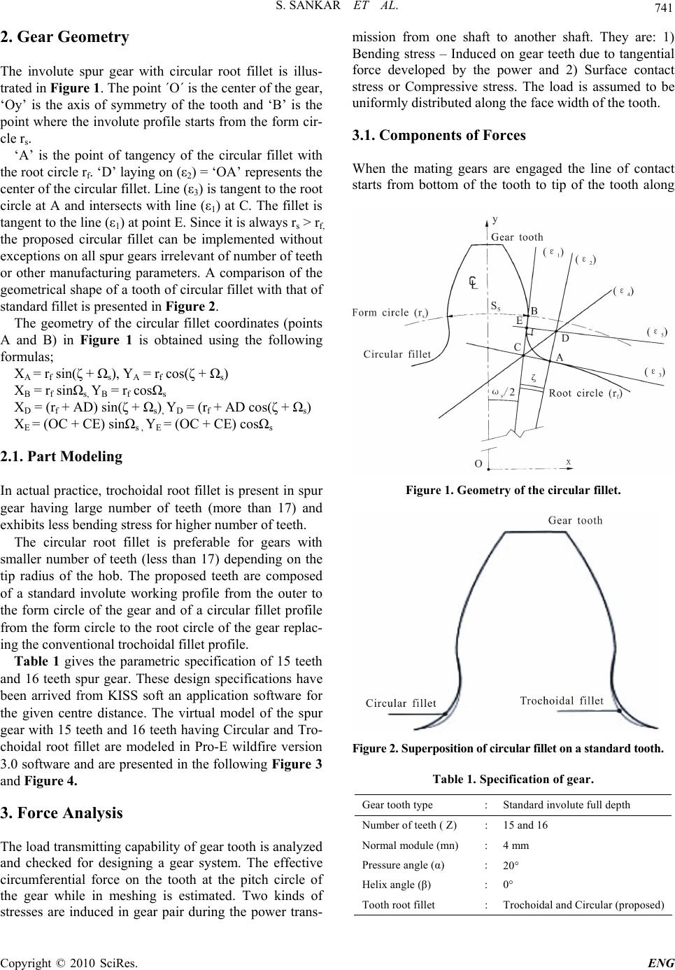 S. SANKAR ET AL. Copyright © 2010 SciRes. ENG 741 2. Gear Geometry The involute spur gear with circular root fillet is illus- trated in Figure 1. The point ´O´ is the center of the gear, ‘Oy’ is the axis of symmetry of the tooth and ‘B’ is the point where the involute profile starts from the form cir- cle rs. ‘A’ is the point of tangency of the circular fillet with the root circle rf. ‘D’ laying on (ε2) = ‘OA’ represents the center of the circular fillet. Line (ε3) is tangent to the root circle at A and intersects with line (ε1) at C. The fillet is tangent to the line (ε1) at point E. Since it is always rs > rf, the proposed circular fillet can be implemented without exceptions on all spur gears irrelevant of number of teeth or other manufacturing parameters. A comparison of the geometrical shape of a tooth of circular fillet with that of standard fillet is presented in Figure 2. The geometry of the circular fillet coordinates (points A and B) in Figure 1 is obtained using the following formulas; XA = rf sin(ζ + Ωs), YA = rf cos(ζ + Ωs) XB = rf sinΩs, YB = rf cosΩs XD = (rf + AD) sin(ζ + Ωs), YD = (rf + AD cos(ζ + Ωs) XE = (OC + CE) sinΩs , YE = (OC + CE) cosΩs 2.1. Part Modeling In actual practice, trochoidal root fillet is present in spur gear having large number of teeth (more than 17) and exhibits less bending stress for higher number of teeth. The circular root fillet is preferable for gears with smaller number of teeth (less than 17) depending on the tip radius of the hob. The proposed teeth are composed of a standard involute working profile from the outer to the form circle of the gear and of a circular fillet profile from the form circle to the root circle of the gear replac- ing the conventional trochoidal fillet profile. Table 1 gives the parametric specification of 15 teeth and 16 teeth spur gear. These design specifications have been arrived from KISS soft an application software for the given centre distance. The virtual model of the spur gear with 15 teeth and 16 teeth having Circular and Tro- choidal root fillet are modeled in Pro-E wildfire version 3.0 software and are presented in the following Figure 3 and Figure 4. 3. Force Analysis The load transmitting capability of gear tooth is analyzed and checked for designing a gear system. The effective circumferential force on the tooth at the pitch circle of the gear while in meshing is estimated. Two kinds of stresses are induced in gear pair during the power trans- mission from one shaft to another shaft. They are: 1) Bending stress – Induced on gear teeth due to tangential force developed by the power and 2) Surface contact stress or Compressive stress. The load is assumed to be uniformly distributed along the face width of the tooth. 3.1. Components of Forces When the mating gears are engaged the line of contact starts from bottom of the tooth to tip of the tooth along Figure 1. Geometry of the circular fillet. Figure 2. Superposition of circular fillet on a standard tooth. Table 1. Specification of gear. Gear tooth type :Standard involute full depth Number of teeth ( Z) :15 and 16 Normal module (mn) :4 mm Pressure angle (α) :20 Helix angle (β) :0° Tooth root fillet :Trochoidal and Circular (proposed) 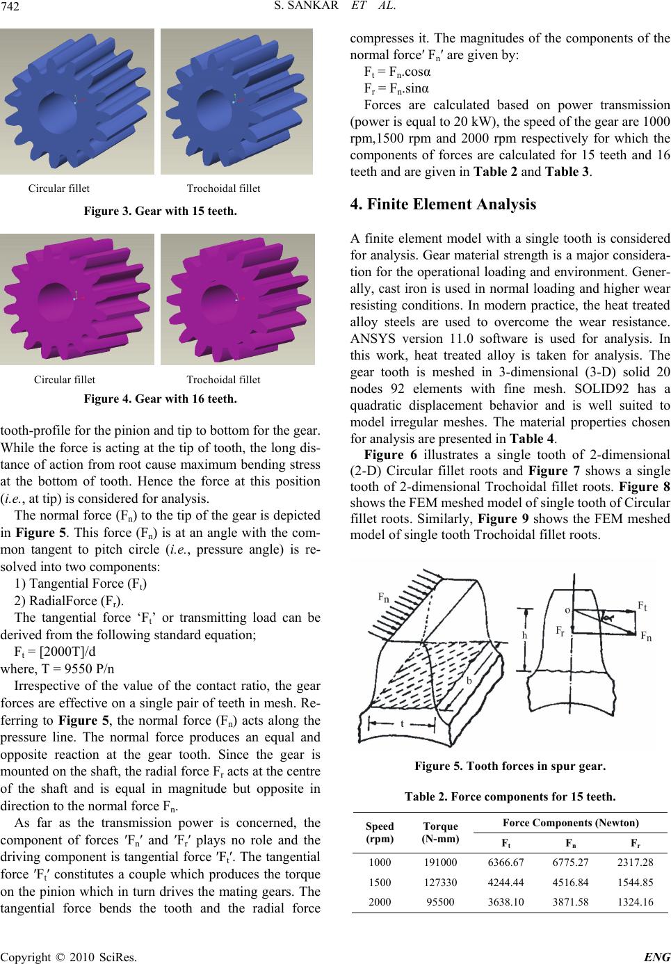 S. SANKAR ET AL. Copyright © 2010 SciRes. ENG 742 Circular fillet Trochoidal fillet Figure 3. Gear with 15 teeth. Circular fillet Trochoidal fillet Figure 4. Gear with 16 teeth. tooth-profile for the pinion and tip to bottom for the gear. While the force is acting at the tip of tooth, the long dis- tance of action from root cause maximum bending stress at the bottom of tooth. Hence the force at this position (i.e., at tip) is considered for analysis. The normal force (Fn) to the tip of the gear is depicted in Figure 5. This force (Fn) is at an angle with the com- mon tangent to pitch circle (i.e., pressure angle) is re- solved into two components: 1) Tangential Force (Ft) 2) RadialForce (Fr). The tangential force ‘Ft’ or transmitting load can be derived from the following standard equation; Ft = [2000T]/d where, T = 9550 P/n Irrespective of the value of the contact ratio, the gear forces are effective on a single pair of teeth in mesh. Re- ferring to Figure 5, the normal force (Fn) acts along the pressure line. The normal force produces an equal and opposite reaction at the gear tooth. Since the gear is mounted on the shaft, the radial force Fr acts at the centre of the shaft and is equal in magnitude but opposite in direction to the normal force Fn. As far as the transmission power is concerned, the component of forces ′Fn′ and ′Fr′ plays no role and the driving component is tangential force ′Ft′. The tangential force ′Ft′ constitutes a couple which produces the torque on the pinion which in turn drives the mating gears. The tangential force bends the tooth and the radial force compresses it. The magnitudes of the components of the normal force′ Fn′ are given by: Ft = Fn.cosα Fr = Fn.sinα Forces are calculated based on power transmission (power is equal to 20 kW), the speed of the gear are 1000 rpm,1500 rpm and 2000 rpm respectively for which the components of forces are calculated for 15 teeth and 16 teeth and are given in Table 2 and Table 3. 4. Finite Element Analysis A finite element model with a single tooth is considered for analysis. Gear material strength is a major considera- tion for the operational loading and environment. Gener- ally, cast iron is used in normal loading and higher wear resisting conditions. In modern practice, the heat treated alloy steels are used to overcome the wear resistance. ANSYS version 11.0 software is used for analysis. In this work, heat treated alloy is taken for analysis. The gear tooth is meshed in 3-dimensional (3-D) solid 20 nodes 92 elements with fine mesh. SOLID92 has a quadratic displacement behavior and is well suited to model irregular meshes. The material properties chosen for analysis are presented in Table 4. Figure 6 illustrates a single tooth of 2-dimensional (2-D) Circular fillet roots and Figure 7 shows a single tooth of 2-dimensional Trochoidal fillet roots. Figure 8 shows the FEM meshed model of single tooth of Circular fillet roots. Similarly, Figure 9 shows the FEM meshed model of single tooth Trochoidal fillet roots. Figure 5. Tooth forces in spur gear. Table 2. Force components for 15 teeth. Force Components (Newton) Speed (rpm) Torque (N-mm) Ft F n F r 1000 191000 6366.67 6775.27 2317.28 1500 127330 4244.44 4516.84 1544.85 2000 95500 3638.10 3871.58 1324.16 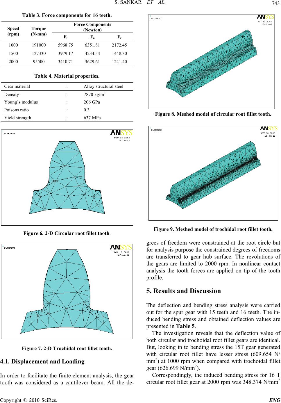 S. SANKAR ET AL. Copyright © 2010 SciRes. ENG 743 Table 3. Force components for 16 teeth. Force Components (Newton) Speed (rpm) Torque (N-mm) Ft F n F r 1000 191000 5968.75 6351.81 2172.45 1500 127330 3979.17 4234.54 1448.30 2000 95500 3410.71 3629.61 1241.40 Table 4. Material properties. Gear material : Alloy structural steel Density : 7870 kg/m3 Young’s modulus : 206 GPa Poisons ratio : 0.3 Yield strength : 637 MPa Figure 6. 2-D Circular root fillet tooth. Figure 7. 2-D Trochidal root fillet tooth. 4.1. Displacement and Loading In order to facilitate the finite element analysis, the gear tooth was considered as a cantilever beam. All the de- Figure 8. Meshed model of circular root fillet tooth. Figure 9. Meshed model of trochidal root fillet tooth. grees of freedom were constrained at the root circle but for analysis purpose the constrained degrees of freedoms are transferred to gear hub surface. The revolutions of the gears are limited to 2000 rpm. In nonlinear contact analysis the tooth forces are applied on tip of the tooth profile. 5. Results and Discussion The deflection and bending stress analysis were carried out for the spur gear with 15 teeth and 16 teeth. The in- duced bending stress and obtained deflection values are presented in Table 5. The investigation reveals that the deflection value of both circular and trochoidal root fillet gears are identical. But, looking in to bending stress the 15T gear generated with circular root fillet have lesser stress (609.654 N/ mm2) at 1000 rpm when compared with trochoidal fillet gear (626.699 N/mm2). Correspondingly, the induced bending stress for 16 T circular root fillet gear at 2000 rpm was 348.374 N/mm2  S. SANKAR ET AL. Copyright © 2010 SciRes. ENG 744 where as it was noticed as 358.114 N/mm2 for 16 T tro- choidal root fillet gear. The bending stress and deflection values taken from FEA results for 15 teeth gear with circular and trochoidal root fillet are depicted in Figure 10. Similarly, the bending stress and deflection values taken from FEA results for 16 teeth gear with circular and trochoidal root fillet are depicted in Figure 11. It is observed from ANSYS study that the 16T gear generated with circular root fillet have lesser stress (328.381 N/mm2) at 1000 rpm when compared with trochoidal fillet gear (558.287 N/mm2). Also, the bending stress Table 5. Deflection and bending stress result. Deflection(mm) Bending Stress (N/mm2) 15 Teeth 16 Teeth 15 Teeth 16 Teeth Speed Trochoidal Circular Trochoidal Circular Trochoidal Circular Trochoidal Circular 1000 0.013343 0.013747 0.013909 0.012407 626.699 609.654 558.287 328.381 1500 0.008895 0.009164 0.009272 0.008271 417.798 406.435 372.192 218.921 2000 0.007624 0.007855 0.007948 0.007090 358.114 348.374 319.021 187.646 15 Teeth - Deflection Trochoidal Fillet Circular Fillet at 1000 rpm 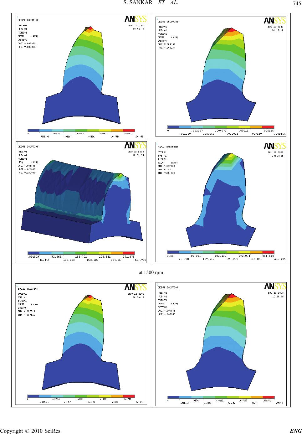 S. SANKAR ET AL. Copyright © 2010 SciRes. ENG 745 at 1500 rpm 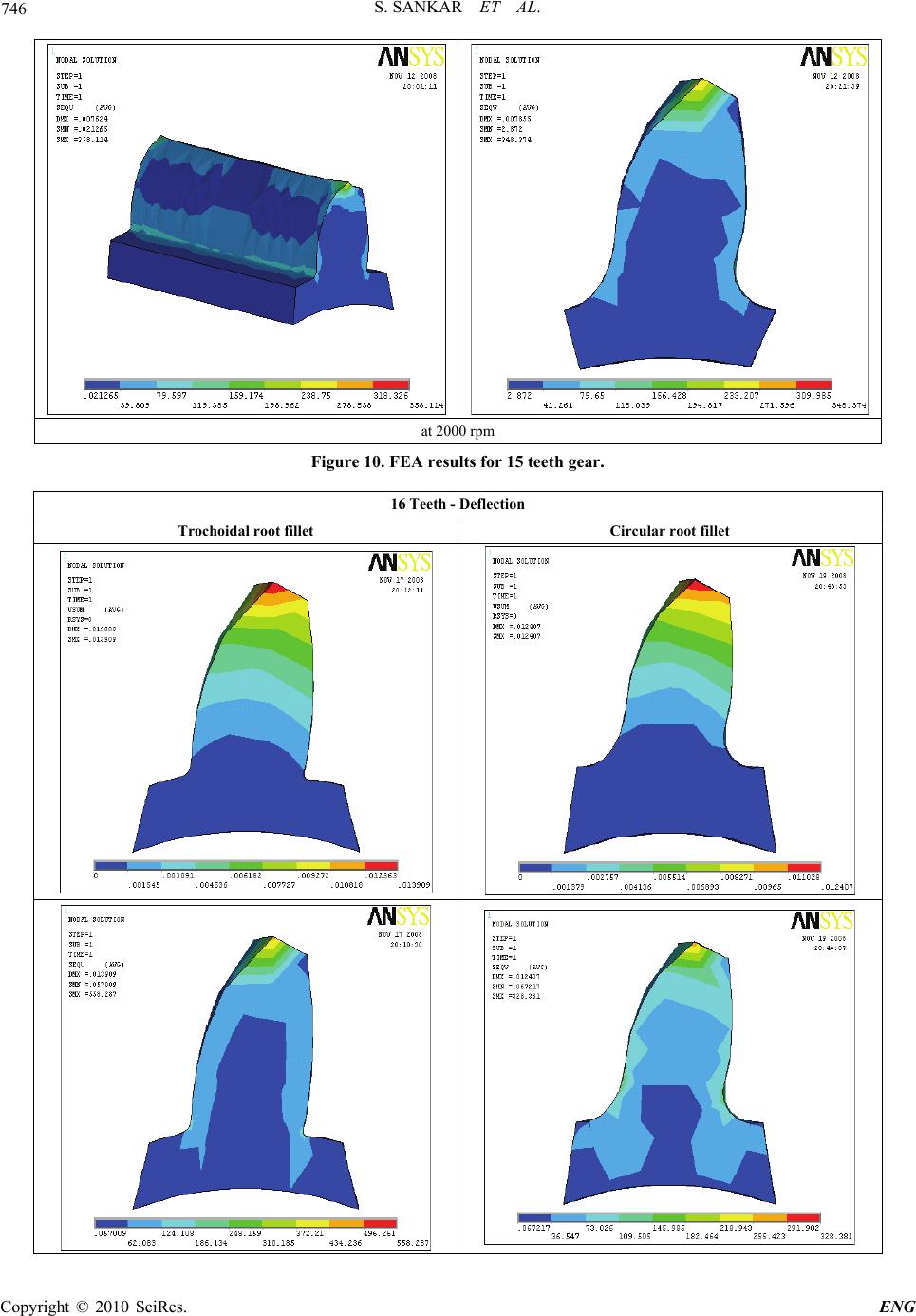 S. SANKAR ET AL. Copyright © 2010 SciRes. ENG 746 at 2000 rpm Figure 10. FEA results for 15 teeth gear. 16 Teeth - Deflection Trochoidal root fillet Circular root fillet 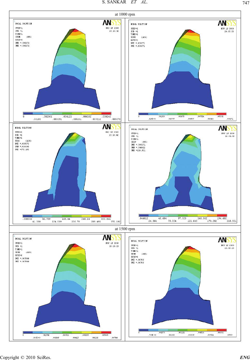 S. SANKAR ET AL. Copyright © 2010 SciRes. ENG 747 at 1000 rpm at 1500 rpm 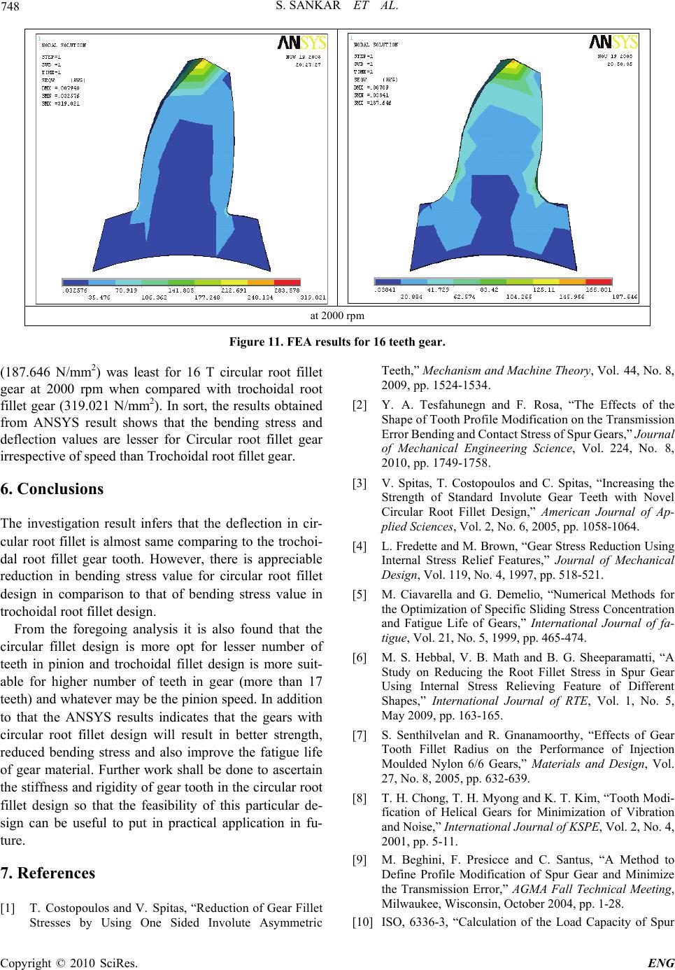 S. SANKAR ET AL. Copyright © 2010 SciRes. ENG 748 at 2000 rpm Figure 11. FEA results for 16 teeth gear. (187.646 N/mm2) was least for 16 T circular root fillet gear at 2000 rpm when compared with trochoidal root fillet gear (319.021 N/mm2). In sort, the results obtained from ANSYS result shows that the bending stress and deflection values are lesser for Circular root fillet gear irrespective of speed than Trochoidal root fillet gear. 6. Conclusions The investigation result infers that the deflection in cir- cular root fillet is almost same comparing to the trochoi- dal root fillet gear tooth. However, there is appreciable reduction in bending stress value for circular root fillet design in comparison to that of bending stress value in trochoidal root fillet design. From the foregoing analysis it is also found that the circular fillet design is more opt for lesser number of teeth in pinion and trochoidal fillet design is more suit- able for higher number of teeth in gear (more than 17 teeth) and whatever may be the pinion speed. In addition to that the ANSYS results indicates that the gears with circular root fillet design will result in better strength, reduced bending stress and also improve the fatigue life of gear material. Further work shall be done to ascertain the stiffness and rigidity of gear tooth in the circular root fillet design so that the feasibility of this particular de- sign can be useful to put in practical application in fu- ture. 7. References [1] T. Costopoulos and V. Spitas, “Reduction of Gear Fillet Stresses by Using One Sided Involute Asymmetric Teeth,” Mechanism and Machine Theory, Vol. 44, No. 8, 2009, pp. 1524-1534. [2] Y. A. Tesfahunegn and F. Rosa, “The Effects of the Shape of Tooth Profile Modification on the Transmission Error Bending and Contact Stress of Spur Gears,” Journal of Mechanical Engineering Science, Vol. 224, No. 8, 2010, pp. 1749-1758. [3] V. Spitas, T. Costopoulos and C. Spitas, “Increasing the Strength of Standard Involute Gear Teeth with Novel Circular Root Fillet Design,” American Journal of Ap- plied Sciences, Vol. 2, No. 6, 2005, pp. 1058-1064. [4] L. Fredette and M. Brown, “Gear Stress Reduction Using Internal Stress Relief Features,” Journal of Mechanical Design, Vol. 119, No. 4, 1997, pp. 518-521. [5] M. Ciavarella and G. Demelio, “Numerical Methods for the Optimization of Specific Sliding Stress Concentration and Fatigue Life of Gears,” International Journal of fa- tigue, Vol. 21, No. 5, 1999, pp. 465-474. [6] M. S. Hebbal, V. B. Math and B. G. Sheeparamatti, “A Study on Reducing the Root Fillet Stress in Spur Gear Using Internal Stress Relieving Feature of Different Shapes,” International Journal of RTE, Vol. 1, No. 5, May 2009, pp. 163-165. [7] S. Senthilvelan and R. Gnanamoorthy, “Effects of Gear Tooth Fillet Radius on the Performance of Injection Moulded Nylon 6/6 Gears,” Materials and Design, Vol. 27, No. 8, 2005, pp. 632-639. [8] T. H. Chong, T. H. Myong and K. T. Kim, “Tooth Modi- fication of Helical Gears for Minimization of Vibration and Noise,” International Journal of KSPE, Vol. 2, No. 4, 2001, pp. 5-11. [9] M. Beghini, F. Presicce and C. Santus, “A Method to Define Profile Modification of Spur Gear and Minimize the Transmission Error,” AGMA Fall Technical Meeting, Milwaukee, Wisconsin, October 2004, pp. 1-28. [10] ISO, 6336-3, “Calculation of the Load Capacity of Spur  S. SANKAR ET AL. Copyright © 2010 SciRes. ENG 749 and Helical Gears-Part 3,” Calculation of Bending Strength, 1996. [11] AGMA, 2101-C95, “Fundamental Rating Factors and Calculation Methods for Involute Spur and Helical Gear (Metric Version),” American Gear Manufacturers Asso- ciation, 1995. [12] H. H. Mabie, C. A. Rogers and C. F. Reinholtz, “Design of Nonstandard Spur Gears Cut by a Hob,” Mechanism and Machine Theory, Vol. 25, No. 6, 1990, pp. 635-644. [13] C. A. Rogers, H. H. Mabie and C. F. Reinholtz, “Design of Spur Gears Generated with Pinion Cutters,” Mecha- nism and Machine Theory, Vol. 25, No. 6, 1990, pp. 623-634. [14] G. Niemann,“Maschinenelemente,” Band 2, Springer, Verlag, 1965. Nomenclature Fn – Normal force P – Rated power Ft – Tangential force d – PCD of gear R – Reaction of shaft n – Speed of the gear in rpm rf – Root Circle of gear T – Transmitted Torque Ss – Arc length at BCD rs – Form Circle of gear FEA – Finite Element Analysis |