Paper Menu >>
Journal Menu >>
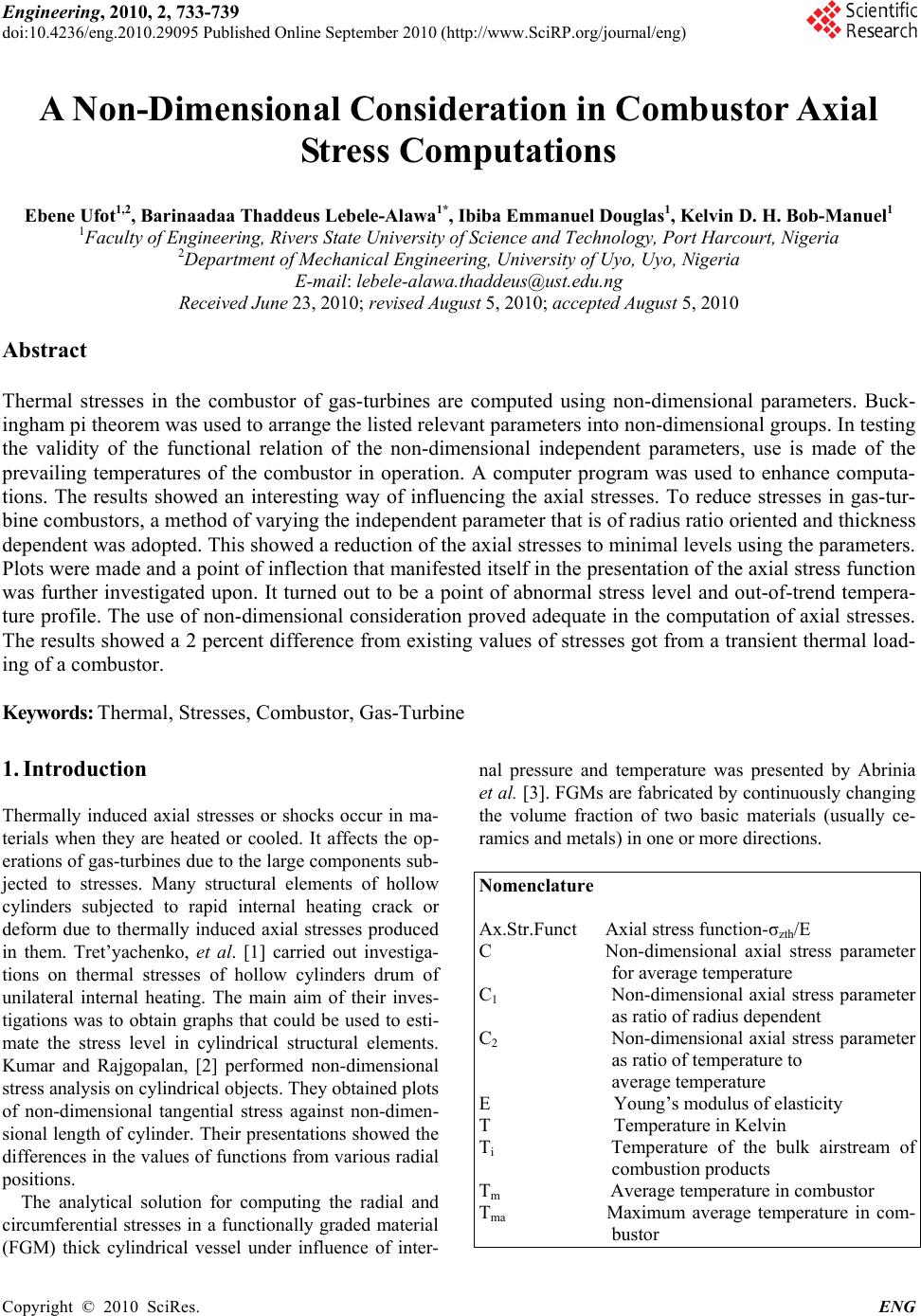 Engineering, 2010, 2, 733-739 doi:10.4236/eng.2010.29095 Published Online September 2010 (http://www.SciRP.org/journal/eng) Copyright © 2010 SciRes. ENG A Non-Dimensional Consideration in Combustor Axial Stress Computations Ebene Ufot1,2, Barinaadaa Thaddeus Lebele-Alawa1*, Ibiba Emmanuel Douglas1, Kelvin D. H. Bob-Manuel1 1Faculty of Engineering, Rivers State University of Science and Technology, Port Harcourt, Nigeria 2Department of Mechanical Engineering, University of Uyo, Uyo, Nigeria E-mail: lebele-alawa.thaddeus@ust.edu.ng Received June 23, 2010; revised August 5, 2010; accepted August 5, 2010 Abstract Thermal stresses in the combustor of gas-turbines are computed using non-dimensional parameters. Buck- ingham pi theorem was used to arrange the listed relevant parameters into non-dimensional groups. In testing the validity of the functional relation of the non-dimensional independent parameters, use is made of the prevailing temperatures of the combustor in operation. A computer program was used to enhance computa- tions. The results showed an interesting way of influencing the axial stresses. To reduce stresses in gas-tur- bine combustors, a method of varying the independent parameter that is of radius ratio oriented and thickness dependent was adopted. This showed a reduction of the axial stresses to minimal levels using the parameters. Plots were made and a point of inflection that manifested itself in the presentation of the axial stress function was further investigated upon. It turned out to be a point of abnormal stress level and out-of-trend tempera- ture profile. The use of non-dimensional consideration proved adequate in the computation of axial stresses. The results showed a 2 percent difference from existing values of stresses got from a transient thermal load- ing of a combustor. Keywords: Thermal, Stresses, Combustor, Gas-Turbine 1. Introduction Thermally induced axial stresses or shocks occur in ma- terials when they are heated or cooled. It affects the op- erations of gas-turbines due to the large components sub- jected to stresses. Many structural elements of hollow cylinders subjected to rapid internal heating crack or deform due to thermally induced axial stresses produced in them. Tret’yachenko, et al. [1] carried out investiga- tions on thermal stresses of hollow cylinders drum of unilateral internal heating. The main aim of their inves- tigations was to obtain graphs that could be used to esti- mate the stress level in cylindrical structural elements. Kumar and Rajgopalan, [2] performed non-dimensional stress analysis on cylindrical objects. They obtained plots of non-dimensional tangential stress against non-dimen- sional length of cylinder. Their presentations showed the differences in the values of functions from various radial positions. The analytical solution for computing the radial and circumferential stresses in a functionally graded material (FGM) thick cylindrical vessel under influence of inter- nal pressure and temperature was presented by Abrinia et al. [3]. FGMs are fabricated by continuously changing the volume fraction of two basic materials (usually ce- ramics and metals) in one or more directions. Nomenclature Ax.Str.Funct Axial stress function-σzth/E C Non-dimensional axial stress parameter for average temperature C1 Non-dimensional axial stress parameter as ratio of radius dependent C2 Non-dimensional axial stress parameter as ratio of temperature to average temperature E Young’s modulus of elasticity T Temperature in Kelvin Ti Temperature of the bulk airstream of combustion products Tm Average temperature in combustor Tma Maximum average temperature in com- bustor 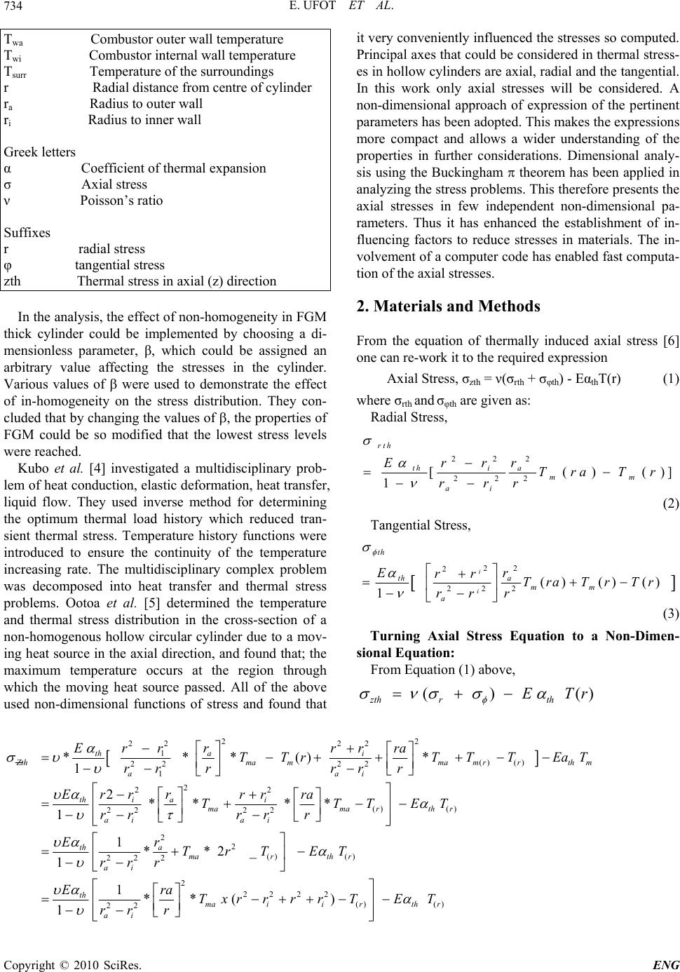 E. UFOT ET AL. Copyright © 2010 SciRes. ENG 734 Twa Combustor outer wall temperature Twi Combustor internal wall temperature Tsurr Temperature of the surroundings r Radial distance from centre of cylinder ra Radius to outer wall ri Radius to inner wall Greek letters α Coefficient of thermal expansion σ Axial stress ν Poisson’s ratio Suffixes r radial stress φ tangential stress zth Thermal stress in axial (z) direction In the analysis, the effect of non-homogeneity in FGM thick cylinder could be implemented by choosing a di- mensionless parameter, β, which could be assigned an arbitrary value affecting the stresses in the cylinder. Various values of were used to demonstrate the effect of in-homogeneity on the stress distribution. They con- cluded that by changing the values of , the properties of FGM could be so modified that the lowest stress levels were reached. Kubo et al. [4] investigated a multidisciplinary prob- lem of heat conduction, elastic deformation, heat transfer, liquid flow. They used inverse method for determining the optimum thermal load history which reduced tran- sient thermal stress. Temperature history functions were introduced to ensure the continuity of the temperature increasing rate. The multidisciplinary complex problem was decomposed into heat transfer and thermal stress problems. Ootoa et al. [5] determined the temperature and thermal stress distribution in the cross-section of a non-homogenous hollow circular cylinder due to a mov- ing heat source in the axial direction, and found that; the maximum temperature occurs at the region through which the moving heat source passed. All of the above used non-dimensional functions of stress and found that it very conveniently influenced the stresses so computed. Principal axes that could be considered in thermal stress- es in hollow cylinders are axial, radial and the tangential. In this work only axial stresses will be considered. A non-dimensional approach of expression of the pertinent parameters has been adopted. This makes the expressions more compact and allows a wider understanding of the properties in further considerations. Dimensional analy- sis using the Buckingham theorem has been applied in analyzing the stress problems. This therefore presents the axial stresses in few independent non-dimensional pa- rameters. Thus it has enhanced the establishment of in- fluencing factors to reduce stresses in materials. The in- volvement of a computer code has enabled fast computa- tion of the axial stresses. 2. Materials and Methods From the equation of thermally induced axial stress [6] one can re-work it to the required expression Axial Stress, σzth = ν(σrth + σφth) - EαthT(r) (1) where σrth and σφth are given as: Radial Stress, 222 222 [()()] 1 rth thi a mm ai Errr Tra Tr rrr (2) Tangential Stress, 2 2 2 22 2( )()() 1 i i th th a mm a Er rr TraTr Tr r rr (3) Turning Axial Stress Equation to a Non-Dimen- sional Equation: From Equation (1) above, () () zth rth E Tr 22 22 22 1 () () 22 22 1 ***()* 1 th ai Z thmammam rrthm aai Errr rr ra TTrTTT EaT rr rr rr 2 22 () () 22 22 2** ** 1 thi ai mamarth r ai ai Errrrrra TTTET r rr rr 2 2 () () 222 1**2_ 1 th a marth r ai Er TrT ET rrr 2 22 2 2 () () 22 1**() 1 th maiirth r ai Era Txr rrrTET r rr  E. UFOT ET AL. Copyright © 2010 SciRes. ENG 735 () 2 2 11 1 th math r ET E T ri ra () 2 2 * 11 r th zthma ma T ETT ri ra (4) Hence, from Equation (2) above, some functional rela- tion must exist in the form of ,() ,,,, ZthZththa imar ErrTT (5) Dimensionless Consideration on Axial Stress. Sorting out the inherent parameters: Forming a table of parameters: Table 1. The Buckingham theorem proves that in a physical problem including n quantities in which there are m di- mensions, the quantities can be arranged into n – m in- dependent dimensionless parameters. Hence some functional relation must exist in the form as expressed in Equation (5) () ,,,, zthzththaimar ErrTT Applying the Buckingham theorem, there are three groups to be found, so Axial Stress, Z th can be more compactly stated as a function of these three non-dimensional parameters [7]. Thus from Equation (5) 1. Zasa nondimensional parameter E (Axial Stress Function) () 2 1 2 0 2. 2 3. 1 4. *1 r ma i a th ma TasC T as C r r TasC Actually, the main three independent dimensionless parameters can be seen as: 0102 ,* * ZCCandCC E But Equation (3) can be written as: 01 2 () () Zth CCr Cr E (6) 3. Results and Discussions The results of the non-dimensional axial stress computa- tions are shown as program results below, and the corre- sponding wall thickness values are given in Table 2. The non-dimensional consideration gave a wider view of the axial stress. In Figure 1 and Figure 2, the values were plotted against a non-dimensional temperature parameter, EU402-AXIAL STRESS FUNCTION_PROGRAM RESULTS VarNr, ra, Twa, Twi 1 38 2549.6 2584.1 T(0), T(1), T(2), T(3), T(4) 2549.6 2558.2 2566.9 2575.5 2584.1 Tm(0), Tm(1), Tm(2), Tm(3), Tm(4) 194.8 176.5 130.2 80.7 27.8 VarNr C1 C2 C0 AxialStress AxialStressFunct:Ax-Str/E 1 3.96 13.09 0 .00 .000000 1 3.96 13.09 0.00345 −6618.35 −.031516 1 3.96 13.14 0 .00 .000000 1 3.96 13.14 0.00345 −6650.44 −.031669 1 3.96 13.18 0 .00 .000000 1 3.96 13.18 0.00345 −6682.52 −.031822 1 3.96 13.22 0 .00 .000000 1 3.96 13.22 0.00345 −6714.61 −.031974 1 3.96 13.27 0 .00 .000000 1 3.96 13.27 0.00345 −6746.69 −.032127  E. UFOT ET AL. Copyright © 2010 SciRes. ENG 736 -0.032 14 -0.032 12 -0.032 1 -0.032 08 -0.032 06 00.00050.0010.0015 0.002 0.0025 0.003 0.0035 0.004 C 0 -Values[-] Non-dimensional Axial Stress[-] σz/E Figure 1. Non-dimensional axial stress versus C0-values. -6 -5 -4 -3 -2 -1 0 00.511.522.533.5 WALL THICKNESS[cm] AXIAL STRESS/C0-Values (TANGENT) σz/C0 Figure 2. Axial stress/C0 (Tangent) versus wall thickness showing a point of inflection at a thickness of 1.44 cm. Table 1. Dimensions of independent parameters for axial stress. S/N Input parameters Dimensions 1 Axial stress, 2 2 2 1 * 1 th Nmm mkg s M L-1 T -2 2 E, 2 2 1 * Nkg m s m M L-1 T -2 3 th 1 K K -1 4 Tma [ K ] K 5 T(r) [ K ] K 6 ra [m] L 7 ri [m] L n - m = 3 Table 2. Axial stress function versus wall thickness. Var.Nr ra r i Wall Thickness Tsurr T i T wa T wi Ax.Str.Fct. σzth(max) 1 38 35 3 620 2620 2549.6 2584.1 −0.032127 5 37 35 2 620 2620 2561.9 2584.7 −0.032106 7 36 35 1 620 2620 2574.0 2585.4 −0.032086 10 35.5 35 0.5 620 2620 2580.0 2585.7 −0.032075 18 35.25 35 0.25 620 2620 2586.0 2586.5 −0.032073 16 (AFAM) 75 74.5 0.25 605 2578 2535.5 2536.0 −0.031447  E. UFOT ET AL. Copyright © 2010 SciRes. ENG 737 CO and against the wall thickness, respectively. In Fig- ure 3 the axial stress function is plotted against the radial nodal positions. All the presentations show an increasing tendency with increased wall thickness. The Figure 4 above shows a method of influencing the stress levels in materials: By increasing the independent parameter, C1, the stress levels can be reduced where C12 2 . 1i a r r In other words, the radial ratio, ri/ra should be increas- ed. In Equation (4), 01 2 / zECCrCr where: () 2 12 0 . 2 1 And, .* 1 r ma i a th ma T CT C r r CT If C1 is to be high, Then the ratio ri/ra must be high i.e., ai rr i.e., ra should be reduced to the lowest value applicable. A table of values can be formed for ri = 35 cm: See Table 3, above. The results for internal wall tem- peratures are presented in Table 4. Table 3. A non-dimensional parameter, C1 by various ex- ternal wall radius of model. ra [cm] ri/ra 2 1i a r r 2 2/1 i a r r 38 0.92 0.1536 3.96 37 0.946 0.1052 5.70 36 0.97 0.055 10.95 35.5 0.986 0.028 21.42 35.25 0.993 0.014 42.86 Table 4. Axial stress function versus internal wall tempera- tures. Time [secs] Twi [K] Axial Stress σzth [MPa] (Ufot, 2010) Axial Stress Function (σzth/E) [-] Axial Stress Function (Present model) 70 2027.8−5820.0 −0.027714 −0.027113 140 2298.2−6351.0 −0.030243 −0.029990 210 2392.4−6531.0 −0.031100 −0.031005 350 2429.9−6601.0 −0.031433 −0.031413 490 2433.0−6607.0 −0.031462 −0.031447 630 2433.3−6608.0 −0.031467 −0.031450 922.12584.1−6746.7 −0.032127 −0.032127 Ax.Fct1 Ax. Fct2 Ax. Fct3 Ax. Fct4 Ax. Fct5 -0.0322 -0.0321 -0.032 -0.0319 -0.0318 -0.0317 -0.0316 -0.0315 -0.0314 0.91 0.920.93 0.94 0.95 0.960.97 0.98 0.9911.01 NODAL(RADIAL) POSITIONS[-] AXIAL STRESS FUNCTION(MAX)[ Ax.Fct1 Ax.Fct1 Ax. Fct2 Ax. Fct3 Ax. Fct4 Ax. Fct5 Figure 3. Axial stress function (Max) versus radial nodal positions radial nodal positions r = ri/ra. 3.96 5.7 10.95 10.95 -0. 0 321 3 -0. 0 321 2 -0. 0 321 1 -0.0321 -0. 0 320 9 -0. 0 320 8 -0. 0 320 7 024681012 C1-Values [-] Non-dimensional Axial Stress [-] σz/E Figure 4. Non-dimensional axial stress versus C1.  E. UFOT ET AL. Copyright © 2010 SciRes. ENG 738 σmax 13 σmax 1 σmax 5 σmax 7 σmax 10 -0.03213 -0.03212 -0.03211 -0. 0321 -0.03209 -0.03208 -0.03207 00.5 11.5 22.5 33.5 Wall Thickness [cm] Axial Stress Function (Max) [-] Series1 σmax1 σmax5 σmax7 σmax10 σmax13 Figure 5. Axial stress function versus wall thickness - showing value position of point of inflection: σmax13. -0. 033 -0. 032 -0. 031 -0.0 3 -0. 029 -0. 028 -0. 027 -0. 026 05001000 1500 20002500 3000 Internal Wall Temperatures[K] Axial Stress Function[-] EU-2010 present model Figure 6. Axial stress function versus internal wall temperatures. Figure 1 is a presentation of a non-dimensional axial stress against C0-values. The non-dimensional tempera- ture parameter, C0, is the maximum average temperature dependent parameter. The stress shows a tendency of increasing with the C0. That means to reduce the stress in the material, the maximum average temperature in the material must be reduced. And this maximum tempera- ture is noted to be increasing with wall thickness. There- fore, in the final analysis, the wall thickness for minimal thermal stresses should be as small as applicable. Figure 2 shows a point of Inflection in the presenta- tion of axial stress/C0 with wall thickness. Further con- sideration of this point of Inflection occurring at a wall thickness of 1.44 cm, shows an abnormal trends of tem- peratures and stresses in the material. In a cross-sectional view of the non-dimensional stress profile in the material shows linear relationship with the non-dimensional radial positions. In Figure 4, a non-dimensional axial stress is shown varying against C1-values. The indicated C1-value on the trend is showing that with very high values of C1 the stress tends minimal. It is a definite method of influ- encing the stress levels in materials. It can be shown with Figure 5 that to obtain very minimal axial stresses in material, the wall thickness should be reduced. As is shown in the figure, the stress values are reducing as the wall thickness is reduced. Figure 6 shows that the Axial Stress Function increases with increased internal wall temperatures. 4. Conclusions The work is very adequate in computing the thermal ax- ial stress in combustors and cylindrical pipes at the in- stance of known wall surface temperatures. With the Non-dimensional consideration in the combustor axial Stress computation it is possible to indicate ways of mi- nimizing the thermal axial stress in the material. 5. References [1] G. N. Tret’yachenko, S. Karpinos and L. E. Kiyashko, “Thermal Stress State of Hollow Cylinders during Uni- lateral Internal Heating,” UDC 539.319.624.074.4, 1976. [2] I. J. Kumar and D. Rajgopalan, “Thermal Stresses in a Hollow Cylinder Due to a Sinusoidal Surface Heating Source,” V. R. Thiruvenkatachar, F.N.I. Defence Science Laboratory, Delhi 6 I, 1969. [3] K. Abrinia, H. Naee, F. Sadeghi and F. Djavanroodi, “New Analysis for the FGM Thick Cylinders under Combined Pressure and Temperature Loading,” © 2008 Science Publications Tehran, Amirabad Shomali St., Te- hran, Iran 852, 2008. [4] S. Kubo, K. Uchida, T. Ishizaka and S. Ioka, “Determina- tion of the Optimum Temperature History of Inlet Water for Minimizing Thermal Stresses in a Pipe by Multiphys- ics Inverse Analysis,” Journal of Physics: Conference Se- ries, Vol. 135, 2008, p. 012058. [5] Y. Ootao, T. Akai and Y. Tanigawa, “Three-Dimensional  E. UFOT ET AL. Copyright © 2010 SciRes. ENG 739 Transient Thermal Stress Analysis of a Non-Homoge- neous Hollow Circular Cylinder Due to a Moving Heat Source in the Axial Direction,” Journal of Thermal Stresses, Vol. 18, No. 5, 1995, pp. 497-512. [6] S. Fronius and G. Trankner, “Taschenbuch Maschinenbau, Band 1/īī Grundlagen,” 3rd Edition, VEB Verlag Technik, Berlin, 1975. [7] E. Ufot, “Modeling Thermal Stresses in the Combustor of Gas Turbine,” Ph.D. Dissertation, Rivers State University of Science and Technology, Port Harcourt, 2010. |