Paper Menu >>
Journal Menu >>
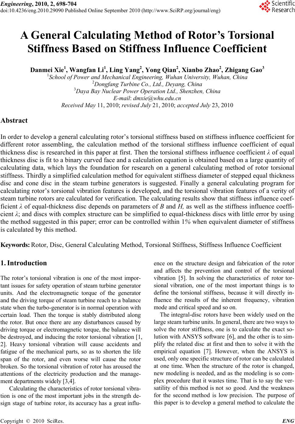 Engineering, 2010, 2, 698-704 doi:10.4236/eng.2010.29090 Published Online September 2010 (http://www.SciRP.org/journal/eng) Copyright © 2010 SciRes. ENG A General Calculating Method of Rotor’s Torsional Stiffness Based on Stiffness Influence Coefficient Danmei Xie1, Wangfan Li1, Ling Yang2, Yong Qian2, Xianbo Zhao2, Zhigang Gao3 1School of Power and Mechanical Engineering, Wuhan University, Wuhan, China 2Dongfang Turbine Co., Ltd., Deyang, China 3Daya Bay Nuclear Power Operation Ltd., Shenzhen, China E-mail: dmxie@whu.edu.cn Received May 11, 2010; revised July 21, 2010; accepted July 23, 2010 Abstract In order to develop a general calculating rotor’s torsional stiffness based on stiffness influence coefficient for different rotor assembling, the calculation method of the torsional stiffness influence coefficient of equal thickness disc is researched in this paper at first. Then the torsional stiffness influence coefficient λ of equal thickness disc is fit to a binary curved face and a calculation equation is obtained based on a large quantity of calculating data, which lays the foundation for research on a general calculating method of rotor torsional stiffness. Thirdly a simplified calculation method for equivalent stiffness diameter of stepped equal thickness disc and cone disc in the steam turbine generators is suggested. Finally a general calculating program for calculating rotor’s torsional vibration features is developed, and the torsional vibration features of a verity of steam turbine rotors are calculated for verification. The calculating results show that stiffness influence coef- ficient λ of equal-thickness disc depends on parameters of B and H, as well as the stiffness influence coeffi- cient λ; and discs with complex structure can be simplified to equal-thickness discs with little error by using the method suggested in this paper; error can be controlled within 1% when equivalent diameter of stiffness is calculated by this method. Keywords: Rotor, Disc, General Calculating Method, Torsional Stiffness, Stiffness Influence Coefficient 1. Introduction The rotor’s torsional vibration is one of the most impor- tant issues for safety operation of steam turbine generator units. And the electromagnetic torque of the generator and the driving torque of steam turbine reach to a balance state when the turbo-generator is in normal operation with certain load. Then the torque is stably distributed along the rotor. But once there are any disturbances caused by driving torque or electromagnetic torque, the balance will be destroyed, and inducing the rotor torsional vibration [1, 2]. Heavy torsional vibration will cause accidents and fatigue of the mechanical parts, so as to shorten the life span of the rotor, and even worse will cause the rotor broken. So the torsional vibration of rotor has aroused the attentions of the electricity production and the manage- ment departments widely [3,4]. Calculating the characteristics of rotor torsional vibra- tion is one of the most important jobs in the strength de- sign stage of turbine rotor, its accuracy has a great influ- ence on the structure design and fabrication of the rotor and affects the prevention and control of the torsional vibration [5]. In solving the characteristics of rotor tor- sional vibration, one of the most important things is to define the torsional stiffness, because it will directly in- fluence the results of the inherent frequency, vibration mode and critical speed and so on. The integral-disc rotors have been widely used on the large steam turbine units. In general, there are two ways to solve the rotor stiffness, one is to calculate the exact so- lution with ANSYS software [6], and the other is to sim- plify the related disc at first and then to solve it with the empirical equation [7]. However, when the ANSYS is used, only one specific structure of rotor can be calculated at one time. When the structure of the rotor is changed, new modeling is needed, and as the modeling is so com- plex procedure that it wastes time. That is to say the ver- satility of this method is not so good. And the weakness for the second method is low precision. The purpose of this paper is to develop a general method to calculate the 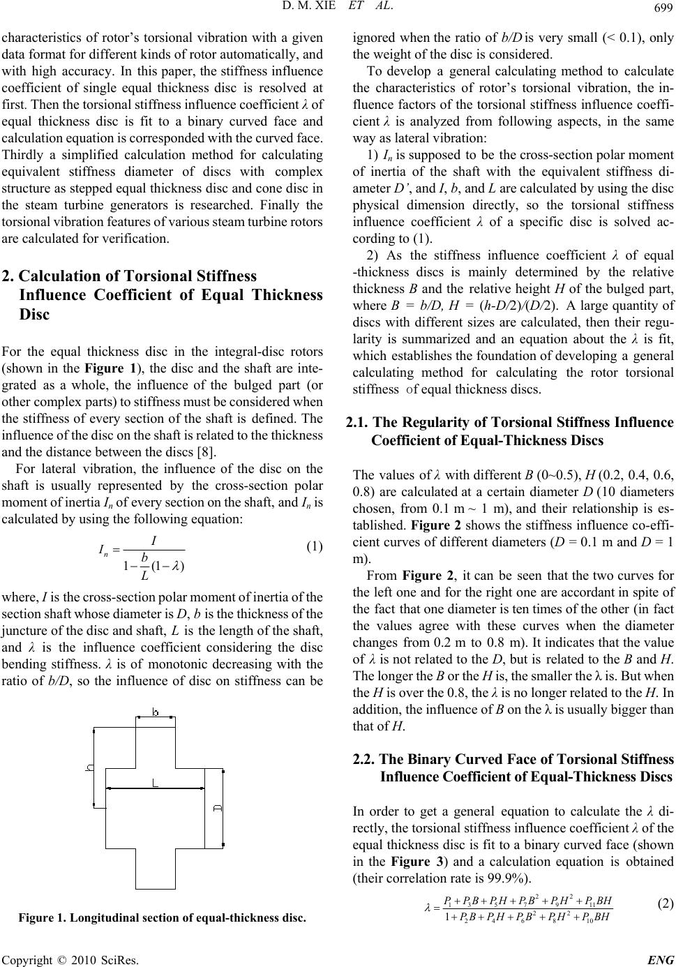 D. M. XIE ET AL. Copyright © 2010 SciRes. ENG 699 characteristics of rotor’s torsional vibration with a given data format for different kinds of rotor automatically, and with high accuracy. In this paper, the stiffness influence coefficient of single equal thickness disc is resolved at first. Then the torsional stiffness influence coefficient λ of equal thickness disc is fit to a binary curved face and calculation equation is corresponded with the curved face. Thirdly a simplified calculation method for calculating equivalent stiffness diameter of discs with complex structure as stepped equal thickness disc and cone disc in the steam turbine generators is researched. Finally the torsional vibration features of various steam turbine rotors are calculated for verification. 2. Calculation of Torsional Stiffness Influence Coefficient of Equal Thickness Disc For the equal thickness disc in the integral-disc rotors (shown in the Figure 1), the disc and the shaft are inte- grated as a whole, the influence of the bulged part (or other complex parts) to stiffness must be considered when the stiffness of every section of the shaft is defined. The influence of the disc on the shaft is related to the thickness and the distance between the discs [8]. For lateral vibration, the influence of the disc on the shaft is usually represented by the cross-section polar moment of inertia In of every section on the shaft, and In is calculated by using the following equation: 1(1) n II b L (1) where, I is the cross-section polar moment of inertia of the section shaft whose diameter is D, b is the thickness of the juncture of the disc and shaft, L is the length of the shaft, and λ is the influence coefficient considering the disc bending stiffness. λ is of monotonic decreasing with the ratio of b/D, so the influence of disc on stiffness can be Figure 1. Longitudinal section of equal-thickness disc. ignored when the ratio of b/D is very small (< 0.1), only the weight of the disc is considered. To develop a general calculating method to calculate the characteristics of rotor’s torsional vibration, the in- fluence factors of the torsional stiffness influence coeffi- cient λ is analyzed from following aspects, in the same way as lateral vibration: 1) In is supposed to be the cross-section polar moment of inertia of the shaft with the equivalent stiffness di- ameter D’, and I, b, and L are calculated by using the disc physical dimension directly, so the torsional stiffness influence coefficient λ of a specific disc is solved ac- cording to (1). 2) As the stiffness influence coefficient λ of equal -thickness discs is mainly determined by the relative thickness B and the relative height H of the bulged part, where B = b/D, H = (h-D/2)/(D/2). A large quantity of discs with different sizes are calculated, then their regu- larity is summarized and an equation about the λ is fit, which establishes the foundation of developing a general calculating method for calculating the rotor torsional stiffness of equal thickness discs. 2.1. The Regularity of Torsional Stiffness Influence Coefficient of Equal-Thickness Discs The values of λ with different B (0~0.5), H (0.2, 0.4, 0.6, 0.8) are calculated at a certain diameter D (10 diameters chosen, from 0.1 m ~ 1 m), and their relationship is es- tablished. Figure 2 shows the stiffness influence co-effi- cient curves of different diameters (D = 0.1 m and D = 1 m). From Figure 2, it can be seen that the two curves for the left one and for the right one are accordant in spite of the fact that one diameter is ten times of the other (in fact the values agree with these curves when the diameter changes from 0.2 m to 0.8 m). It indicates that the value of λ is not related to the D, but is related to the B and H. The longer the B or the H is, the smaller the λ is. But when the H is over the 0.8, the λ is no longer related to the H. In addition, the influence of B on the λ is usually bigger than that of H. 2.2. The Binary Curved Face of Torsional Stiffness Influence Coefficient of Equal-Thickness Discs In order to get a general equation to calculate the λ di- rectly, the torsional stiffness influence coefficient λ of the equal thickness disc is fit to a binary curved face (shown in the Figure 3) and a calculation equation is obtained (their correlation rate is 99.9%). 22 13 57911 22 24 6810 1 P PBPHPBPHP BH P BPHPB PHPBH (2) 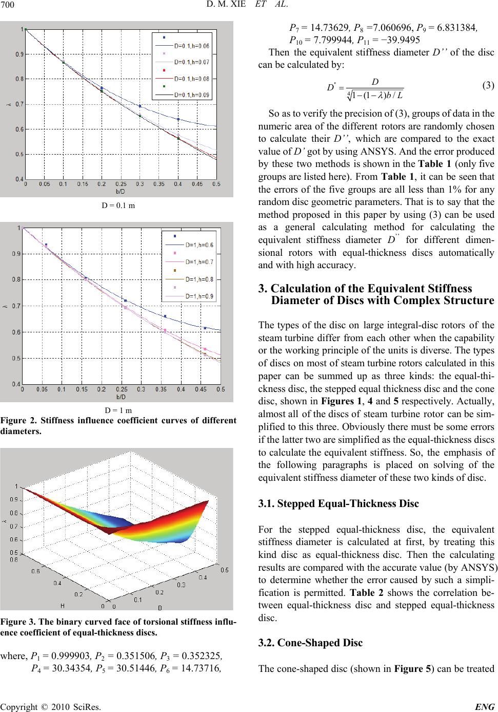 D. M. XIE ET AL. Copyright © 2010 SciRes. ENG 700 D = 0.1 m D = 1 m Figure 2. Stiffness influence coefficient curves of different diameters. Figure 3. The binary curved face of torsional stiffness influ- ence coefficient of equal-thickness discs. where, P1 = 0.999903, P2 = 0.351506, P3 = 0.352325, P 4 = 30.34354, P5 = 30.51446, P6 = 14.73 716 , P 7 = 14.73629, P8 =7.060696, P9 = 6.831384, P 10 = 7.799944, P11 = −39.9495 Then the equivalent stiffness diameter D’’ of the disc can be calculated by: '' 41(1 )/ D DbL (3) So as to verify the precision of (3), groups of data in the numeric area of the different rotors are randomly chosen to calculate their D’’, which are compared to the exact value of D’ got by using ANSYS. And the error produced by these two methods is shown in the Table 1 (only five groups are listed here). From Table 1, it can be seen that the errors of the five groups are all less than 1% for any random disc geometric parameters. That is to say that the method proposed in this paper by using (3) can be used as a general calculating method for calculating the equivalent stiffness diameter D’’ for different dimen- sional rotors with equal-thickness discs automatically and with high accuracy. 3. Calculation of the Equivalent Stiffness Diameter of Discs with Complex Structure The types of the disc on large integral-disc rotors of the steam turbine differ from each other when the capability or the working principle of the units is diverse. The types of discs on most of steam turbine rotors calculated in this paper can be summed up as three kinds: the equal-thi- ckness disc, the stepped equal thickness disc and the cone disc, shown in Figures 1, 4 and 5 respectively. Actually, almost all of the discs of steam turbine rotor can be sim- plified to this three. Obviously there must be some errors if the latter two are simplified as the equal-thickness discs to calculate the equivalent stiffness. So, the emphasis of the following paragraphs is placed on solving of the equivalent stiffness diameter of these two kinds of disc. 3.1. Stepped Equal-Thickness Disc For the stepped equal-thickness disc, the equivalent stiffness diameter is calculated at first, by treating this kind disc as equal-thickness disc. Then the calculating results are compared with the accurate value (by ANSYS) to determine whether the error caused by such a simpli- fication is permitted. Table 2 shows the correlation be- tween equal-thickness disc and stepped equal-thickness disc. 3.2. Cone-Shaped Disc The cone-shaped disc (shown in Figure 5) can be treated 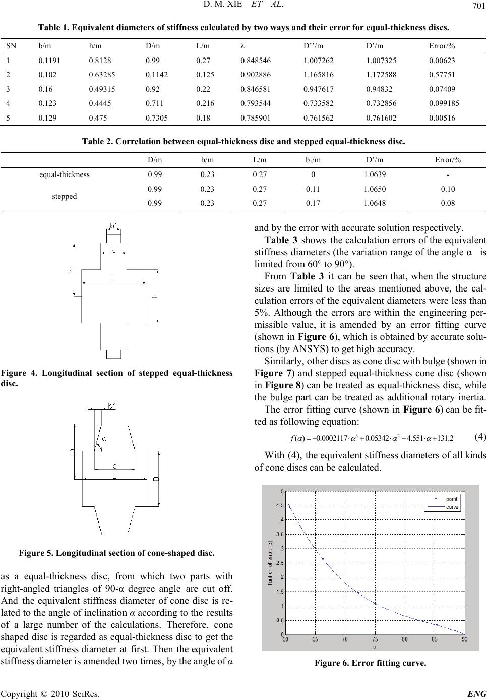 D. M. XIE ET AL. Copyright © 2010 SciRes. ENG 701 Table 1. Equivalent diameters of stiffness calculated by two ways and their error for equal-thickness discs. SN b/m h/m D/m L/m λ D’’/m D’/m Error/% 1 0.1191 0.8128 0.99 0.27 0.848546 1.007262 1.007325 0.00623 2 0.102 0.63285 0.1142 0.125 0.902886 1.165816 1.172588 0.57751 3 0.16 0.49315 0.92 0.22 0.846581 0.947617 0.94832 0.07409 4 0.123 0.4445 0.711 0.216 0.793544 0.733582 0.732856 0.099185 5 0.129 0.475 0.7305 0.18 0.785901 0.761562 0.761602 0.00516 Table 2. Correlation between equal-thickness disc and stepped equal-thickness disc. D/m b/m L/m b1/m D’/m Error/% equal-thickness 0.99 0.23 0.27 0 1.0639 - 0.99 0.23 0.27 0.11 1.0650 0.10 stepped 0.99 0.23 0.27 0.17 1.0648 0.08 Figure 4. Longitudinal section of stepped equal-thickness disc. Figure 5. Longitudinal section of cone-shaped disc. as a equal-thickness disc, from which two parts with right-angled triangles of 90-α degree angle are cut off. And the equivalent stiffness diameter of cone disc is re- lated to the angle of inclination α according to the results of a large number of the calculations. Therefore, cone shaped disc is regarded as equal-thickness disc to get the equivalent stiffness diameter at first. Then the equivalent stiffness diameter is amended two times, by the angle of α and by the error with accurate solution respectively. Table 3 shows the calculation errors of the equivalent stiffness diameters (the variation range of the angle α is limited from 60° to 90°). From Table 3 it can be seen that, when the structure sizes are limited to the areas mentioned above, the cal- culation errors of the equivalent diameters were less than 5%. Although the errors are within the engineering per- missible value, it is amended by an error fitting curve (shown in Figure 6), which is obtained by accurate solu- tions (by ANSYS) to get high accuracy. Similarly, other discs as cone disc with bulge (shown in Figure 7) and stepped equal-thickness cone disc (shown in Figure 8) can be treated as equal-thickness disc, while the bulge part can be treated as additional rotary inertia. The error fitting curve (shown in Figure 6) can be fit- ted as following equation: 32 ( )0.00021170.053424.551131.2f (4) With (4), the equivalent stiffness diameters of all kinds of cone discs can be calculated. Figure 6. Error fitting curve. 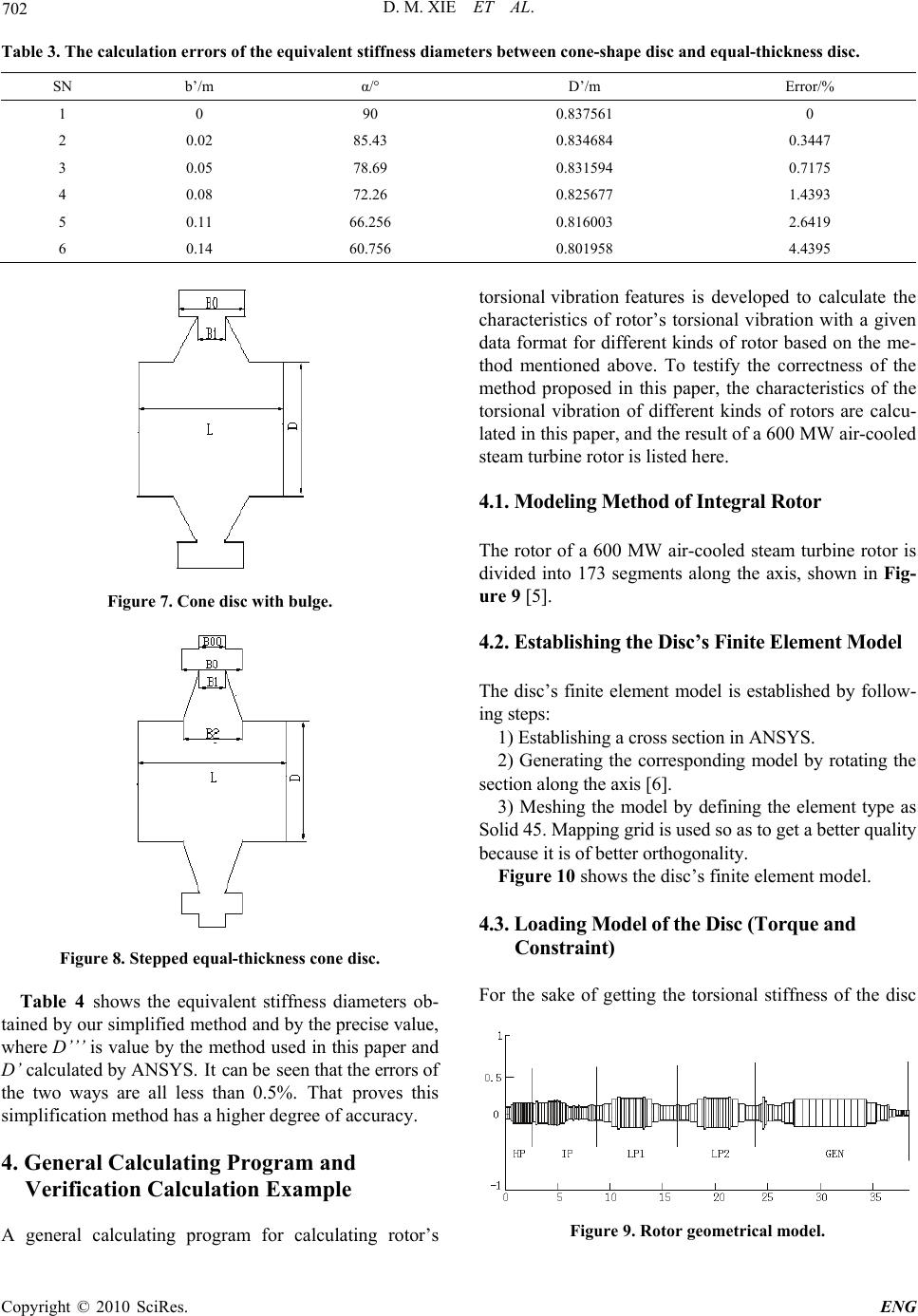 D. M. XIE ET AL. Copyright © 2010 SciRes. ENG 702 Table 3. The calculation errors of the equivalent stiffness diameters between cone-shape disc and equal-thickness disc. SN b’/m α/° D’/m Error/% 1 0 90 0.837561 0 2 0.02 85.43 0.834684 0.3447 3 0.05 78.69 0.831594 0.7175 4 0.08 72.26 0.825677 1.4393 5 0.11 66.256 0.816003 2.6419 6 0.14 60.756 0.801958 4.4395 Figure 7. Cone disc with bulge. Figure 8. Stepped equal-thickness cone disc. Table 4 shows the equivalent stiffness diameters ob- tained by our simplified method and by the precise value, where D’’’ is value by the method used in this paper and D’ calculated by ANSYS. It can be seen that the errors of the two ways are all less than 0.5%. That proves this simplification method has a higher degree of accuracy. 4. General Calculating Program and Verification Calculation Example A general calculating program for calculating rotor’s torsional vibration features is developed to calculate the characteristics of rotor’s torsional vibration with a given data format for different kinds of rotor based on the me- thod mentioned above. To testify the correctness of the method proposed in this paper, the characteristics of the torsional vibration of different kinds of rotors are calcu- lated in this paper, and the result of a 600 MW air-cooled steam turbine rotor is listed here. 4.1. Modeling Method of Integral Rotor The rotor of a 600 MW air-cooled steam turbine rotor is divided into 173 segments along the axis, shown in Fig- ure 9 [5]. 4.2. Establishing the Disc’s Finite Element Model The disc’s finite element model is established by follow- ing steps: 1) Establishing a cross section in ANSYS. 2) Generating the corresponding model by rotating the section along the axis [6]. 3) Meshing the model by defining the element type as Solid 45. Mapping grid is used so as to get a better quality because it is of better orthogonality. Figure 10 shows the disc’s finite element model. 4.3. Loading Model of the Disc (Torque and Constraint) For the sake of getting the torsional stiffness of the disc Figure 9. Rotor geometrical model. 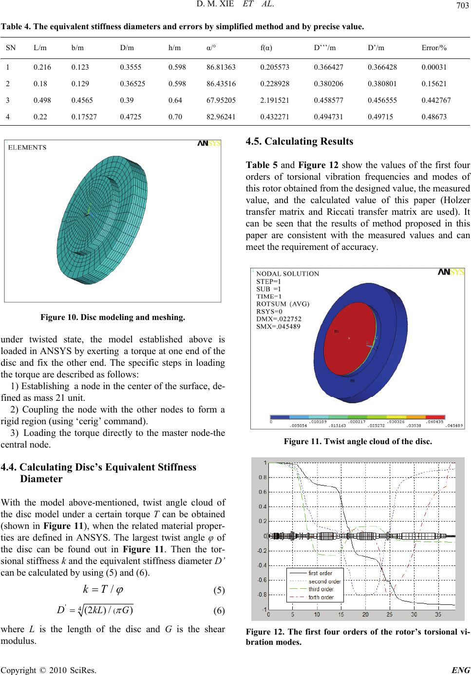 D. M. XIE ET AL. Copyright © 2010 SciRes. ENG 703 Table 4. The equivalent stiffness diameters and errors by simplified method and by precise value. SN L/m b/m D/m h/m α/° f(α) D’’’/m D’/m Error/% 1 0.216 0.123 0.3555 0.598 86.81363 0.205573 0.366427 0.366428 0.00031 2 0.18 0.129 0.36525 0.598 86.43516 0.228928 0.380206 0.380801 0.15621 3 0.498 0.4565 0.39 0.64 67.95205 2.191521 0.458577 0.456555 0.442767 4 0.22 0.17527 0.4725 0.70 82.96241 0.432271 0.494731 0.49715 0.48673 Figure 10. Disc modeling and meshing. under twisted state, the model established above is loaded in ANSYS by exerting a torque at one end of the disc and fix the other end. The specific steps in loading the torque are described as follows: 1) Establishing a node in the center of the surface, de- fined as mass 21 unit. 2) Coupling the node with the other nodes to form a rigid region (using ‘cerig’ command). 3) Loading the torque directly to the master node-the central node. 4.4. Calculating Disc’s Equivalent Stiffness Diameter With the model above-mentioned, twist angle cloud of the disc model under a certain torque T can be obtained (shown in Figure 11), when the related material proper- ties are defined in ANSYS. The largest twist angle φ of the disc can be found out in Figure 11. Then the tor- sional stiffness k and the equivalent stiffness diameter D’ can be calculated by using (5) and (6). kT (5) '4((2) /)kL GD (6) where L is the length of the disc and G is the shear modulus. 4.5. Calculating Results Table 5 and Figure 12 show the values of the first four orders of torsional vibration frequencies and modes of this rotor obtained from the designed value, the measured value, and the calculated value of this paper (Holzer transfer matrix and Riccati transfer matrix are used). It can be seen that the results of method proposed in this paper are consistent with the measured values and can meet the requirement of accuracy. Figure 11. Twist angle cloud of the disc. Figure 12. The first four orders of the rotor’s torsional vi- bration modes.  D. M. XIE ET AL. Copyright © 2010 SciRes. ENG 704 Table 5. The first four orders of the rotor’s torsional vibra- tion frequencies* /Hz. Order 1 2 3 4 designed value 15.03 25.95 30.04 120.3 Measured value 15.3 26.1 30.55 - Holzer 15.2 26.2 31.8 121.6 Calculated value Riccati 15.3 26.3 31.8 124.5 5. Conclusions To develop a general method to calculate the characteris- tics of rotor’s torsional vibration by using data under given format for different kinds of rotor automatically, the stiffness influence coefficient of single equal thick- ness disc is resolved at first. Then the torsional stiffness influence coefficient λ of equal thickness disc is fit to a binary curved face and a calculation equation is obtained based on this curved face. In addition, a simplified cal- culation method for calculating equivalent stiffness di- ameter of discs with complex structure, such as stepped equal thickness disc and cone disc, is proposed. Follow- ing conclusions can be drawn from this paper: 1) The stiffness influence coefficient λ of equal-thi- ckness disc depends on relative thickness B and the rela- tive height H, but not with b and h. And the influence of B on λ is greater than H. 2) Discs with complex structure can be simplified to equal-thickness disc with little error by using the method suggested in this paper, and the error can be control within 1%. 3) The general calculating program developed in this paper is verified to have a universal property and with a reasonable accuracy. 6. Acknowledgements This work is supported by Dongfang Turbine Co., Ltd. in China. 7. References [1] W. F. Li, D. M. Xie, et al., “Calculation of Rotor’s Tor- sional Vibration Characteristics Based on Equivalent Diameter of Stiffness,” Asia-Pacific Power and Energy En- gineering Conference (APPEEC 2010), Chengdu, 2010. [2] W. X. Shi, “Turbine Vibration,” Water Conservancy and Electric Power Press, Beijing, 1991. [3] H. T. Sun, “Approach to Torsional Vibration of Shaft System for High-Capacity Turbo-Generations,” Thermal Power Generation, Vol. 33, No. 1, 2004, pp. 42-44. [4] D. N. Walker, S. L. Adams and R. J. Placek, “Torsional Vibration and Fatigue of Turbine Generator Shafts,” IEEE Transactions on Power Apparatus and Systems, Vol. 100, No. 11, 1981, pp. 4373-4380. [5] Y. L. Li, “Study on Torsional Vibration Characteristics of Turbine Rotor with Cracks Based on ANSYS,” Wuhan University, Wuhan, 2008. [6] L. L. Dang, Z. Y. Weng and G. L. Xu, “Research in Equivalent Rigidity of Rotor Vibration,” Mechanical En- gineer, No. 4, 2009, pp. 89-91. [7] D. M. Xie, C. Dong and Z. H. Liu, “The Torsional Rigid- ity of a Shafting Specific Structure and its Effect on the Torsional Vibration Characteristics,” Thermal Power En- gineering, Vol. 22, No. 2, 2007, pp. 146-148. [8] H. Y. Wu, “Structure and Strength Calculation of Turbine Parts,” Machinery Industry Press, Beijing, 1982. |