 Circuits and Systems, 2013, 4, 75-82 http://dx.doi.org/10.4236/cs.2013.41012 Published Online January 2013 (http://www.scirp.org/journal/cs) New Hybrid Digital Circuit Design Techniques for Reducing Subthreshold Leakage Power in Standby Mode Manish Kumar1, Md. Anwar Hussain1, Sajal K. Paul2 1Department of ECE, North Eastern Regional Institute of Science & Technology, Nirjuli, Arunachal Pradesh, India 2Department of Electronics Engineering, Indian School of Mines, Dhanbad, Jharkhand, India Email: mkr@nerist.ac.in, ah@nerist.ac.in, sajalkpaul@rediffmail.com Received October 10, 2012; revised November 10, 2012; accepted November 17, 2012 ABSTRACT In this paper, four new hybrid digital circuit design techniques, namely, hybrid multi-threshold CMOS complete stack technique, hybrid multi-threshold CMOS partial stack technique, hybrid super cutoff complete stack technique and hy- brid super cutoff partial stack technique, have been proposed to reduce the subthreshold leakage power dissipation in standby modes. Techniques available in literature are compared with our proposed hybrid circuit design techniques. Performance parameters such as subthreshold leakage power dissipation in active and standby modes, dynamic power dissipation and propagation delay, are compared using existing and proposed hybrid techniques for a two input AND gate. Reduction of subthreshold leakage power dissipation in standby mode is given more importance, in comparison with the other circuit design performance parameters. It is found that there is reduction in subthreshold leakage power dissipation in standby and active modes by 3.5× and 1.15× respectively using the proposed hybrid super cutoff com- plete stack technique as compared to the existing multi-threshold CMOS (MTCMOS) technique. Also a saving of 2.50× and 1.04× in subthreshold leakage power dissipation in standby and active modes respectively were observed using hybrid super cutoff complete stack technique as compared to the existing super cutoff CMOS (SCCMOS) technique. The proposed hybrid super cutoff stack technique proved to perform better in terms of subthreshold leakage power dis- sipation in standby mode in comparison with other techniques. Simulation results using Microwind EDA tool in 65 nm CMOS technology is provided in this paper. Keywords: Subthreshold Leakage Power; Standby Mode; Active Mode; Propagation Delay 1. Introduction Design of low power circuit is necessary for portable electronic devices that are powered by batteries as in- creased power dissipation reduces the battery lifetime. Low power dissipation by MOS transistors and its small size for greater integration capacity are the major factors behind shifting in technology from BJTs to MOSFETs. High power dissipation is one of the major challenges of integrated circuit design in deep submicron and nano- scale technologies [1-5]. The demand for higher func- tions with higher performance and lower power dissipa- tion initiates the scaling of MOS transistors in every technology generations. The contribution of dynamic power in the overall power dissipation decreases with the scaling of MOS transistors. Leakage power is expected to increase 32 times per device by the year 2020 [6]. Re- duction of the supply voltage, VDD is considered as the most effective method to reduce the dynamic power, which is directly proportional to the square of the supply voltage, VDD. In order to maintain the same performance, threshold voltage of the transistor is also reduced with the scaling of the supply voltage. However, subthreshold leakage current increases exponentially with the reduce- tion of the threshold voltage of the MOS transistor, mak- ing it critical for low voltage digital integrated circuit design. Scaling of transistors in every technology genera- tions also lead to increase in the subthreshold leakage current. With rapid scaling in technology, the increase in leakage current has made leakage power a significant part in the overall power dissipation in both active and standby modes. The major components of leakage power dissipation are subthreshold leakage, gate leakage, gate induced drain leakage, and forward biased diode leakage [7]. Subthreshold leakage dominates the other leakage components in deep submicron and nanoscale technolo- gies. Threshold voltage of transistors used in design of digital circuits should be adjusted for maximum saving in the leakage power dissipation. Circuit techniques play a very important role to control the subthreshold leakage power dissipation in both active and standby modes. Al- ready some techniques, such as Multi-threshold CMOS C opyright © 2013 SciRes. CS 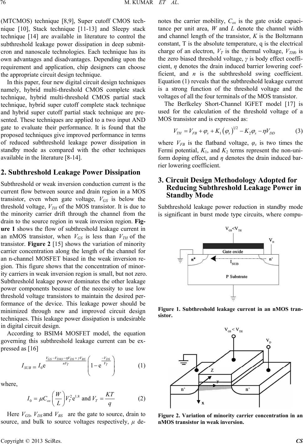 M. KUMAR ET AL. 76 (MTCMOS) technique [8,9], Super cutoff CMOS tech- nique [10], Stack technique [11-13] and Sleepy stack technique [14] are available in literature to control the subthreshold leakage power dissipation in deep submit- cron and nanoscale technologies. Each technique has its own advantages and disadvantages. Depending upon the requirement and application, chip designers can choose the appropriate circuit design technique. In this paper, four new digital circuit design techniques namely, hybrid multi-threshold CMOS complete stack technique, hybrid multi-threshold CMOS partial stack technique, hybrid super cutoff complete stack technique and hybrid super cutoff partial stack technique are pre- sented. These techniques are applied to a two input AND gate to evaluate their performance. It is found that the proposed techniques give improved performance in terms of reduced subthreshold leakage power dissipation in standby mode as compared with the other techniques available in the literature [8-14]. 2. Subthreshold Leakage Power Dissipation Subthreshold or weak inversion conduction current is the current flow between source and drain region in a MOS transistor, even when gate voltage, VGS is below the threshold voltage, VTH of the MOS transistor. It is due to the minority carrier drift through the channel from the drain to the source region in weak inversion region. Fig- ure 1 shows the flow of subthreshold leakage current in an nMOS transistor, when VGS is less than VTH of the transistor. Figure 2 [15] shows the variation of minority carrier concentration along the length of the channel for an n-channel MOSFET biased in the weak inversion re- gion. This figure shows that the concentration of minor- ity carriers in weak inversion region is small, but not zero. Subthreshold leakage power dominates the other leakage power components because of the necessity to use low threshold voltage transistors to maintain the desired per- formance of the device. This leakage power should be minimized through new and improved circuit design techniques. This leakage power dissipation is undesirable in digital circuit design. According to BSIM4 MOSFET model, the equation governing this subthreshold leakage current can be ex- pressed as [16] 0 e GS THODS VV V nV SUB II 1e BS DS TT V V V (1) where, 82 0 1. ea ox T IC V nd T WKT V Lq (2) Here VGS, VDS and VBS are the gate to source, drain to source, and bulk to source voltages respectively, μ de- notes the carrier mobility, Cox is the gate oxide capaci- tance per unit area, W and L denote the channel width and channel length of the transistor, K is the Boltzmann constant, T is the absolute temperature, q is the electrical charge of an electron, VT is the thermal voltage, VTH0 is the zero biased threshold voltage, γ is body effect coeffi- cient, η denotes the drain induced barrier lowering coef- ficient, and n is the subthreshold swing coefficient. Equation (1) reveals that the subthreshold leakage current is a strong function of the threshold voltage and the voltages of all the four terminals of the MOS transistor. The Berlkeley Short-Channel IGFET model [17] is used for the calculation of the threshold voltage of a MOS transistor and is expressed as: 12 12THFB sssDD VVKK V (3) where VFB is the flatband voltage, φs is two times the Fermi potential, K1, and K2 terms represent the non-uni- form doping effect, and η denotes the drain induced bar- rier lowering coefficient. 3. Circuit Design Methodology Adopted for Reducing Subthreshold Leakage Power in Standby Mode Subthreshold leakage power reduction in standby mode is significant in burst mode type circuits, where compu- Figure 1. Subthreshold leakage current in an nMOS tran- sistor. Figure 2. Variation of minority carrier concentration in an nMOS transistor in weak inversion. Copyright © 2013 SciRes. CS 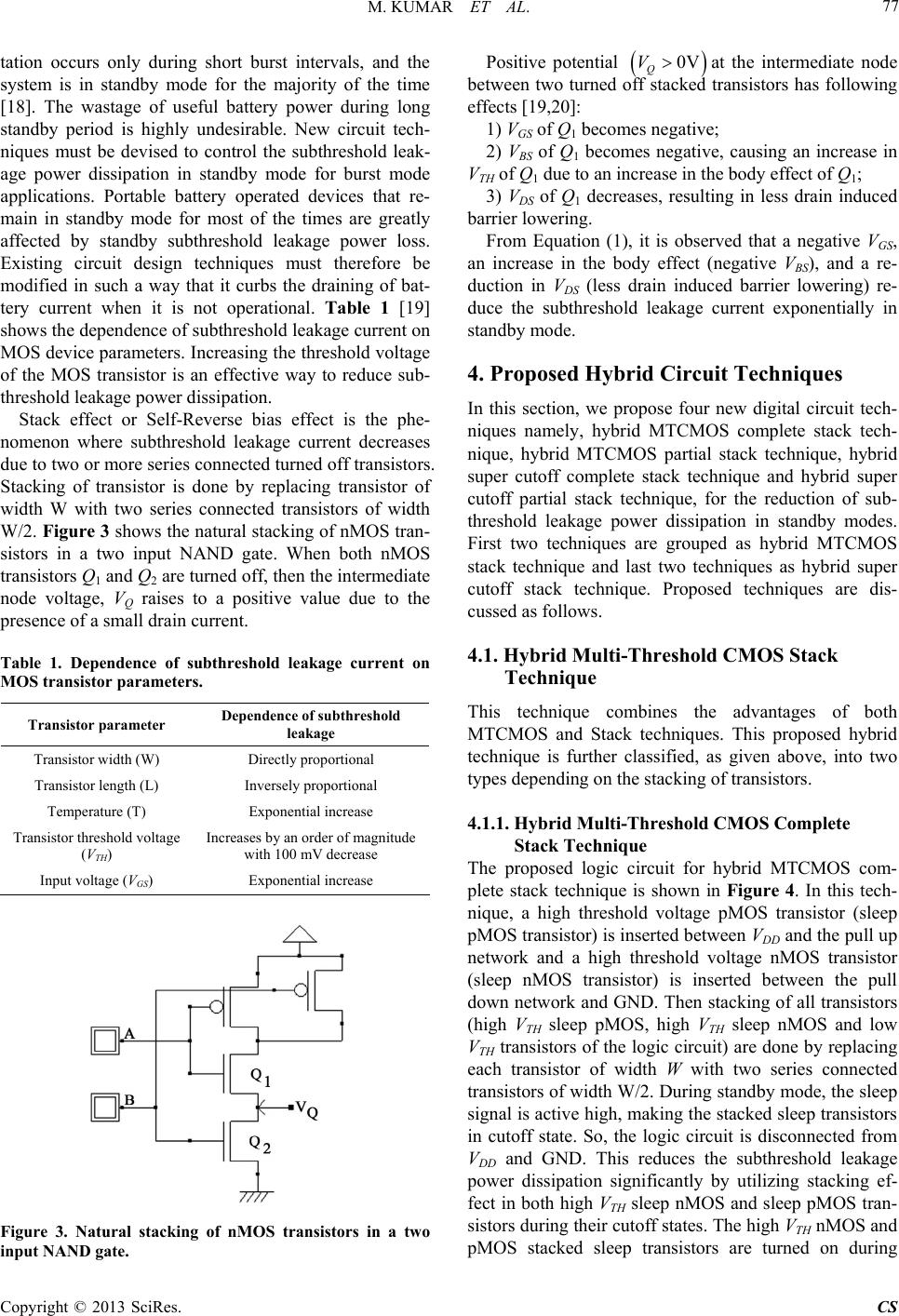 M. KUMAR ET AL. 77 tation occurs only during short burst intervals, and the system is in standby mode for the majority of the time [18]. The wastage of useful battery power during long standby period is highly undesirable. New circuit tech- niques must be devised to control the subthreshold leak- age power dissipation in standby mode for burst mode applications. Portable battery operated devices that re- main in standby mode for most of the times are greatly affected by standby subthreshold leakage power loss. Existing circuit design techniques must therefore be modified in such a way that it curbs the draining of bat- tery current when it is not operational. Table 1 [19] shows the dependence of subthreshold leakage current on MOS device parameters. Increasing the threshold voltage of the MOS transistor is an effective way to reduce sub- threshold leakage power dissipation. Stack effect or Self-Reverse bias effect is the phe- nomenon where subthreshold leakage current decreases due to two or more series connected turned off transistors. Stacking of transistor is done by replacing transistor of width W with two series connected transistors of width W/2. Figure 3 shows the natural stacking of nMOS tran- sistors in a two input NAND gate. When both nMOS transistors Q1 and Q2 are turned off, then the intermediate node voltage, VQ raises to a positive value due to the presence of a small drain current. Table 1. Dependence of subthreshold leakage current on MOS transistor parameters. Transistor parameter Dependence of subthreshold leakage Transistor width (W) Directly proportional Transistor length (L) Inversely proportional Temperature (T) Exponential increase Transistor threshold voltage (VTH) Increases by an order of magnitude with 100 mV decrease Input voltage (VGS) Exponential increase Figure 3. Natural stacking of nMOS transistors in a two input NAND gate. Positive potential 0VV Qat the intermediate node between two turned off stacked transistors has following effects [19,20]: 1) VGS of Q1 becomes negative; 2) VBS of Q1 becomes negative, causing an increase in VTH of Q1 due to an increase in the body effect of Q1; 3) VDS of Q1 decreases, resulting in less drain induced barrier lowering. From Equation (1), it is observed that a negative VGS, an increase in the body effect (negative VBS), and a re- duction in VDS (less drain induced barrier lowering) re- duce the subthreshold leakage current exponentially in standby mode. 4. Proposed Hybrid Circuit Techniques In this section, we propose four new digital circuit tech- niques namely, hybrid MTCMOS complete stack tech- nique, hybrid MTCMOS partial stack technique, hybrid super cutoff complete stack technique and hybrid super cutoff partial stack technique, for the reduction of sub- threshold leakage power dissipation in standby modes. First two techniques are grouped as hybrid MTCMOS stack technique and last two techniques as hybrid super cutoff stack technique. Proposed techniques are dis- cussed as follows. 4.1. Hybrid Multi-Threshold CMOS Stack Technique This technique combines the advantages of both MTCMOS and Stack techniques. This proposed hybrid technique is further classified, as given above, into two types depending on the stacking of transistors. 4.1.1. Hybrid Multi-Threshold CMOS Complete Stack Technique The proposed logic circuit for hybrid MTCMOS com- plete stack technique is shown in Figure 4. In this tech- nique, a high threshold voltage pMOS transistor (sleep pMOS transistor) is inserted between VDD and the pull up network and a high threshold voltage nMOS transistor (sleep nMOS transistor) is inserted between the pull down network and GND. Then stacking of all transistors (high VTH sleep pMOS, high VTH sleep nMOS and low VTH transistors of the logic circuit) are done by replacing each transistor of width W with two series connected transistors of width W/2. During standby mode, the sleep signal is active high, making the stacked sleep transistors in cutoff state. So, the logic circuit is disconnected from VDD and GND. This reduces the subthreshold leakage power dissipation significantly by utilizing stacking ef- fect in both high VTH sleep nMOS and sleep pMOS tran- sistors during their cutoff states. The high VTH nMOS and pMOS stacked sleep transistors are turned on during Copyright © 2013 SciRes. CS 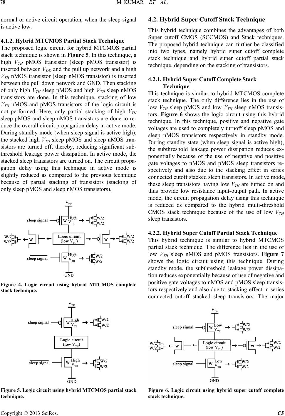 M. KUMAR ET AL. 78 normal or active circuit operation, when the sleep signal is active low. 4.1.2. Hybrid MTCMOS Partial Stack Technique The proposed logic circuit for hybrid MTCMOS partial stack technique is shown in Figure 5. In this technique, a high VTH pMOS transistor (sleep pMOS transistor) is inserted between VDD and the pull up network and a high VTH nMOS transistor (sleep nMOS transistor) is inserted between the pull down network and GND. Then stacking of only high VTH sleep pMOS and high VTH sleep nMOS transistors are done. In this technique, stacking of low VTH nMOS and pMOS transistors of the logic circuit is not performed. Here, only partial stacking of high VTH sleep pMOS and sleep nMOS transistors are done to re- duce the overall circuit propagation delay in active mode. During standby mode (when sleep signal is active high), the stacked high VTH sleep pMOS and sleep nMOS tran- sistors are turned off, thereby, reducing significant sub- threshold leakage power dissipation. In active mode, the stacked sleep transistors are turned on. The circuit propa- gation delay using this technique in active mode is slightly reduced as compared to the previous technique because of partial stacking of transistors (stacking of only sleep pMOS and sleep nMOS transistors). Figure 4. Logic circuit using hybrid MTCMOS complete stack technique. Figure 5. Logic circuit using hybrid MTCMOS partial stack technique. 4.2. Hybrid Super Cutoff Stack Technique This hybrid technique combines the advantages of both Super cutoff CMOS (SCCMOS) and Stack techniques. The proposed hybrid technique can further be classified into two types, namely hybrid super cutoff complete stack technique and hybrid super cutoff partial stack technique, depending on the stacking of transistors. 4.2.1. Hybrid Super Cutof f Complete Stack Technique This technique is similar to hybrid MTCMOS complete stack technique. The only difference lies in the use of low VTH sleep pMOS and low VTH sleep nMOS transis- tors. Figure 6 shows the logic circuit using this hybrid technique. In this technique, positive and negative gate voltages are used to completely turnoff sleep pMOS and sleep nMOS transistors respectively in standby mode. During standby state (when sleep signal is active high), the subthreshold leakage power dissipation reduces ex- ponentially because of the use of negative and positive gate voltages to nMOS and pMOS sleep transistors re- spectively and also due to the stacking effect in series connected cutoff stacked sleep transistors. In active mode, these sleep transistors having low VTH are turned on and thus provide low resistance input-output path. In active mode, the circuit propagation delay using this technique is reduced as compared to the hybrid multi-threshold CMOS stack technique because of the use of low VTH sleep transistors. 4.2.2. Hybrid Super Cutof f Partial Stack Technique This hybrid technique is similar to hybrid MTCMOS partial stack technique. The difference lies in the use of low VTH sleep nMOS and pMOS transistors. Figure 7 shows the logic circuit using this technique. During standby mode, the subthreshold leakage power dissipa- tion reduces exponentially because of use of negative and positive gate voltages to nMOS and pMOS sleep transis- tors respectively and also due to stacking effect in series connected cutoff stacked sleep transistors. The major Figure 6. Logic circuit using hybrid super cutoff complete stack technique. Copyright © 2013 SciRes. CS 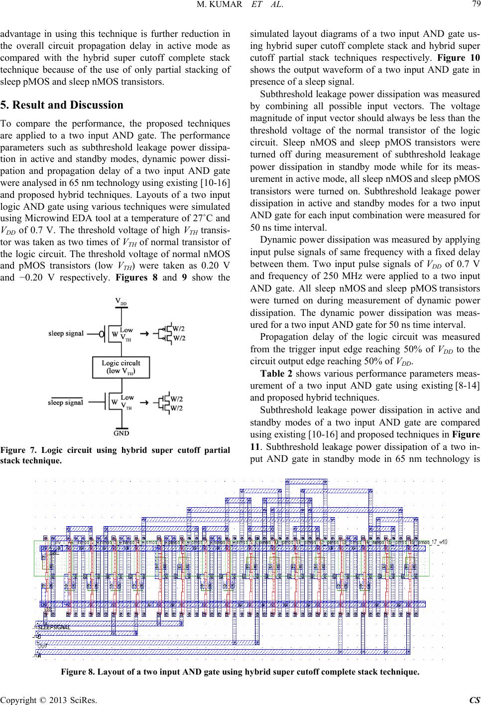 M. KUMAR ET AL. Copyright © 2013 SciRes. CS 79 advantage in using this technique is further reduction in the overall circuit propagation delay in active mode as compared with the hybrid super cutoff complete stack technique because of the use of only partial stacking of sleep pMOS and sleep nMOS transistors. simulated layout diagrams of a two input AND gate us- ing hybrid super cutoff complete stack and hybrid super cutoff partial stack techniques respectively. Figure 10 shows the output waveform of a two input AND gate in presence of a sleep signal. Subthreshold leakage power dissipation was measured by combining all possible input vectors. The voltage magnitude of input vector should always be less than the threshold voltage of the normal transistor of the logic circuit. Sleep nMOS and sleep pMOS transistors were turned off during measurement of subthreshold leakage power dissipation in standby mode while for its meas- urement in active mode, all sleep nMOS and sleep pMOS transistors were turned on. Subthreshold leakage power dissipation in active and standby modes for a two input AND gate for each input combination were measured for 50 ns time interval. 5. Result and Discussion To compare the performance, the proposed techniques are applied to a two input AND gate. The performance parameters such as subthreshold leakage power dissipa- tion in active and standby modes, dynamic power dissi- pation and propagation delay of a two input AND gate were analysed in 65 nm technology using existing [10-16] and proposed hybrid techniques. Layouts of a two input logic AND gate using various techniques were simulated using Microwind EDA tool at a temperature of 27˚C and VDD of 0.7 V. The threshold voltage of high VTH transis- tor was taken as two times of VTH of normal transistor of the logic circuit. The threshold voltage of normal nMOS and pMOS transistors (low VTH) were taken as 0.20 V and −0.20 V respectively. Figures 8 and 9 show the Dynamic power dissipation was measured by applying input pulse signals of same frequency with a fixed delay between them. Two input pulse signals of VDD of 0.7 V and frequency of 250 MHz were applied to a two input AND gate. All sleep nMOS and sleep pMOS transistors were turned on during measurement of dynamic power dissipation. The dynamic power dissipation was meas- ured for a two input AND gate for 50 ns time interval. Propagation delay of the logic circuit was measured from the trigger input edge reaching 50% of VDD to the circuit output edge reaching 50% of VDD. Table 2 shows various performance parameters meas- urement of a two input AND gate using existing [8-14] and proposed hybrid techniques. Subthreshold leakage power dissipation in active and standby modes of a two input AND gate are compared using existing [10-16] and proposed techniques in Figure 11. Subthreshold leakage power dissipation of a two in- put AND gate in standby mode in 65 nm technology is Figure 7. Logic circuit using hybrid super cutoff partial stack technique. Figure 8. Layout of a two input AND gate using hybr id supe r cutoff complete stack technique . 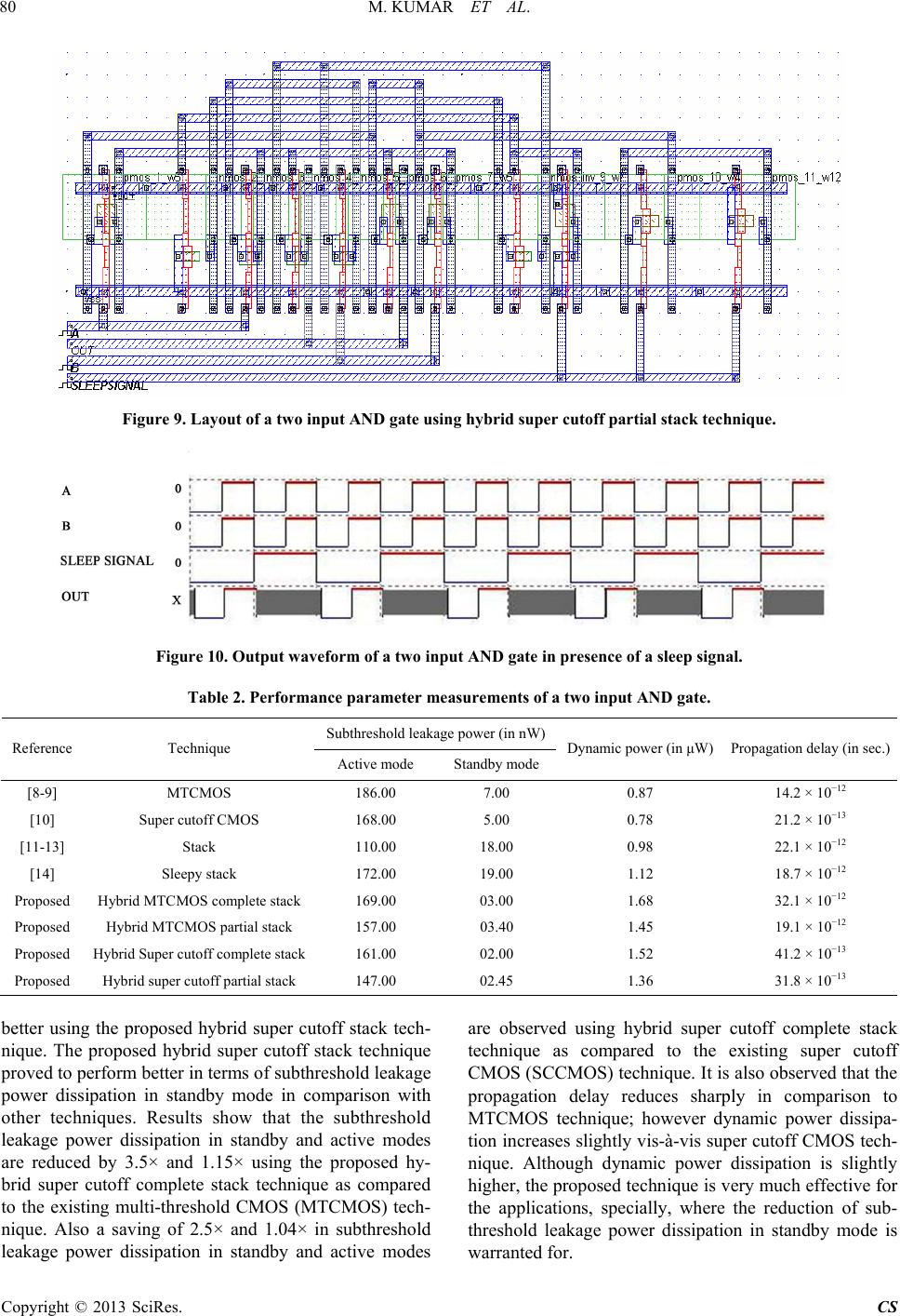 M. KUMAR ET AL. 80 Figure 9. Layout of a two input AND gate using hybrid super cutoff par t ial stac k te chnique. Figure 10. Output waveform of a two input AND gate in presence of a sleep signal. Table 2. Performance parameter measure ments of a two input AND gate. Subthreshold leakage power (in nW) Reference Technique Active mode Standby mode Dynamic power (in μW) Propagation delay (in sec.) [8-9] MTCMOS 186.00 7.00 0.87 14.2 × 10⁻¹² [10] Super cutoff CMOS 168.00 5.00 0.78 21.2 × 10⁻¹³ [11-13] Stack 110.00 18.00 0.98 22.1 × 10⁻¹² [14] Sleepy stack 172.00 19.00 1.12 18.7 × 10⁻¹² Proposed Hybrid MTCMOS complete stack 169.00 03.00 1.68 32.1 × 10⁻¹² Proposed Hybrid MTCMOS partial stack 157.00 03.40 1.45 19.1 × 10⁻¹² Proposed Hybrid Super cutoff complete stack 161.00 02.00 1.52 41.2 × 10⁻¹³ Proposed Hybrid super cutoff partial stack 147.00 02.45 1.36 31.8 × 10⁻¹³ better using the proposed hybrid super cutoff stack tech- nique. The proposed hybrid super cutoff stack technique proved to perform better in terms of subthreshold leakage power dissipation in standby mode in comparison with other techniques. Results show that the subthreshold leakage power dissipation in standby and active modes are reduced by 3.5× and 1.15× using the proposed hy- brid super cutoff complete stack technique as compared to the existing multi-threshold CMOS (MTCMOS) tech- nique. Also a saving of 2.5× and 1.04× in subthreshold leakage power dissipation in standby and active modes are observed using hybrid super cutoff complete stack technique as compared to the existing super cutoff CMOS (SCCMOS) technique. It is also observed that the propagation delay reduces sharply in comparison to MTCMOS technique; however dynamic power dissipa- tion increases slightly vis-à-vis super cutoff CMOS tech- nique. Although dynamic power dissipation is slightly higher, the proposed technique is very much effective for the applications, specially, where the reduction of sub- threshold leakage power dissipation in standby mode is warranted for. Copyright © 2013 SciRes. CS 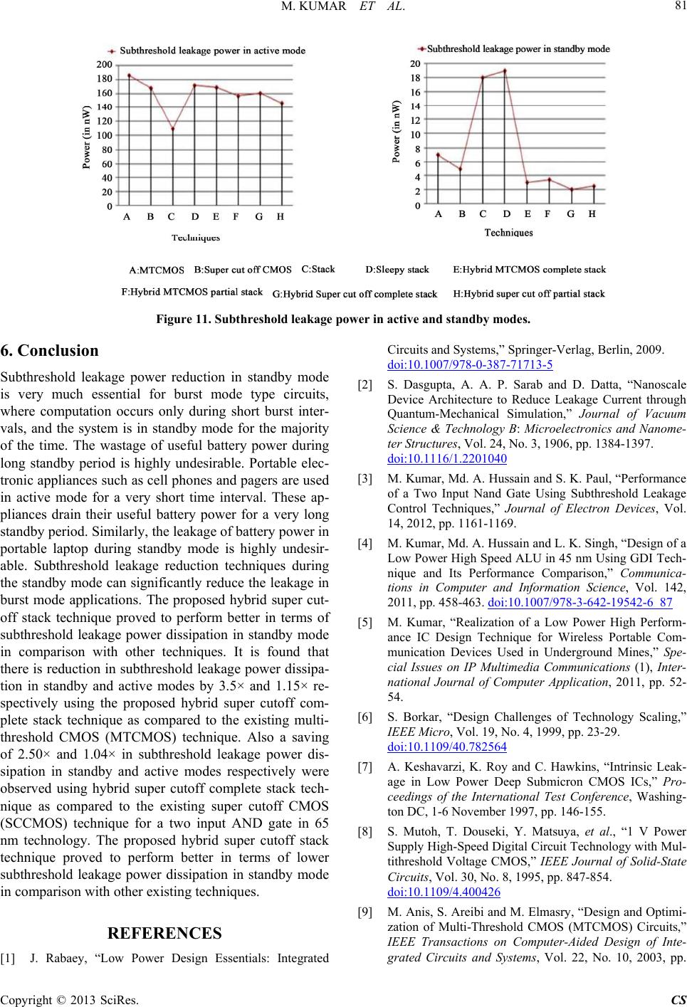 M. KUMAR ET AL. 81 Figure 11. Subthre shold le akage power in active and standby modes. 6. Conclusion Subthreshold leakage power reduction in standby mode is very much essential for burst mode type circuits, where computation occurs only during short burst inter- vals, and the system is in standby mode for the majority of the time. The wastage of useful battery power during long standby period is highly undesirable. Portable elec- tronic appliances such as cell phones and pagers are used in active mode for a very short time interval. These ap- pliances drain their useful battery power for a very long standby period. Similarly, the leakage of battery power in portable laptop during standby mode is highly undesir- able. Subthreshold leakage reduction techniques during the standby mode can significantly reduce the leakage in burst mode applications. The proposed hybrid super cut- off stack technique proved to perform better in terms of subthreshold leakage power dissipation in standby mode in comparison with other techniques. It is found that there is reduction in subthreshold leakage power dissipa- tion in standby and active modes by 3.5× and 1.15× re- spectively using the proposed hybrid super cutoff com- plete stack technique as compared to the existing multi- threshold CMOS (MTCMOS) technique. Also a saving of 2.50× and 1.04× in subthreshold leakage power dis- sipation in standby and active modes respectively were observed using hybrid super cutoff complete stack tech- nique as compared to the existing super cutoff CMOS (SCCMOS) technique for a two input AND gate in 65 nm technology. The proposed hybrid super cutoff stack technique proved to perform better in terms of lower subthreshold leakage power dissipation in standby mode in comparison with other existing techniques. REFERENCES [1] J. Rabaey, “Low Power Design Essentials: Integrated Circuits and Systems,” Springer-Verlag, Berlin, 2009. doi:10.1007/978-0-387-71713-5 [2] S. Dasgupta, A. A. P. Sarab and D. Datta, “Nanoscale Device Architecture to Reduce Leakage Current through Quantum-Mechanical Simulation,” Journal of Vacuum Science & Technology B: Microelectronics and Nanome- ter Structures, Vol. 24, No. 3, 1906, pp. 1384-1397. doi:10.1116/1.2201040 [3] M. Kumar, Md. A. Hussain and S. K. Paul, “Performance of a Two Input Nand Gate Using Subthreshold Leakage Control Techniques,” Journal of Electron Devices, Vol. 14, 2012, pp. 1161-1169. [4] M. Kumar, Md. A. Hussain and L. K. Singh, “Design of a Low Power High Speed ALU in 45 nm Using GDI Tech- nique and Its Performance Comparison,” Communica- tions in Computer and Information Science, Vol. 142, 2011, pp. 458-463. doi:10.1007/978-3-642-19542-6_87 [5] M. Kumar, “Realization of a Low Power High Perform- ance IC Design Technique for Wireless Portable Com- munication Devices Used in Underground Mines,” Spe- cial Issues on IP Multimedia Communications (1), Inter- national Journal of Computer Application, 2011, pp. 52- 54. [6] S. Borkar, “Design Challenges of Technology Scaling,” IEEE Micro, Vol. 19, No. 4, 1999, pp. 23-29. doi:10.1109/40.782564 [7] A. Keshavarzi, K. Roy and C. Hawkins, “Intrinsic Leak- age in Low Power Deep Submicron CMOS ICs,” Pro- ceedings of the International Test Conference, Washing- ton DC, 1-6 November 1997, pp. 146-155. [8] S. Mutoh, T. Douseki, Y. Matsuya, et al., “1 V Power Supply High-Speed Digital Circuit Technology with Mul- tithreshold Voltage CMOS,” IEEE Journal of Solid-State Circuits, Vol. 30, No. 8, 1995, pp. 847-854. doi:10.1109/4.400426 [9] M. Anis, S. Areibi and M. Elmasry, “Design and Optimi- zation of Multi-Threshold CMOS (MTCMOS) Circuits,” IEEE Transactions on Computer-Aided Design of Inte- grated Circuits and Systems, Vol. 22, No. 10, 2003, pp. Copyright © 2013 SciRes. CS 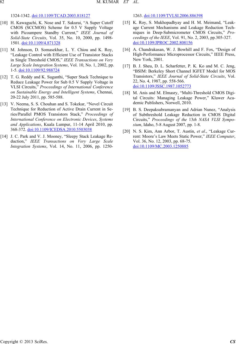 M. KUMAR ET AL. 82 1324-1342. doi:10.1109/TCAD.2003.818127 [10] H. Kawaguchi, K. Nose and T. Sakurai, “A Super Cutoff CMOS (SCCMOS) Scheme for 0.5 V Supply Voltage with Picoampere Standby Current,” IEEE Journal of Solid-State Circuits, Vol. 35, No. 10, 2000, pp. 1498- 1501. doi:10.1109/4.871328 [11] M. Johnson, D. Somasekhar, L. Y. Chiou and K. Roy, “Leakage Control with Efficient Use of Transistor Stacks in Single Threshold CMOS,” IEEE Transactions on Very Large Scale Integration Systems, Vol. 10, No. 1, 2002, pp. 1-5. doi:10.1109/92.988724 [12] T. G. Reddy and K. Suganthi, “Super Stack Technique to Reduce Leakage Power for Sub 0.5 V Supply Voltage in VLSI Circuits,” Proceedings of International Conference on Sustainable Energy and Intelligent Systems, Chennai, 20-22 July 2011, pp. 585-588. [13] V. Neema, S. S. Chouhan and S. Tokekar, “Novel Circuit Technique for Reduction of Active Drain Current in Se- ries/Parallel PMOS Transistors Stack,” Proceedings of International Conference on Electronic Devices, Systems and Applications, Kuala Lumpur, 11-14 April 2010, pp. 368-372. doi:10.1109/ICEDSA.2010.5503038 [14] J. C. Park and V. J. Mooney, “Sleepy Stack Leakage Re- duction,” IEEE Transactions on Very Large Scale Integration Systems, Vol. 14, No. 11, 2006, pp. 1250- 1263. doi:10.1109/TVLSI.2006.886398 [15] K. Roy, S. Mukhopadhyay and H. M. Meimand, “Leak- age Current Mechanisms and Leakage Reduction Tech- niques in Deep-Submicrometer CMOS Circuits,” Pro- ceedings of the IEEE, Vol. 91, No. 2, 2003, pp.305-327. doi:10.1109/JPROC.2002.808156 [16] A. Chandrakasan, W. J. Bowhill and F. Fox, “Design of High-Performance Microprocessor Circuits,” IEEE Press, New York, 2001. [17] B. J. Sheu, D. L. Scharfetter, P. K. Ko and M. C. Jeng, “BSIM: Berkeley Short Channel IGFET Model for MOS Transistors,” IEEE Journal of Solid-State Circuits, Vol. 22, No. 4, 1987, pp. 558-566. doi:10.1109/JSSC.1987.1052773 [18] M. Anis and M. Elmasry, “Multi-Threshold CMOS Digi- tal Circuits: Managing Leakage Power,” Kluwer Aca- demic Publishers, Norwell, 2010. [19] B. S. Deepaksubramanyan and Adrian Nunez, “Analysis of Subthreshold Leakage Reduction in CMOS Digital Circuits,” Proceedings of the 13th NASA VLSI Sympo- sium, Idaho, 5-8 August 2007, pp. 1-8. [20] N. S. Kim, Ann Arbor, T. Austin, et al., “Leakage Cur- rent: Moore’s Law Meets Static Power,” IEEE Computer, Vol. 36, No. 12, 2003, pp. 68-75. doi:10.1109/MC.2003.1250885 Copyright © 2013 SciRes. CS
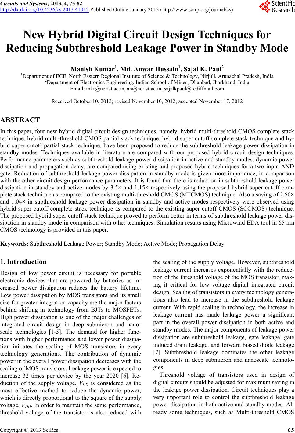
|