Paper Menu >>
Journal Menu >>
 Journal of Water Resource and Protection, 2013, 5, 97-110 http://dx.doi.org/10.4236/jwarp.2013.51012 Published Online January 2013 (http://www.scirp.org/journal/jwarp) Prediction of Flow Duration Curves for Ungauged Basins with Quasi-Newton Method Mutlu Yaşar*, Neset Orhan Baykan Department of Civil Engineering, Pamukkale University, Denizli, Turkey Email: *mutluyasar@pau.edu.tr Received November 5, 2012; revised December 6, 2012; accepted December 14, 2012 ABSTRACT Prediction of flow-duration-curves (FDC) is an important task for water resources planning, management and hydraulic energy production. Classification of the basins as carstic and non-carstic may be used to estimate parameters of the FDC with predictive tools for catchments with/without observed stream flow. There is a need for obtaining FDC for un- gauged stations for efficient water resource planning. Thus, study proposes a quite new approach, called the EREFDC model, for estimating the parameters of the FDC for which the parameters of the FDC are obtained with quasi-Newton method. Estimation are made for using the bv gauged stations at first than the FDC parameters are estimated for un- gauged stations based on drainage area, annual mean precipitation, mean permeability, mean slope, latitude, longitude, and elevation from the mean sea level are used. The EREFDC model consists of various type of linear- and nonlinear mathematical equations, is able to predict a wide range of the FDC parameters for gauged and ungauged basins. The method is applied to 72 unimpaired catchments studied are about for 50 years average daily measured stream flow. Re- sults showed that the EREFDC model may be used for estimating. FDC parameters for ungauged hydrological basins in order to find FDC for ungauged stations. Results also showed that the EREFDC model performs better in carstic regions than non-carstic regions. In addition, parameters of FDC for tributaries at the basins with insufficient flow data or without flow data may be determined by using basin characteristics. Keywords: Flow Duration Curve; Optimization; BFGS Algorithm; Basin Characteristics 1. Introduction Efficient use of energy sources is a major problem all over the world, especially renewable energy that is a core prerequisite for sustainable development. Hydroelectric energy is one of the sustainable energy sources that need to be carefully planned for future generations. Moreover, technological developments require gradually increasing energy needs in the future, but, it is usually not equally distributed in place and time in the world. Modeling a flow duration curve (FDC) is essential for the power plants where the measurement could not be performed and the plants are run-of-the river type. This is one of the main the reason why hydrologists give so much importance to this subject. In addition, prediction of FDCs in ungauged stations are still challenging pro- blem for hydrological community. One way of efficient planning and use of hydroelectric energy require good measured data for all stream flows around the hydrological basins. This is usually impossible since it requires considerable amount of money and for gauging all the basins. Thus it needs to be method that deals with the parameter estimation of flow-duration- curves (FDC) for gauged and ungauged basins. The FDC is a parametric methods that supplies the necessary in- formation for the various water resource applications [1]. The values of daily FDCs present the most valuable in- formation for the regional regime of flow during hydroe- lectric power station application in a streambed [2]. In addition, a stream flow system can be defined by a FDC showing the distribution of flow frequencies obtained from measured flows. If the data are unattainable or lim- ited, plenty of sources should be evaluated. Therefore, for the places where measurements cannot be carried out estimation of FDCs is needed. An experimental FDC can be easily obtained from flow observations by using stan- dard nonparametric processes. The regionalization of a FDC is important when working with basins without gauging stations and shortage of flow data. The usefulness of FDC is that it is a main input for Hydroelectric Power Plants (HEPP) that is classified into two main groups: 1) The HEPP with stored, regulated, and directly diverted of natural flows; and 2) The HEPP with storage reservoirs for which the flows have random characters in time and they are regulated by means of *Corresponding author. C opyright © 2013 SciRes. JWARP  M. YAŞAR, N. O. BAYKAN 98 storing so that reliable and firm energy may be obtained by using this regulated amount of water. In the case of nonstored HEPP’s, energy is to be produced in the pow- erhouse changes as a function of the existing flow value in the river bed if there is no storage area due to the to- pography. Therefore, this type of HEPP requires real- estimation of flow quantity for relevant design and effi- cient use of stream flow. Long term hydrologic data are generally not available in many hydrological basins. Annual mean flow values are commonly considered in many hydrologic design- studies. In order to obtain daily flow data at projected- point, an index-station of long-term observation values is selected considering similar geographical conditions. If the annual flow data are persistent and representative for the region, the data transfer is assumed to be done prop- erly. It is known that the FDC are synthetic (artificial) curves so that the occurrences of the flows are disturbed by putting the flows to descending or ascending order. FDC is not a cumulative probability curve because the time series of the flows in a stream are not stationery for the intervals less than a year, so that the statistical char- acteristics change along the year like mean, standard de- viation, and coefficient of skewness. Therefore, the ex- ceedence probability of the flow in a certain day depends on the day where it is placed in [3]. If a generalized FDC is drawn for each stream basin with observed data, the FDC with a certain errata may be obtained for the basins of nongauged stations. Fennessey and Vogel [4] developed flow duration cur- ves for the regions without adjustment and gauging sta- tion in Massachusetts and they analyzed the new models related with the regional flow duration curves. FDCs they found that have a complex structure requiring probability density functions with frequently three or more parame- ters. They approximated daily FDCs by utilizing two- parameter lognormal probability density function. Mimi- kou and Kaemaki [5] regionalized the flow duration curve by using the morpho-climatological properties of the drainage basin. They explained the regional variabil- ity of the flow duration curve associated with every pa- rameter with the help of multiple regression techniques by using annual mean regional precipitation, basin area, hypsometric head and stream length. Alkan [6] suggested the dimensionless FDC uses from in Equation (1). et Q (1) where, then, Q is the flow (m3/sec), t is the time series, α and β are the parameters of the FDC. Alkan [6] found that there is a nonlinear dependence between the natural logarithm of the initial value of the exponential model parameters and natural logarithm of coefficient of annual flows. This parametric model has been employed to the stream gauging stations in carstic and non-carstic basins in Turkey. Singh et al. [7] made modeling of the FDCs for the small water projects without gauging stations and the basins with insufficient measurements in the Hima- layas. Dimensionless FDCs were obtained by using nor- mal, lognormal and exponential conversions from basins with gauging stations to the basins without gauging sta- tions. Yu and Yang [8] obtained FDCs for Cho-Shuei Creek in Taiwan and they tested the validity of the FDCs. They determined that polynomial method contains less uncertainty compared to area index method according to the analyses of uncertainty of obtained FDCs. The studies on the deficiencies of flow measurements are carried out by many researchers in many places in the world such as Greece [5], the USA [4], Italy [9], India [7], Taiwan [10] and Portugal [11]. Crocker et al. [11] aimed to obtain a regional model in order to estimate the FDC for basins without measurements in some parts of Portugal. They used cumulative distribution function to combine a model used in estimation of a FDC when flow is not zero and a model used in estimation of the period, in percentage, when there is no stream [11]. Cole et al. [12] indicated that the users of flow data need independ- ent qualification indicator in order to use the data safely and they suggested the use of long term FDCs as an in- dicator. This method lights the way visually for the dis- order in flow data and gives the place and the form of the fault. Krasovskaia et al. [13] developed a model to estimate a FDC for the basins without gauging stations. FDCs were obtained experimentally by using a medium value and a distribution coefficient and then, they were made definable as regional FDCs or theoretical regional curves. Development of first degree moments of FDCs along a river system and their local scale like a basin area were analyzed as well as interpolations along the river system were prepared carefully. Daily flow data of Costa Rica were used in the study. Estimation errors are relatively about 30% higher for a period longer than 85%. However, for a period lower than 20% and in the center of a FDC, they become smaller about 10% and 8%, respectively. The differences between experimental and theoretical FDCs are low and better results were obtained in the center parts of a FDC. Bari and Islam [14] applied a stochastic approach in order to obtain a FDC associated with a one year period and get rid of difficulties of a traditional FDC in which the date order of flows are masked. They investigated the theoretical development of a stochastic FDC and prob- ability distribution suitable to the average daily flow dis- tribution. The model was applied to the chosen four streams of Bangladesh. Small catchment areas are very important for the development of local water resources. As long as the global pressure on water resources in- creases, the potential of the drainage areas will continue to increase. Generally, the highland catchment areas with Copyright © 2013 SciRes. JWARP  M. YAŞAR, N. O. BAYKAN 99 important water resources are suitable for the develop- ment of small hydroelectric energies. Estimation of a FDC is important for the design of hydraulic structures and related environmental assessment. Niadas [15] suggested an approach about development of symbolic daily FDCs for small catchment areas by combining regional data with real instant flow data. An- nual mean flow values were estimated by using instant flow data of the two regions in representation of the flow regime statistically. Castellarin et al. [16] showed the relation between the frequency and dimension of the overflow in a FDC. Their study also aimed to estimate the FDC of streams without flow values by evaluating the efficiency and correctness of the data. The study was carried out for a large area in east Italy. In order to evaluate the uncertainty of the re- gional FDCs, they accepted the jack-knife cross valida- tion method. Results included: a) The evaluation of reli- ability of regional FDCs for imponderable areas; b) the closeness of reliability data for the best three regional models presented; and c) The empirical FDC’s based on limited data samples generally provide a better fit of the long-term FDC’s than regional FDC’s. Ming et al. [17] proposed an index model for pre- dicting the FDCs. The proposed index model was defined as nonparametric relationship between each parameter to the predictive tools and a linear combination of predic- tors. They found that the index model improved the pre- diction performance for ungauged stations. Similar study was due to Ganora et al. [18], where distance-based model was used to predict FDC for ungauged stations. They found that the distance-based model produced better es- timates of the flow duration curves using only few catch- ment descriptors. Yokoo and Sivapalan [19] proposed an FDC curve reconstruction with climatic and landscape controls. Similar study was carried out by Viola et al. [20] for which the regional FDC was obtained in Sicily. The regional regression estimates were proposed in that study. In all approaches involving the regionalization of FDCs, the applicability of the estimation methods for the small catchment areas for ungauged stations is quite limited. In addition, use of regression techniques developed so far for the regional estimations may not best represent the basin characteristics. Therefore, accurate estimations for small catchment areas need to be made with proper mathematical equations with commonly obtainable data for the region such as drainage area, mean precipitation rate, etc. Moreover there are many studies on the predic- tion of FDC curve with linear regression techniques and the statistical methods, but there is limited study on esti- mation of the FDC with nonlinear equations with re- gional parameters. One way of estimating the FDC pa- rameters may be use of numerical method such as quasi- Newton method. The most popular quasi-Newton algo- rithm is the BFGS method, named by its discoverers Broyden, Fletcher, Goldfarb, and Shanno. The BFGS method is derived from the Newton’s method in optimi- zation, a class of hill-climbing optimization techniques that seeks the stationary point of a function, where the gradient is zero. Newton’s method assumes that the func- tion can be locally approximated as a quadratic Taylor expansion in the region around the optimum, and uses the first and second derivatives to find the stationary point. Many nonlinear equations for FDC parameter es- timation are solved with the BFGS algorithm using the tools in Excel solver [21]. The α and β parameters given in Equation (1) of the FDC are subsequently solved with solver tool in Excel by minimizing observed and esti- mated values of stream flow by using drainage area, an- nual mean precipitation, mean permeability, mean slope, latitude, longitude, and elevation from the mean sea level. During the estimation, the α and β parameters are ob- tained by an parametric Equation given in (1) at first for each gauged stations, then by using regional parameters (such as drainage are, mean slope, etc.) as an independ- ent variable, α and β parameters are regionalized with set of linear and nonlinear equations given in Section 2. The data need for estimating the parameters of FDC curves are obtained from US Geological Survey (USGS). The detailed information about the method [22] carried out in the USA applications in which the data transfer is performed for the imponderable area with the correlation between concurrent flows can be attained from USGS articles and reports [23,24]. The rest of the paper is organized as follows: The next section is about model development. Section 3 is about BFGS algorithm. Section 4 is on data collection and evaluation and finally, conclusions are given in Section 5. 2. Model Development Modeling procedure is carried out in two steps: Step I: Obtaining parameters for each gauging sta- tions The parameters of FDC for each of the gauged stations are obtained in Equation (1). In order to obtain the α and β parameters, in Equation (1) the average daily flows data are used for each stations that is averaged over 60 years of measured daily flow. Average daily flow for one-year long period are put into an order from maxi- mum to minimum as referenced to a beginning of the January first for that year. Typical FDC curve are given in Figure 1 for station 1, named Pawnee R. at Rozel, in Kansas. As can be seen in Figure 1, the fitted FDC and measured FDC cure are in good agreement with the theoretical FDC. Estimating the parameters of α and β are obtained first for each of the stations, and then the regionalization is made at Step II. Copyright © 2013 SciRes. JWARP  M. YAŞAR, N. O. BAYKAN 100 Figure 1. Typical FDC curve of Pawnee R. at Rozel, in Kansas. At Step I, the α and β parameters are calculated for each gauging stations by minimizing Equation (2) as: 1 Min T est t SSEQ Q 8 (2) where SS E is the sum of squared errors between ob- served stream flows, Q, estimated stream flow Qest, and T is the total number of daily observed stream flow. That is set as T = 365. During solution quasi-Newton method with solver toolbox are used. Step II. Regionalization By using the α and β parameters obtained. at Step I, the regionalization is carried out at Step II by using the regional parameters as drainage area (DA), annual mean precipitation (AMP), mean permeability (MP), mean slope (MS), latitude (LAT), longitude (LONG), and elevation from the mean sea level (EL). Equations are given in Equations (3) and (4). 26 4 1 10 12 14 0132 53 74 95 116 137 **** *** x xx xxx x (3) 26 4 1 10 12 14 0132 53 74 95 116 137 **** *** 8 x xx xxx x (4) x1 = Drainage area (km2); x2 = Annual mean precipitation (mm); x3 = Mean permeability (mm/h); x4 = Mean slope (%); x5 = Latitude(˚); x6= Longitude(˚); x7 = Elevation (mm). where, ω are the weighting coefficient of the nonlinear equations. It is quite difficult for field engineers to use the FDC directly given in Equations (3) and (4) since most of them may not have the optimization knowledge; Thus, the α and β parameters are obtained by quasi- Newton method so called BFGS given in Section 3. Be- fore applying Equations (3) and (4), the hydrological basins are clustered into two groups as carstic and non- carstic. The reason for clustering is a discharge differ- ence between carstic and non-carstic regions in terms of drainage and flow characteristics. Equations (3) and (4) are used to solve Equations (5) and (6) during solution process, the following objective functions are used: 1 min I p re i SSE (5) 1 min I p re i SSE (6) where, I is the total number of gauged stations for each carstic and non-carstic groups, α and β are the FDC pa- rameters obtained from Step I, αpre and βpre are the pre- dicted values. Flowchart of the proposed Estimation of REgionalized Flow Duration Curve (EREFDC) is given in Figure 2. As can be seen in Figure 2, the EREFDC model starts with obtaining the parameters of FDC firs and then by using the regional geographical and hydrological para- meters, the parameters of the EREFDC are obtained us- ing the quasi-Newton method as given in Figure 2. 3. BFGS Algorithm The most popular quasi-Newton algorithm is the BFGS method, named by its discoverers Broyden, Fletcher, Goldfarb, and Shanno. The BFGS method is derived from the Newton’s method in optimization, a class of hill- climbing optimization techniques that seeks the station- ary point of a function, where the gradient is zero. New- ton’s method assumes that the function can be locally approximated as a quadratic Taylor expansion in the re- gion around the optimum, and uses the first and second derivatives to find the stationary point. Detailed discus- sion of BFGS method can be found in some numerical optimization textbooks, see the references [25,26]. The BFGS algorithm can be summarized as follows [26,27]: Step 1: Estimate an initial design vector Choose a symmetric positive definite matrix as an estimate for the Hessian of the cost function. In the absence of more information, let 0.X 0 H 0. HI Choose a convergence para- meter . Set 0k , and compute the gradient vector as 0 g 0 Xc . Where, k is iteration index and g is the cost function of the design vector. Step 2: Calculate the norm of the gradient vector as k c. If , k c then stop the iterative process; other- wise continue. Step 3: Solve the linear system of equations to obtain the search direction. Where, d is search direction vector. kk k Hd c Step 4: Compute optimum step size k to mini- mize kk gXd . Copyright © 2013 SciRes. JWARP  M. YAŞAR, N. O. BAYKAN Copyright © 2013 SciRes. JWARP 101 Figure 2. Flow-chart of EREFDC. Step 5: Update the design as . 1kk XXd k k aawhere the correction matrices Dnd Ere given as k k Step 6: Update the Hessian approximation for the cost function as ; TT kk kk kk kkk k yy cc DE ys cd 1kkkHHDE  M. YAŞAR, N. O. BAYKAN 102 kk k sd (change in design); k (change in gradient); Step 7: Set 4. The EREFDC Model Application 4.lection ata for 72 America. Kansas is the 15th with area of 213.089 km2. The ations used in the EREFDC modeling studies are selected from those are not affected from the rate of the rresponding physical and geographical. Station Number Station Name Drainage Area Mean Mean SlopeLatitude Longitude x6 (˚) Elevation x7 (mm) 1kk yc c 1k g c 1k X 1 and go to Step 2. kk 1. Data Col This study uses average daily stream flow d catchments in Kansas city in largest state of the USA stream flow data are for relatively unimpaired catch- ments. The catchment size ranges from 120 to 30,000 km2 and data length varies from 20 to 100 years. The avail- able data in Kansas City has been downloaded from the source: http://waterdata.usgs.gov. Elevation, mean slope permeability and precipitation are taken from Perry et al. [28]. 4.1.1. Flow Data The st flow namely uncontrolled flow. Stations and their corre- sponding data are given in Table 1. As can be seen in Table 1 drainage area varies between 10 - 3100 km2, annual precipitation varies between 100 - 1000 mm, av- erage basin permeability varies between 10 and 140 mm/h, the slope of the basin varies between 0.8% - 6.0% and the elevation value varies between 200 - 800 m. Each of station includes a data from an average daily stream flow that has a length of 366 data in a year. One example of the data are given in Appendix for station number 6814000 Turkey C. 72 station are taken into ac- count during the EREFDC model developments since there are no homogenous data on other station in the ba- sin in Kansas city, USA. Data are classified as carstic and non-carstic group by putting them into an order ac- cording to the minimum and maximum station number. 80% of the carstic and non-carstic data are used for ERECFDC model development and 20% of them are used for EREFDC model testing. Carstic map are given in Figure 3. In order to find Figure 3, each gauged stations are extracted according to their coordinates, then those coordinates matched with carst maps taken from http//:pubs.usgs.gov/of/2004/1352/. Table 1. Station numbers and their co Annual Mean x1 (km2) Precipitation x2 (mm) Perme-ability x3 (mm/h) x4 (%) x5 (˚) 6814urkey000 T C. 714.8 822 12 3.10 39.9 96.1 316.2 6815000 Big Ne. 6848500 Praire Dog 2608.1 548 35 2.10 40.0 99.5 614.5 9207.100. 1351 100.0 k Sol. 1237 . . maha R3468 827 13 2.80 40.0 95.6 261.6 6860000 Smooky Hill R.5 449 39 1.30 38.8 9 799.4 6861000 Smooky Hill 9 468 39 1.40 38.8 669.4 6863500 Big C. 1538.5 554 30 1.40 38.9 99.3 595.5 6866500 Smooky Hill R. 21647 529 37 1.60 38.7 97.6 378.0 6866900 Saline R. 1802.6 523 35 1.50 39.1 99.9 675.9 6867000 Saline R.3890.2 551 35 2.20 39.0 98.9 472.9 6869500 Saline R. 7303.8 602 33 2.50 39.0 97.9 385.7 6871000 N. Fork Sol. R.2198.9 541 34 2.50 39.7 99.3 534.6 6873000 South For2693.6 530 37 2.10 39.4 99.6 589.3 6876700 Salt C. 994.6 685 28 2.60 39.1 97.8 380.1 6878000 Chapman C. 777 785 26 2.20 39.0 97.0 336.0 6879650 Kings C. 714.00 838 12 5.90 39.1 96.6 333.6 6882000 Big Blue R.11517 725 21 1.30 40.0 96.6 354.2 6882510 Big Blue R. 2 728 21 1.40 39.8 96.7 338.4 6884000 Little Blue R6086.5 694 36 1.40 40.1 97.2 389.3 6884025 Little Blue R7127.7 702 35 1.60 40.0 97.0 370.7 6884200 Mill C. 891 778 23 2.40 39.8 97.0 384.5 Copyright © 2013 SciRes. JWARP  M. YAŞAR, N. O. BAYKAN 103 Continued 6884400 Little Blue R. 8609.2 717 33 1.70 39.7 96.8 347.5 6885500 B. Vermillion R. 1061.9 846 9 2.40 39.7 96.4 337.4 illion R. 1 ermillion C. 629.4 887 11 3.40 39.3 96.2 302.4 e R. 1 ygnes R. es R. C. s R. es R. 3 3 . R. R. h R. . g C. 6888000 Vermillion C. 629.4 887 11 3.40 39.3 96.2 302.4 6884200 Mill 6884400 C. Little Blue R. 891 8609.2 778 717 23 33 2.40 39.8 1.70 97.0 96.8 384.5 347.5 39.7 6885500 B. Verm061.9 846 9 2.40 39.7 96.4 337.4 6888000 V 6888500 Mill C. 818.4 881 13 4.20 39.1 96.2 294.1 6889200 Soldier C. 406.6 905 12 3.20 39.2 95.9 281.7 6889500 Soldier C. 751.1 908 14 3.30 39.1 95.7 263.0 6890100 Delawar116.3 914 10 3.10 39.5 95.5 280.7 6891500 Wakarusa R. 1100.8 930 16 2.60 38.9 95.3 243.6 6892000 Stranger C. 1051.5 962 13 3.20 39.1 95.0 244.1 6893080 Blue R. 119.1 999 15 2.10 38.8 94.7 270.1 6910800 M. des C458.4 909 10 2.20 38.6 96.0 319.5 6911000 M.des Cygn909.1 930 11 2.20 38.5 95.7 287.1 6911900 Dragoon C.295.3 916 11 2.70 38.7 95.8 309.7 6912500 H and T Mile 834 920 12 2.30 38.6 95.6 280.1 6913000 M. des Cygne2693.6 928 12 2.20 38.6 95.5 272.4 6913500 M. des Cygn C. 3237.5 932 13 2.20 38.6 95.3 261.4 6914650 Big Bull 380.7 997 17 2.10 38.7 94.9 260.4 6917000 Little Osage R. 764.1 103 18 2.00 38.0 94.7 235.3 7140850 Pawnee R. 242.68520 28 1.10 38.2 99.6 640.9 7141200 Pawnee R. 5563.3 533 28 1.10 38.2 99.4 621.9 7141780 Walnut C. 087.3 534 30 1.10 38.5 99.4 610.9 7141900 Walnut C. 3651.9 544 30 1.20 38.5 99.0 578.3 7142575 Rattlesnake C. 2711.7 620 150 0.70 38.1 98.5 544.1 7143300 Cow C. 1885.5 664 33 0.90 38.3 98.2 496.3 7143665 Little Arkansas R sas 1906.2 749 53 0.80 38.1 97.6 424.1 7144200 Little Arkan3436.9 771 51 0.80 37.8 97.4 404.1 7144780 N.Fork Nin.2038.3 682 139 0.70 37.9 98.0 443.8 7145200 S. Ninnesca1683.5 692 78 1.30 37.6 97.9 413.9 7145500 Ninnescah R.5514.1 713 96 1.10 37.5 97.4 372.6 7145700 Slate C. ter R. 398.9 781 22 0.80 37.2 97.4 352.7 7147070 Whitewa1103.3 839 12 1.20 37.8 97.0 375.4 7147800 Walnut R. 4869.2 871 12 1.40 37.2 97.0 330.1 7149000 Medicine Lodge R. 2338.8 647 65 2.70 37.0 98.5 392.3 7151500 Chikaskia R. 2056.5 729 67 1.10 37.1 97.6 337.7 7152000 Chikaskia R. 4814.8 837 20 1.00 36.8 97.3 294.9 7154500 Cimarron R. R. 2864.5 414 53 1.00 36.9 103.0 1299.0 7156900 Cimarron22108 428 80 1.10 37.0 100.5 707.2 7157500 Crooked C. 2996.6 521 42 0.72 37.0 100.2 659.5 7157950 Cimarron R31090 496 81 1.30 36.9 99.3 487.6 7166500 Verdigris R. 2947.4 953 17 2.40 37.5 95.7 237.8 7167500 Otter C. 334.1 919 12 2.80 37.7 96.2 298.0 7169500 Fall R. 2141.9 921 16 2.70 37.5 95.8 249.7 7169800 Elk R. 569.8 926 11 0.50 37.4 96.2 273.5 7172000 Caney R. 1152.6 902 14 3.20 37.0 96.3 232.7 7174400 Caney R. 3605.3 933 25 3.10 36.8 96.0 199.1 7179500 Neosho R. 647.5 858 11 1.80 38.7 96.5 367.5 7180500 Cedar C. 284.9 847 13 1.60 38.2 96.8 384.8 7183500 Neosho R.12704 924 15 1.70 37.3 95.1 247.0 7184000 Lightnin510.2 107 26 1.20 37.3 95.0 249.4 7186000 Spring R.3014.8 110 36 1.20 37.2 94.6 254.0 7187000 Shoal C. 1105.9 109 38 2.70 37.0 94.5 270.3 7188000 Spring R. 6500.9 109 36 1.40 36.9 94.7 227.5 Copyright © 2013 SciRes. JWARP  M. YAŞAR, N. O. BAYKAN 104 Figure 3. Map of carstic and non-carstic regions. Copyright © 2013 SciRes. JWARP  M. YAŞAR, N. O. BAYKAN Copyright © 2013 SciRes. JWARP 105 After obtaining carstic maps, stations are grouped ac- cording to carstic and non-carstic region. 4.1.2. Data Generation Data generation is carried out at Step I in the following way; Fitted FDC parameters defined at Step I are ob- tained by solver toolbox and the values are given in Ta- bles 2(a) and (b). As can be seen in Tables 2(a) and (b), coefficient of determination R2 varies 44% to 98%. The reason for low R2 at stations 714275 and 7154500 may be the measurement error or nonhomogeneity for the stream flow data Tables 2(a) and (b) show the non-carstic and carstic data among the 72 gauged stations and 46 of them are non-carstic group and 26 of them are carstic. 4.2. The EREFDC Application and Regionalization The EREFDC model is applied to 21 carstic and 37 non- carstic uncontrolled measured flows for estimating the parameters of the EREFDC models. The 5 of the carstic and 9 of the non-carstic stations are used for testing the EREFDC. Considering carstic stations, predicted EREFDC model parameters for α and β are given in Equations (7) and (8), respectively. Similarly, EREFDC model para- meters for α and β considering non-carstic stations, are given in Equations (9) and (10), respectively. 0.02 1 0.76 0.01 23 4.25 1.27 56 293.67 7 4412.54) (456.05* 5371.2*4078.42* 98.11*0.36* 4893.3* EREFDC x xx xx x (7) (8) 0.72 2 0.75 0.44 56 0.07 0.14* 0.69*0.90* EREFDC x xx 0.02 1 25.45 0.76 24 31.45 1.12 56 0.2 7 2569.72) (2061.77* 295.91*10.45* 114.25*0.84* 933.44* EREFDC x xx xx x (9) (10) 4.3. The EREFDC Testing In order to test the EREFDC model, 20% of data in Ta- bles 2(a) and (b) are randomly selected for which any of the selected data are not used for during the model devel- Table 2. (a) Non-carstic grouped and its corresponding esti- mated parameters at Step I (continued); (b) Carstic grouped data and its corresponding estimated parameters. (a) Estimated α, β parameters for Equation (1) Station Number Carstic Non-carstic Alfa Beta R2 7142575Non-carstic3.3173 0.0064 0.61 7143300Non-carstic6.4199 0.0076 0.97 7143665Non-carstic19.2220 0.0085 0.98 7144200Non-carstic22.2665 0.0060 0.99 7144780Non-carstic10.0416 0.0061 0.75 7145200Non-carstic10.7604 0.0037 0.92 7145500Non-carstic30.0664 0.0044 0.97 7145700Non-carstic7.5775 0.0092 0.98 7149000Non-carstic8.4529 0.0043 0.97 7151500Non-carstic19.7044 0.0067 0.94 7152000Non-carstic45.7707 0.0065 0.98 7166500Non-carstic17.4648 0.0052 0.99 7169500Non-carstic34.8421 0.0053 0.98 7174400Non-carstic82.5714 0.0060 99 7184000Non-carstic14.6999 0.0080 92 7186000Non-carstic57.9585 0.0048 98 7187000Non-carstic23.7601 0.0042 97 7140850Non-carstic5.2309 0.0654 88 7157500Non-carstic2.4943 0.0097 68 7183500Non-carstic99.7580 0.0029 92 0. 0. 0. 0. 0. 0. 0. (b) Estimated α, β parameters fortion (1) Equa Station Number Carstic Non-carstic R2 6848500Carstic 3.3544 0.0140 92 0. 6861000Carstic 6.6283 0.0185 98 6863500Carstic 3.6823 0.0133 91 6866900Carstic 3.8603 0.0308 87 6871000Carstic 2.7966 0.0112 78 6878000Carstic 7.4679 0.0080 90 6888000Carstic 8.8362 0.0109 0.94 6888500Carstic 15.0576 0.0072 0.95 6889200Carstic 8.3179 0.0083 0.88 6890100Carstic 20.7805 0.0073 0.95 6893080Carstic 4.0328 0.0110 0.87 6910800Carstic 10.5547 0.0092 0.93 6911000Carstic 17.0593 0.0076 0.94 6911900Carstic 6.8470 0.0096 0.95 6912500Carstic 13.7585 0.0067 0.95 7147070Carstic 20.8870 0.0097 0.87 7147800Carstic 67.2417 0.0063 0.95 7154500Carstic 4.0220 0.0300 0.96 7156900Carstic 2.1893 0.0024 0.44 7157950Carstic 7.3423 0.0056 0.92 7167500Carstic 8.3145 0.0090 0.94 7169800Carstic 15.1151 0.0090 0.88 7172000Carstic 24.2369 0.0077 0.97 7179500Carstic 10.2554 0.0078 0.93 7188000Carstic 132.0895 0.0047 0.98 7180500Carstic 4.9053 0.0075 0.90 0. 0. 0. 0. 0. 0.03 3 0.07 0.09 56 0.34 0.05* 0.10*0.02* EREFDC x xx  M. YAŞAR, N. O. BAYKAN 106 op c stations. Estimated FDC and observed FDC are given in Fig- stic stations. Figures are drawn erage annual daily stream flow that is av rrors varies stations, num- 0 are not well- fit siobably disordered due to the in- Station NumberStation Name Carstic Non-carstic ment stage. Table 3(a) is for randomly selected non- carstic stations and Table 3(b) is for carsti ures 4(a)-(i) for non-car by excluding 10% and 90% of flow exceedence percentile. Figures 5(a)-(e) show the observed and estimated FDC by the EREFDC model for carstic testing stations by excluding 10% flow exceedence percentile. Table 4 shows the average relative errors between ob- served and predicted stream flows obtained by the EREFDC model. The errors given in 3rd column is esti- mated with an av eraged over a year, then the average relative errors for testing stations are obtained as given in Table 4. As can be seen in Table 4, The average relative e between 11% to 88%, but only three of bered 7,140,850, 7,157,500 and 7,183,50 nce the data may pr troduction of hydraulic structure. Table 4 also shows that the relative error for carstic regions is quite better than non-carstic regions. Table 3. (a) Randomly selected test stations from Table 2(a); (b) Randomly selected test stations from Table 2(b). (a) 84400 Little Blue R. Non-Carstic 691300. des s R. Cars 85 Paon-Car 780 Won-Car 20ttle R. on-Car 00 Chon-Car 500 Cron-Car 50 Non-Car 00 Son-Car 0 MCygneNon-tic 71400 wnee R. Nstic 7141alnut C. Nstic 71440 LiArkansas Nstic 71520 ikaskia R. Nstic 7157ooked C. Nstic 71830 eosho R. Nstic 71860 pring R. Nstic (b) Station NumStatcberion Name Carstic Non-carsti 6863500Carstic Big C. 6888500 MCarstic 00.de. Carsti 50 CimCarstic 00 CCarstic ill C. 69110 Ms Cygnes Rc 71579 arron R. 71805 edar C. (a) (b) (c) (d) (e ) (f) (g) ( num300est station number 07140850; (d) Test 0; (f)tioner 0 (g)ation er mb 000. h) (i) Figure 4. (a) Test station number 06884400; (b) Test station station number 07141780; (e) Test station number 0714420 07157500; (h) Test station number 07183500; (i) Test station nu ber 06910; (c) T Test sta numb7152000; Test stnumb er 07186 Copyright © 2013 SciRes. JWARP 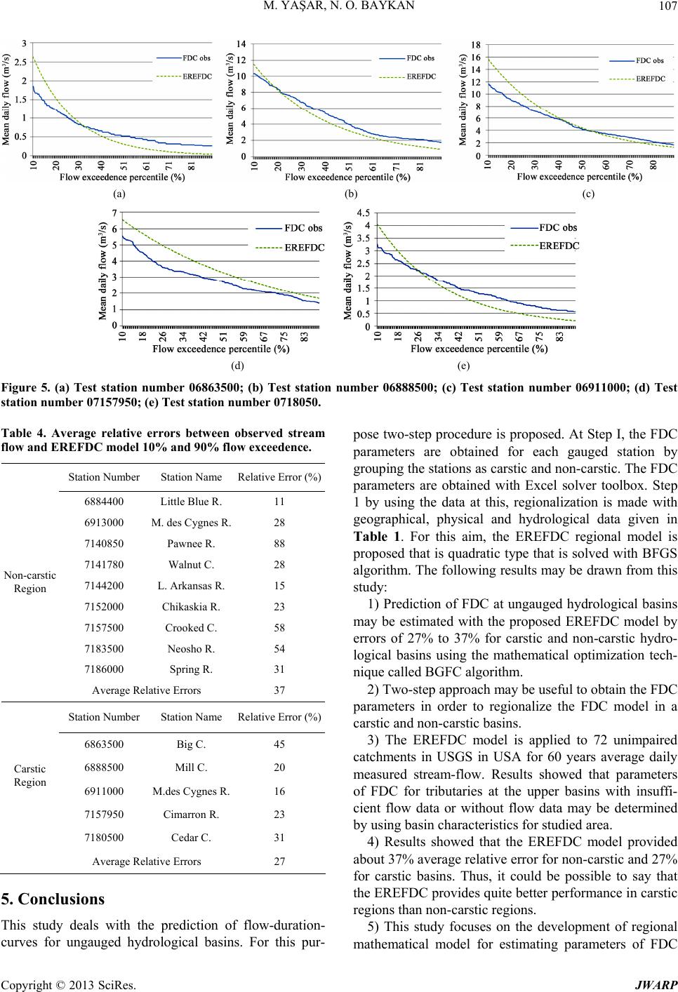 M. YAŞAR, N. O. BAYKAN 107 (a) (b) (c ) (d) Figure 5. (a) Test stat ation number 07157 (e) ion number 06863500; (b) Test station number 06888500; (c) Test station number 06911000; (d) Test 950; (e) Test station number 0718050. Table 4. Average relative errors between observed stream flow and EREFDC model 10% and 90% flow exceedence. Station Number Station Name Relative Error (%) st 6884400 Little Blue R. 11 6913000 M. des Cygnes R. 28 7140850 Pawnee R. 88 7141780 W 7144200 L. Arkansas R. 15 7152000 Chikaskia R. 23 7157500 Crooked C. 58 7183500 Neosho R. 54 7186000 Spring R. 31 Non-carstic Region Average Relative Errors 37 Station N alnut C. 28 umber Station Name Relative Error (%) 6863500 Big C. 45 6888500 Mill C. 20 6911000 M.des Cygnes R. 16 7157950 Cimarron R. 23 Carstic Region 7180500 Cedar C. 31 Average Relative Errors 27 5. Conclusions pose two-step procedure is proposed. At Step I, the FDC parameters are obtained for each gauged station by grouping the stations as carstic and non-carstic. The FDC parameters are obtained with Excel solver toolbox. Step 1 by using the data at this, regionalization is made with geographical, physical and hydrological data given in Table 1. For this aim, the EREFDC regional model is with BFGS algorithm. The following results may be drawn from this study: 1) Prediction of FDC at ungauged hydrological basins may be estimated with the proposed EREFDC model by errors of 27% to 37% for carstic and non-carstic hydro- logical basins using the mathematical optimization tech- nique called BGFC algorithm. 2) Two-step approach may be useful to obtain the FDC parameters in order to regionalize the FDC model in a 3) The EREFDC model is applied to 72 unimpaired catchments in USGS in USA for 60 years average daily measured stream-flow. Results showed that parameters of FDC for tributaries at the upper basins with insuffi- cient flow data or without flow data may be determined by using basin characteristics for studied area. 4) Results showed that the EREFDC model provided about 37% average relative error for non-carstic and 27% for carstic basins. Thus, it could be possible to say tha nce in carstic model for estimating parameters of FDC This study deals with the prediction of flow-duration- curves for ungauged hydrological basins. For this pur- regions than non-carstic regions. 5) This study focuses on the development of regional mathematical proposed that is quadratic type that is solved carstic and non-carstic basins. t the EREFDC provides quite better performa Copyright © 2013 SciRes. JWARP  M. YAŞAR, N. O. BAYKAN 108 curves for carstic and non-carstic regions. The average relative errors may be considered as a quite high for non- carstic regions. Future studies should be improvement on the prediction performance of the ERFDC model for un- controlled steam flows for various data in the world. REFERENCES [1] R. M. Vogel and N. M. Fennessey, “Flow Duration Cur- ves II: A Revi Planning,” Journal of the American Water Resources As- sociation, Vol. 31, No. 6, 1995, pp. 1029-1039. doi:10.1111/j.1752-1688.1995.tb03419.x ew of Applications in Water Resources [2] C. C. Warnick, “Hydropower Engineering,” Englewood Cliffs, New Jersey, 1984. [3] D. R. Maidment, “Handbook of Hydrology,” McGraw- Hill, Colombus, 1992. [4] N. Fennessey and R. M. Vogel, “Regional Flow Duration Curves for Ungauged Sites in Massachusetts,” Journal of Water Resources Planning and Management No. 4, 1990, pp. 530-549. , Vol. 116, doi:10.1061/(ASCE)0733-9496(1990)116:4(530) [5] M. Mimikou and S. Kaemaki, “Regionalization of Flow Duration Characteristics,” Journal of Hydrology, Vol. 82, No. 1-2, 1985, pp. 77-91. doi:10.1016/0022-1694(85)90048-4 [6] A. Alkr Kl zeyli ASa A lerinin Msi,” idroloji ngresi, İzmir, 2001 [7] R. D. Singh, y, “Regional Flow-Durels fomber of auged Himalayan Catchments for Planning Microhydrojects, l ogic El. 6, No 2001, 10-31 doi:10.106 )1084:4(310) an, “Karst Pina kişli Çevirme atkili Akarsu ntralları için arda, Serbest Yü- kım Sürek Eğri- odellenmeIII. Ulusal HKo , pp. 247-255. S. K. Mishra ation Mod and H. Chowdhar r Large NuUng ro P Journa pp. 3 f Hydrolo 6. ngineering, Vo. 4, 1/(ASCE -0699(2001)6 [8] P. S. Yu Yangy Analy gional Flon Curvl of Water Resources Planning ageme8, No. 6,2, pp. 424-430. doi:10.1061 02)128:6(424 and T. C., “Uncertaintsis of Re- w Duratio and Man es,” Journa nt, Vol. 12 200 /(ASCE)0733-9496(20 ) [9] M. Franchini and M. Suppo, “Regional Analysis of Flow Duratioa g sources Management, Vol. 10, No. 3, 1996, pp. 199-218. doi:10.100 4203 n Curves for Limestone Reion,” Water Re- 7/BF0042 [1 . Yu aang, “S Regional Flow Dura- Curve forical Processes, Vol. 10, N, pp doi:10.100099-110:3<37 ID-H 0] P. S tion nd T. C. Yynthetic Southern o. 3, 1996 Taiwan,” Hydrolog . 373-391. 2/(SICI)1 085(199603)3::A YP306>3.0.CO;2-4 [11] K. M. Crocker, Young H. G. Rees uration Cemeral Catc Portugal,” Hydrological Sciences, Vol. 48, No. 3, 2003, :10.1623/hysj.48.3.427.45287 M. D. Z. and, “Flow Durve Estimation in Ephhments in pp. 427-439. doi n and D. J. Robinson, “The [13] I. Krasovskaia, I. Gottschalk, E. Leblois and A. Pacheco, “Regionalization of Flow Duration Curves,” In: S. De- muth, Ed., Climate Variability and Change-Hydrologi- cal Impacts, IAHS Press, Wallingford, 2006. [14] M. F. Bari and Kh. M. D. S. Islam, “Stochastic Model of Flow Duration Curves for Selected Rivers in Bangla- desh,” Proceedings of the 5th FRIEND World Confer- ence on Climate Variability and Change-Hydrological Impacts, Havana, 27 November-1 December 2006, pp. 99-104. rve Estimation in Small Ungauged Catchments Using Instantaneous Flow Measurements and a Censored Data Approach,” Journal of Hydrology, Vol. 314, No. 1-4, 2005, pp. 48-66. doi:10.1016/j.jhydrol.2005.03.009 [12] R. A. J. Cole, H. T. Johnsto Use of Flow Duration Curves as a Data Quality,” Hydro- logical Sciences, Vol. 48, No. 6, 2003, pp. 939-951. [15] I. A. Niadas, “Regional Flow Duration Cu [16] A. Castellarin, G. Galeati, L. Brandimatre, A. Montanari and A. Brath, “Regional Flow-Duration Curves: Reliabil- ity for Ungauged Basins,” Advances in Water Resources, Vol. 27, No. 10, 2004, pp. 953-965. doi:10.1016/j.advwatres.2004.08.005 i, Z. Lu and H. S. C Francis, “A New proach and Its Application to Predict doi:10.1016/j.jhydrol.2010.05.039 [17] L. Ming, S. Quanx Regionalization Ap . Flow Duration Curve in Ungauged Basins,” Journal of Hydrology, Vol. 389, No. 1-2, 2010, pp. 137-145. [18] D. Ganora, P. Claps, F. Laio and A. Viglione, “An Ap- proach to Estimate Nonparametric Flow Duration Curves in Ungauged Basins,” Water Resources Research, Vol. 45, 2009, W10418. doi:10.1029/2008WR007472 [19] Y. Yokoo and M. Sivapalan, “Towards Reconstruction of the Flow Duration Curve: Development of a Conceptual Framework with a Physical Basis,” Hydrology and Earth System Sciences, Vol. 15, No. 9, 2011, pp. 2805-2819. [20] F. Viola, L. V. Noto, M. Cannarozzo and G. La Loggia, “Regional Flow Duration Curves for Ungauged Sites in Sicily,” Hydrology and Earth System Sciences, Vol. 15, er-Resources Investigations, cy Characteristics at Un- ny Search Algorithm,” No. 1, 2011, pp. 323-331. [21] Microsoft, “Microsoft Excel-Visual Basic for Applica- tions,” Microsoft Press, Washington DC, 1995. [22] H. C. Riggs, “Low-Flow Investigations,” US Geological Survey Techniques of Wat Washington DC, 1972. [23] L. C. Kjelstrom, “Methods for Estimating Selected Flow- Duration and Flood-Frequen gauged Sites in Central Idaho,” USGS Water Resources Investigations Report 94-4120, Boise, 1998, p. 10. [24] S. E. Studley, “Estimated Flow Duration Curves for Se- lected Ungauged Sites in Kansas,” US Geological Survey, 01:4142, Virginia, 2001. [25] J. Nocedal and S. J. Wright, “Numerical Optimization,” Springer-Verlag, Berlin, 2006. [26] J. S. Arora, “Introduction to Optimum Design,” McGraw- Hill, New York, 1989. [27] H. Karahan, G. Gurarslan and Z. W. Geem, “Parameter Estimation of the Nonlinear Muskingum Flood Routing Model Using a Hybrid Harmo Journal of Hydrologic Engineering, 2012, in Press. doi:10.1061/(ASCE)HE.1943-5584.0000608 Copyright © 2013 SciRes. JWARP  M. YAŞAR, N. O. BAYKAN Copyright © 2013 SciRes. JWARP 109 [28] C. A. Perry, D. M. Volock and J. C. Artman, “Estimates of Flow Duration, Mean Flow and Peak-Discharge Fre- quency Values for Kansas Stream Location,” Scientific Investigation Report 2004-5033, US Geological Survey, Virginia, 2004.  M. YAŞAR, N. O. BAYKAN 110 Appendix: Example average daily flow for Turkey C. station. 06814000 - TURKEY C NR SENECA, KS Daily Mean Flows for 62 years Jan Feb Mar Apr May Jun Jul Aug Sep Oct Nov Dec 1 0.79 2.89 4.96 8.27 6.26 4.53 9.26 1.81 1.42 3.34 1.30 1.27 2 0.79 2.32 4.33 5.10 5.15 9.01 5.30 1.81 3.82 4.56 3.17 0.88 3 0.76 1.90 7.02 8.67 3.26 5.49 3.12 2.38 3.09 4.30 2.10 0.79 4 0.74 2.24 4.45 6.23 3.09 5.15 5.07 2.10 8.04 1.56 1.84 0.82 5 0.74 1.78 5.41 4.96 4.25 3.51 9.23 1.08 5.04 1.19 1.10 0.85 6 0.76 1.67 4.13 4.11 6.83 6.03 5.89 2.83 3.74 1.56 0.88 0.74 7 0.85 1.67 3.14 3.00 14.30 6.17 9.40 4.16 5.30 2.12 0.96 0.74 8 1.05 1.50 2.49 2.80 14.02 4.87 4.05 4.16 2.66 1.87 1.22 1.02 9 0.88 1.47 3.09 3.09 10.56 5.64 5.86 1.73 4.59 2.32 1.98 0.85 10 0.93 1.42 3.94 3.12 6.97 8.18 4.90 1.53 2.72 3.91 1.44 0.82 11 0.79 1.81 5.58 4.13 5.66 5.04 10.54 1.81 1.42 10.85 0.91 1.02 12 1.19 2.10 5.95 4.02 4.59 7.39 7.90 1.70 6.71 7.08 1.25 1.19 13 1.81 2.24 4.81 3.00 7.90 6.66 5.75 2.21 6.57 2.44 1.39 1.02 14 1.13 2.21 5.66 5.78 3.17 5.52 3.85 1.98 2.86 2.07 1.08 1.30 15 1.56 2.18 3.77 8.30 5.69 9.88 3.43 3.03 2.24 5.30 0.82 1.05 16 1.08 2.55 3.34 4.13 5.75 9.23 2.24 1.78 2.52 1.76 1.84 0.85 17 1.36 3.09 3.68 5.35 8.67 5.81 2.78 1.44 4.08 1.44 2.24 0.85 18 1.27 4.76 8.95 5.55 4.64 10.54 8.04 1.33 1.61 1.67 1.36 0.91 19 1.05 5.24 8.47 2.95 4.79 6.60 3.60 1.84 2.04 1.13 1.84 1.08 20 0.96 3.94 3.77 3.57 4.05 3.74 6.74 2.04 2.61 1.33 1.73 0.85 21 1.05 2.80 3.34 5.61 8.44 6.06 3.14 1.47 3.46 1.25 1.53 0.79 22 1.02 2.18 3.34 4.98 9.01 5.38 6.37 1.93 2.49 1.13 1.10 0.76 23 1.13 2.49 5.07 3.57 7.05 5.55 6.46 1.42 2.15 1.05 0.85 0.85 24 1.70 4.47 5.38 3.94 6.32 5.75 4.16 2.35 1.67 1.02 1.47 0.88 25 1.16 4.08 6.66 4.73 5.10 7.11 9.86 2.27 2.21 0.71 0.99 1.19 26 1.44 3.96 5.89 4.39 7.31 4.70 4.87 1.67 2.78 0.76 0.99 0.88 27 2.01 3.88 8.10 8.86 7.59 4.96 2.86 1.39 4.02 0.74 0.88 1.08 28 1.93 4.08 9.32 3.60 5.30 6.83 3.40 2.41 3.06 0.68 0.79 0.93 29 1.95 1.05 6.40 3.68 5.04 14.67 1.42 2.55 4.53 0.85 0.79 0.93 30 1.87 10.22 5.30 6.94 6.00 2.44 2.52 2.83 1.56 1.16 1.42 31 1.53 10.68 7.59 2.04 0.93 1.44 1.02 Copyright © 2013 SciRes. JWARP |