Paper Menu >>
Journal Menu >>
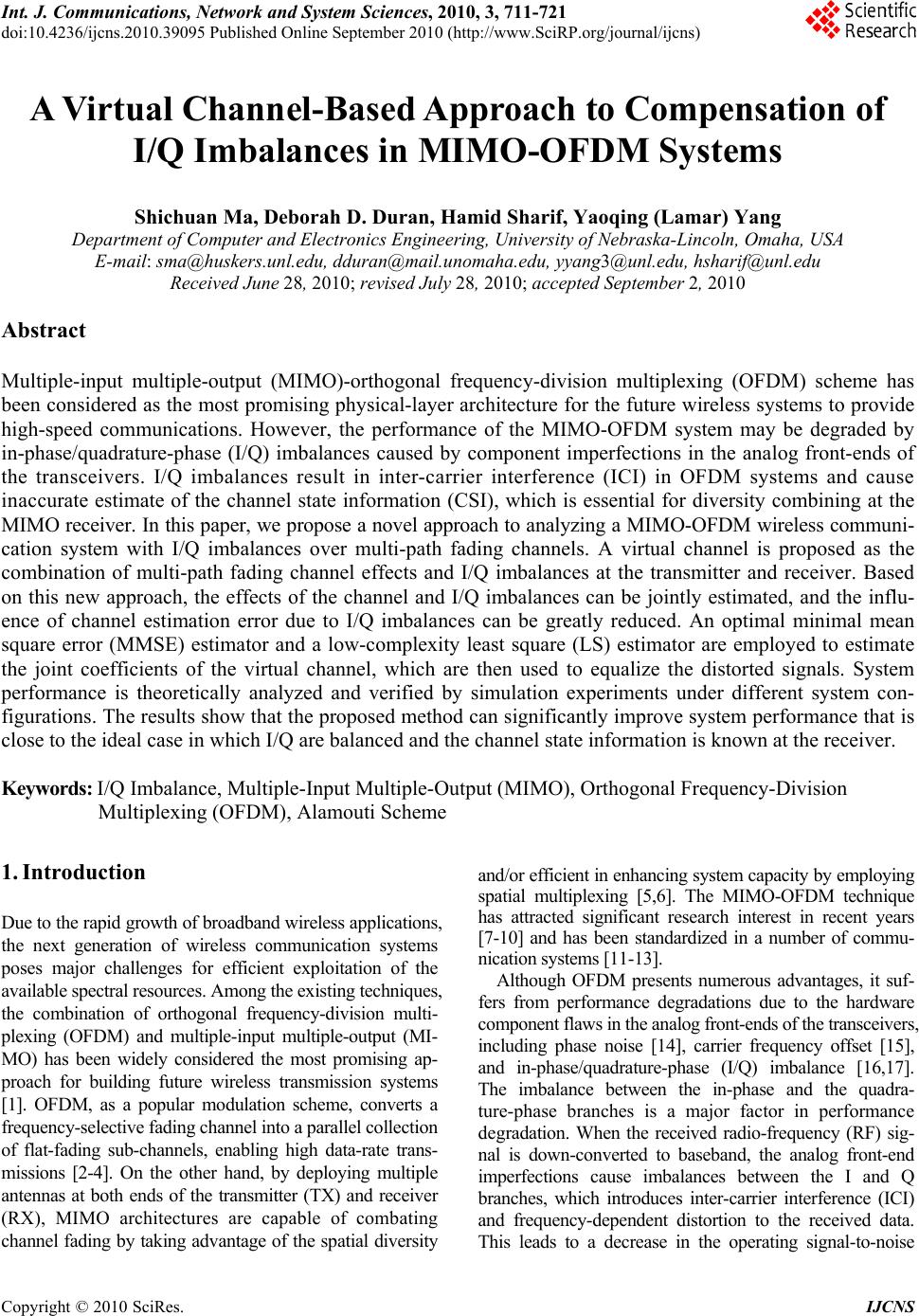 Int. J. Communications, Network and System Sciences, 2010, 3, 711-721 doi:10.4236/ijcns.2010.39095 Published Online September 2010 (http://www.SciRP.org/journal/ijcns) Copyright © 2010 SciRes. IJCNS A Virtual Channel-Based Approach to Compensation of I/Q Imbalances in MIMO-OFDM Systems Shichuan Ma, Deborah D. Duran, Hamid Sharif, Yaoqing (Lamar) Yang Department of C omput er and Electronics Engineering, University of Nebr aska-Lincoln, Oma ha, USA E-mail: sma@huskers.unl.edu, dduran@mail.unomaha.edu, yyang3@unl.edu, hsharif @unl.edu Received June 28, 2010; revised July 28, 2010; accepted September 2, 2010 Abstract Multiple-input multiple-output (MIMO)-orthogonal frequency-division multiplexing (OFDM) scheme has been considered as the most promising physical-layer architecture for the future wireless systems to provide high-speed communications. However, the performance of the MIMO-OFDM system may be degraded by in-phase/quadrature-phase (I/Q) imbalances caused by component imperfections in the analog front-ends of the transceivers. I/Q imbalances result in inter-carrier interference (ICI) in OFDM systems and cause inaccurate estimate of the channel state information (CSI), which is essential for diversity combining at the MIMO receiver. In this paper, we propose a novel approach to analyzing a MIMO-OFDM wireless communi- cation system with I/Q imbalances over multi-path fading channels. A virtual channel is proposed as the combination of multi-path fading channel effects and I/Q imbalances at the transmitter and receiver. Based on this new approach, the effects of the channel and I/Q imbalances can be jointly estimated, and the influ- ence of channel estimation error due to I/Q imbalances can be greatly reduced. An optimal minimal mean square error (MMSE) estimator and a low-complexity least square (LS) estimator are employed to estimate the joint coefficients of the virtual channel, which are then used to equalize the distorted signals. System performance is theoretically analyzed and verified by simulation experiments under different system con- figurations. The results show that the proposed method can significantly improve system performance that is close to the ideal case in which I/Q are balanced and the channel state information is known at the receiver. Keywords: I/Q Imbalance, Multiple-Input Multiple-Output (MIMO), Orthogonal Frequency-Division Multiplexing (OFDM), Alamouti Scheme 1. Introduction Due to the rapid growth of broadband wireless applications, the next generation of wireless communication systems poses major challenges for efficient exploitation of the available spectral resources. Among the existing techniques, the combination of orthogonal frequency-division multi- plexing (OFDM) and multiple-input multiple-output (MI- MO) has been widely considered the most promising ap- proach for building future wireless transmission systems [1]. OFDM, as a popular modulation scheme, converts a frequency-selective fading channel into a parallel collection of flat-fading sub-channels, enabling high data-rate trans- missions [2-4]. On the other hand, by deploying multiple antennas at both ends of the transmitter (TX) and receiver (RX), MIMO architectures are capable of combating channel fading by taking advantage of the spatial diversity and/or efficient in enhancing system capacity by employing spatial multiplexing [5,6]. The MIMO-OFDM technique has attracted significant research interest in recent years [7-10] and has been standardized in a number of commu- nication systems [11-13]. Although OFDM presents numerous advantages, it suf- fers from performance degradations due to the hardware component flaws in the analog front-ends of the transceivers, including phase noise [14], carrier frequency offset [15], and in-phase/quadrature-phase (I/Q) imbalance [16,17]. The imbalance between the in-phase and the quadra- ture-phase branches is a major factor in performance degradation. When the received radio-frequency (RF) sig- nal is down-converted to baseband, the analog front-end imperfections cause imbalances between the I and Q branches, which introduces inter-carrier interference (ICI) and frequency-dependent distortion to the received data. This leads to a decrease in the operating signal-to-noise 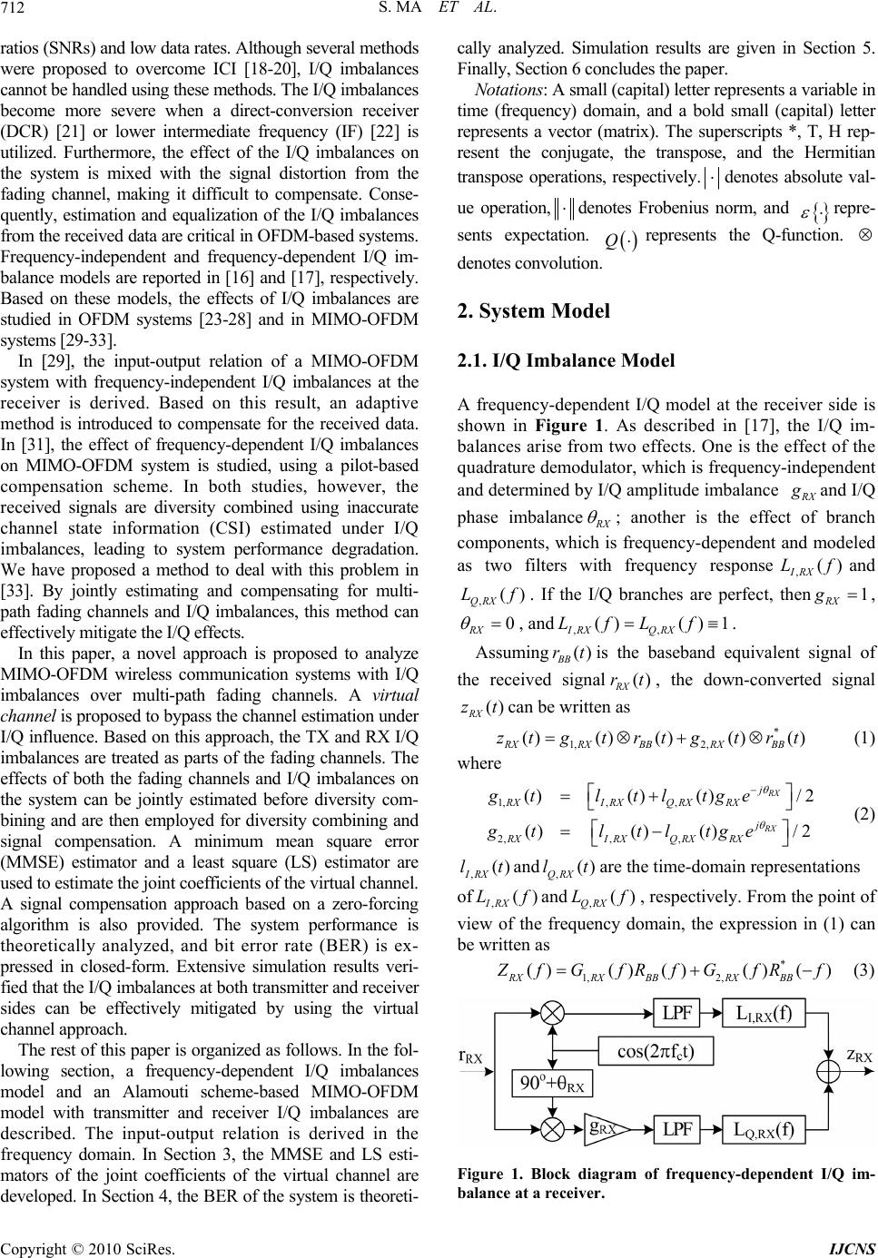 S. MA ET AL. Copyright © 2010 SciRes. IJCNS 712 ratios (SNRs) and low data rates. Although several methods were proposed to overcome ICI [18-20], I/Q imbalances cannot be handled using these methods. The I/Q imbalances become more severe when a direct-conversion receiver (DCR) [21] or lower intermediate frequency (IF) [22] is utilized. Furthermore, the effect of the I/Q imbalances on the system is mixed with the signal distortion from the fading channel, making it difficult to compensate. Conse- quently, estimation and equalization of the I/Q imbalances from the received data are critical in OFDM-based systems. Frequency-independent and frequency-dependent I/Q im- balance models are reported in [16] and [17], respectively. Based on these models, the effects of I/Q imbalances are studied in OFDM systems [23-28] and in MIMO-OFDM systems [29-33]. In [29], the input-output relation of a MIMO-OFDM system with frequency-independent I/Q imbalances at the receiver is derived. Based on this result, an adaptive me thod is introduced to compensate for the received data. In [31], the effect of frequency-dependent I/Q imbalances on MIMO-OFDM system is studied, using a pilot-based compensation scheme. In both studies, however, the received signals are diversity combined using inaccurate channel state information (CSI) estimated under I/Q imbalances, leading to system performance degradation. We have proposed a method to deal with this problem in [33]. By jointly estimating and compensating for multi- path fading channels and I/Q imbalances, this method can effectively m itigate th e I/Q ef fect s. In this paper, a novel approach is proposed to analyze MIMO-OFDM wireless communication systems with I/Q imbalances over multi-path fading channels. A virt ual channel is proposed to bypass the channel estimation under I/Q influence. Based on this approach, the TX and RX I/Q imbalances are treated as parts of the fading channels. The effects of both the fading channels and I/Q imbalances on the system can be jointly estimated before diversity com- bining and are then employed for diversity combining and signal compensation. A minimum mean square error (MMSE) estimator and a least square (LS) estimator are used to estimate the joint coefficients of the virtual channel. A signal compensation approach based on a zero-forcing algorithm is also provided. The system performance is theoretically analyzed, and bit error rate (BER) is ex- pressed in closed-form. Extensive simulation results veri- fied that the I/Q imbalances at both transmitter and recei ver sides can be effectively mitigated by using the virtual channel approach. The rest of this paper is organized as follows. In the fol- lowing section, a frequency-dependent I/Q imbalances model and an Alamouti scheme-based MIMO-OFDM model with transmitter and receiver I/Q imbalances are described. The input-output relation is derived in the frequency domain. In Section 3, the MMSE and LS esti- mators of the joint coefficients of the virtual channel are developed. In Section 4, the BER of the system is theoreti- cally analyzed. Simulation results are given in Section 5. Finally, Section 6 concludes the paper. Notatio ns: A small (capital) letter represents a variable in time (frequency) domain, and a bold small (capital) letter represents a vector (matrix). The superscripts *, T, H rep- resent the conjugate, the transpose, and the Hermitian transpose operations, respectively.denotes absolute val- ue operation, denotes Frobenius norm, and repre- sents expectation. Q represents the Q-function. denotes convolution. 2. System Model 2.1. I/Q Imbalance Model A frequency-dependent I/Q model at the receiver side is shown in Figure 1. As described in [17], the I/Q im- balances arise from two effects. One is the effect of the quadrature demodulator, which is frequency-independent and determined by I/Q amplitude imbalance R X g and I/Q phase imbalance R X ; another is the effect of branch components, which is frequency-dependent and modeled as two filters with frequency response,() IRX Lfand ,() QRX Lf. If the I/Q branches are perfect, then1 RX g , 0 RX , and,, ()() 1 IRX QRX LfLf . Assuming () BB rtis the baseband equivalent signal of the received signal() RX rt, the down-converted signal () RX ztcan be written as * 1, 2, ()() ()() () RXRX BBRX BB ztg trtgtrt (1) where 1,, , 2,, , ()() ()/2 ()() ()/2 RX RX j RXI RXQ RXRX j RXIRXQRXRX gtltltge gt ltltge (2) ,() IRX ltand ,() QRX ltare the time-domain representations of ,() IRX Lf and ,() QRX Lf , respectively. From the point of view of the frequency domain, the expression in (1) can be written as * 1, 2, ()()()()() RXRX BBRX BB Z fGfR fGfRf (3) Figure 1. Block diagram of frequency-dependent I/Q im- balance at a receiver. 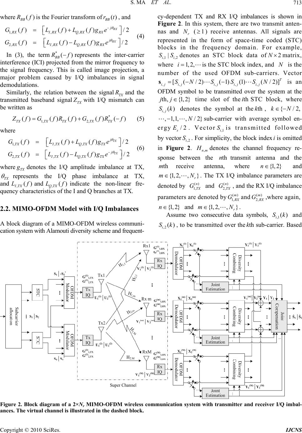 S. MA ET AL. Copyright © 2010 SciRes. IJCNS 713 where () BB Rfis the Fourier transform of() BB rt, and 1,, , 2,, , ()() ()/2 ()() ()/2 RX RX j RXIRXQ RXRX j RXIRXQ RXRX GfLfL fge Gf LfLfge (4) In (3), the term*() BB Rfrepresents the inter-carrier interference (ICI) projected from the mirror frequency to the signal frequency. This is called image projection, a major problem caused by I/Q imbalances in signal demodulations. Similarly, the relation between the signalTX Rand the transmitted baseband signalTX Z with I/Q mismatch can be written as * 1, 2, ()() ()() () TXTX TXTX TX Z fGfRf GfRf (5) where 1,, , 2,, , ()() ()/2 ()() ()/2 TX TX j TXITXQ TXTX j TXITXQTXTX GfLfL fge Gf LfLfge (6) where TX g denotes the I/Q amplitude imbalance at TX, TX represents the I/Q phase imbalance at TX, and ,() ITX Lfand,() QTX Lfindicate the non-linear fre- quency characteristics of the I and Q branches at TX. 2.2. MIMO-OFDM Model with I/Q Imbalances A block diagram of a MIMO-OFDM wireless communi- cation system with Alam outi dive rsity schem e and freq uent- cy-dependent TX and RX I/Q imbalances is shown in Figure 2. In this system, there are two transmit anten- nas and r N (1) receive antennas. All signals are represented in the form of space-time coded (STC) blocks in the frequency domain. For example, ,1 ,2 | ii SSdenotes an STC block data of2N matrix, where 1, 2,i is the STC block index, and N is the number of the used OFDM sub-carriers. Vector ,,, ,, [(/2)( 1)(1)(/2)] T ij ijijijij SNSSSN s is an OFDM symbol to be transmitted over the system at the th, {1,2}jj time slot of thethiSTC block, where ,() ij Sk denotes the symbol at thethk, {/2,kN ,1,1,, /2}N sub-carrier with average symbol en- ergy /2 s E. Vector,1i Sis transmitted followed by vector,2i S. For simplicity, the block indexiis omitted in Figure 2. ,nm H denotes the channel frequency re- sponse between the thntransmit antenna and the thmreceive antenna, where {1, 2}n and {1, 2,,} r mN . The TX I/Q imbalance parameters are denoted by () 1,n TX G and () 2, n TX G, and the RX I/Q imbalance parameters are denoted by() 1,m R X Gand () 2, m R X G,where again, {1, 2}n and {1, 2,,} r mN . Assume two consecutive data symbols, ,1 () i Sk and ,2() i Sk, to be transmitted over thethksub-carrier. Based Figure 2. Block diagram of a 2×Nr MIMO-OFDM wireless communication system with transmitter and receiver I/Q imbal- ances. The virtual channel is illustrated in the dashed block. 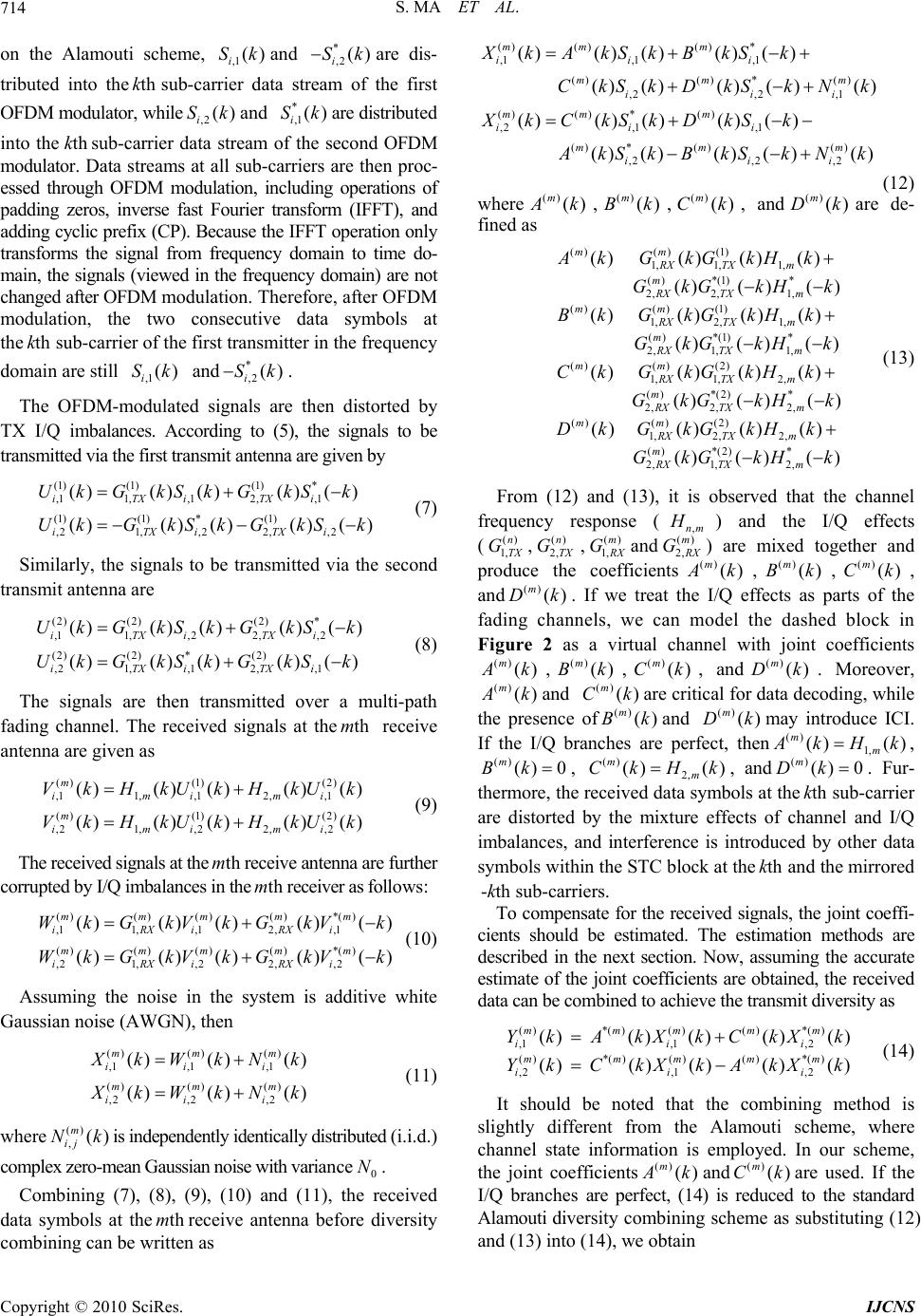 S. MA ET AL. Copyright © 2010 SciRes. IJCNS 714 on the Alamouti scheme, ,1 () i Skand * ,2() i Skare dis- tributed into thethksub-carrier data stream of the first OFDM modulator, while,2() i Skand * ,1 () i Skare distribute d into the thksub-carrier data stream of the second OFDM modulator. Data streams at all sub-carriers are then proc- essed through OFDM modulation, including operations of padding zeros, inverse fast Fourier transform (IFFT), and adding cyclic prefix ( CP). Because the IFFT operation only transforms the signal from frequency domain to time do- main, the signals (viewed in the frequ ency domain) are not changed after OFDM modulation. Therefore, after OFDM modulation, the two consecutive data symbols at the thksub-carrier of the first transmitter in the frequency domain are still ,1() i Sk and* ,2() i Sk. The OFDM-modulated signals are then distorted by TX I/Q imbalances. According to (5), the signals to be transmitted via the first transmit antenna are given by (1)(1)(1) * ,11, ,12, ,1 (1)(1) *(1) ,21,,2 2, ,2 ()()()()( ) ()()()() () iTXiTXi iTXiTXi UkGkSkGkSk UkG kSkGkSk (7) Similarly, the signals to be transmitted via the second transmit antenna are (2)(2)(2) * ,11, ,2 2,,2 (2)(2) *(2) ,21,,1 2,,1 ()() ()() () ()() ()() () iTXiTXi iTXiTXi UkG kSkGkSk UkG kSkGkS k (8) The signals are then transmitted over a multi-path fading channel. The received signals at thethm receive antenna are given as () (1) (2) ,11, ,12, ,1 () (1) (2) ,21,,22, ,2 ()() ()()() ()() ()()() m imimi m imimi VkHkUkHkUk VkHkUkHkUk (9) The received signals at thethmreceive antenna are further corrupted by I/Q imbalances in thethmreceiver as follows: ()()()()*() ,11, ,12, ,1 ()()()()*() ,21, ,22, ,2 ()()()()() ()()()()() mmmmm iRXiRXi mmmmm iRXiRXi WkGkVkGkVk WkGkVkGkVk (10) Assuming the noise in the system is additive white Gaussian noise (AWGN), then ()() () ,1 ,1,1 ()() () ,2 ,2,2 ()() () ()() () mmm iii mmm iii X kWkN k X kWkN k (11) where() ,() m ij Nkis indepe ndently ide ntically distributed (i.i.d.) complex zero-mean Gaussian noise with variance0 N. Combining (7), (8), (9), (10) and (11), the received data symbols at thethmreceive antenna before diversity combining can be written as ()()() * ,1,1 ,1 ()() *() ,2,2 ,1 ()() *() ,2,1,1 () *()() ,2,2 ,2 ()()()() () () ()() ()() ()() ()() () () ()() ()() mm m iii mm m iii mm m iii mm m iii XkAkSkBkSk CkSkDkS kNk XkCkSkDkSk A kS kBkSkNk (12) where () () m A k,() () m Bk,() () m Ck, and() () m Dkare de- fined as ()() (1) 1, 1,1, () *(1)* 2, 2,1, ()() (1) 1, 2, 1, () *(1)* 2, 1,1, ()() (2) 1, 1,2, () *(2) 2, 2, ()()() () ()( )() ()()()() ()( )( ) ()()() () () ( mm RX TXm m RX TXm mm RX TXm m RX TXm mm RX TXm m RX TX AkGkGkHk GkGkHk Bk G kG kHk GkG kHk Ck G kGkHk GkG k * 2, ()() (2) 1, 2,2, () *(2)* 2, 1,2, )() ()()()() ()() () m mm RX TXm m RX TXm H k DkGkG kHk GkGkHk (13) From (12) and (13), it is observed that the channel frequency response (,nm H ) and the I/Q effects (() 1,n TX G,() 2, n TX G,() 1,m R X Gand () 2, m R X G) are mixed together and produce the coefficients() () m A k,() () m Bk,() () m Ck, and () () m Dk. If we treat the I/Q effects as parts of the fading channels, we can model the dashed block in Figure 2 as a virtual channel with joint coefficients () () m A k,() () m Bk,() () m Ck, and() () m Dk. Moreover, () () m A kand () () m Ckare critical for data decoding, while the presence of() () m Bkand () () m Dkmay introduce ICI. If the I/Q branches are perfect, then() 1, () () mm A kHk, () () 0 m Bk , ()2, () () mm CkHk, and() () 0 m Dk . Fur- thermore, the received data symbols at thethksub-carrier are distorted by the mixture effects of channel and I/Q imbalances, and interference is introduced by other data symbols within the STC block at thethkand the mirrored -thksub-carriers. To compensate for the received signals, the joint coeffi- cients should be estimated. The estimation methods are described in the next section. Now, assuming the accurate estimate of the joint coefficients ar e obtained, the rece ived data can be combined to achieve the transmit diversity as ()*() ()() *() ,1,1 ,2 ()*() ()() *() ,2,1,2 ()() ()()() ()() ()()() mmmmm iii mmmmm iii YkAkXkCkX k YkC kXkAkXk (14) It should be noted that the combining method is slightly different from the Alamouti scheme, where channel state information is employed. In our scheme, the joint coefficients() () m A kand () () m Ckare used. If the I/Q branches are perfect, (14) is reduced to the standard Alamouti diversity combining scheme as substituting (12) and (13) into (14), we obtain  S. MA ET AL. Copyright © 2010 SciRes. IJCNS 715 ()*()*() ,11, ,12, ,2 ()*()*() ,22, ,11, ,2 ()() ()()() ()() ()()() mm m imimi mmm imimi YkHkXkHkX k YkHkXkHkX k (15) ()()() * ,11,12,1 () *() 3,2 ,1 ()()*() * ,21 ,2 2,2 *( )*( ) 3,1 ,2 ()() ()() () ()()() ()() ()() () ()()() mm m iii mm ii mm m iii mm ii YkQkSkQkS k QkSkNk YkQkSkQkSk QkSkNk (16) where ()() 2() 2 1 ()*() ()()*() 2 ()*()()() *() 3 () |()||()| ()() ()()() ()() ()()() mm m mmmmm mmmmm Qk AkCk QkA kBkCkDk QkA kDkCkBk (17) and ()*()()() *() ,1,1 ,2 ()*() ()() *() ,1,1 ,2 ()() ()()() ()() ()()() mmmmm iii mmmmm iii NkAknkCknk NkCknkAknk (18) Finally, the received data symbols at multiple receive antennas are combined to obtain receiv er diversity, and the raw data symbols are given by () ,1 ,1 1 *()* 1,1 2,13 ,2,1 () ,2 ,2 1 1,2 2 signalintercarrier interferenceno i se signal () () ()()()( )()( )() () () ()()() r r Nm ii m m ii ii Nm ii m ii YkYk QkSk QkSk QkSkNk YkY k QkS kQkS **()* ,23,1,2 intercarrier interferencenoise ()()() () mii kQkSkNk (19) where () 11 1 () 22 1 () 33 1 () () () () () () r r r Nm m Nm m Nm m QkQ k QkQ k QkQk (20) are defined as the combined coefficients, and () ,1 ,1 1 () ,2 ,2 1 () () () () r r Nm ii m Nm ii m NkN k NkN k (21) are the combined noise. From (19), it can be seen that there is ICI in the signals after receiver combining, which is caused by the image projections from the mirrored frequency. To improve system performance, it is necessary to compensate for the received signals. 3. Estimators and Signal Compensation In this section, we describe two training sequence-based estimators to show how to estimate the joint coefficients of the virtual channel. The first is a minimal mean square error (MMSE) estimator. Although MMSE estimator is an optimal linear detector, it requires some priori know- ledge of the estimated variables and is computationally intensive. An alternative is a least square (LS) estimator, which may significantly reduce the computational com- plexity at the expense of negligible BER degradation. The estimated joint coefficients can be used to perform diversity combining as in (14) and to compensate for the received signals as described at the end of this section. 3.1. MMSE Estimator Assume totaltr Nblocks of training sequences are used in this system (That is2tr NOFDM symbols). Let,() ij Pk, {1, 2}j denote thethjtraining symbol in thethiblock at thethk sub-carrier. According to (12), the in- put-output relation for one block can be written as ()() () ()() ()() mmm ii i kkk kuPvn (22) where ()() () ,1 ,2 ()() ()T mmm iii kXkXk u (23) ** ,1,1,2 ,2 ** ,2,2,1 ,1 ()()()( ) () ()()() () ii ii iiiii PkPk PkPk kPk PkPkP k P (24) ()()()()() ()() () ()()T mmmmm ikAkB kCkDk v (25) ()()() ,1 ,2 ()() ()T mmm iii kNkNk n (26) For the totalTblocks, the input-output relation is written as ()() () () () ()() mmm kkk kuPvn (27) where ()()()() 12 ()() ()() tr T mmTmTmT N kkk k uuu u (28) 12 ()() ()() tr TT T N kkk k PPPP (29) ()()()() 12 ()() ()() tr T mmTmTmT N kkk k nnn n (30) The MMSE estimate ofvis given as [34] () 1() ˆ() () mm vu u kk vRRu (31) where () () {()()} () mmH H vu v Ekk kRvu RP (32) () () {()()}()() mmH H uvn Ekkk kRuuPRP R (33) () ()02 {()()} mmH nT EkkNRnn I (34) () () {() ()} mmH vEkkRvv (35)  S. MA ET AL. Copyright © 2010 SciRes. IJCNS 716 3.2. LS Estimator Although MMSE estimator is optimal, it suffers from h igh co mputational complex ity and requires th e knowled g e of v R, which must be estimated using a large amount of transmission data. A simple but effective method is least square estimator. To further reduce the computational complexity, we design a special training pattern to avoid matrix inversion operation. In order to utilize this special pattern, training sequences must be transmitted in groups of two blocks. Let s , s , s , and * s be the four consecutive training symbols within the thiand the(1)thiST C blocks at thethksub-carrier, where(1 ) s pjis a com- plex number with identical real and imaginary partsp. The corresponding training symbols at thethksub-carrier are also s , s , s , and* s . According to (12), the received data within thethiand the(1)thiSTC blocks at the thksub-carrier can be represented in matrix form as () () ** ,1 ,1 () () ** ,2 ,2 () () () ** 1,1 1,1 () () ** 1,2 1,2 () () () () () () () () () mm ii mm ii m mm ii mm ii X kNk ssss X kNk ssssk X kNk ssss X kNk ssss v (36) Thus, the LS estimate of the joint coefficients is given as [35] 1() ** ,1 () ** ,2 () () ** 1,1 () ** 1,2 () ,1 () ,2 () 1,1 () 1,2 () () ˆ() () () 01 1() 01 1() 1 10 1() 4 10 1() m im i mm im i m im im im i Xk ssss Xk ssss kXk ssss Xk ssss jj X k jj X k jj X k p jj X k v (37) The estimates of the virtual channel coefficients from different training sequence groups can be averaged to obtain more accurate estimate. 3.3. Signal Compensation Approach Based on the MMSE estimate given by (31) or LS estimate given by (37) of the joint coefficients, the estimate of the combined coefficients, 1 ˆ()Qk,2 ˆ()Qk, and3 ˆ()Qk, can be calculated according to (17) and (20) , and then can be used to equalize the raw data symbols. According to (19), the raw data symbols at thethkand the ()thksub-carriers within thethiSTC block can be written in matrix form as (38). Thus, the zero-forcing estimates of the transmitted data symbols are given by (39). ,1 * ,1 ,2 * ,2 123 1,1 **** 2131 , ** 2 31 2* *2 321 () () () () ˆˆ ˆ ()()0()() () ˆˆˆ ()()()0() ˆˆˆ () 0()()() () ˆˆˆ ()0() () i i i i i i Yk Yk Yk Yk Qk QkQkSk N k QkQkQkSk N Sk Qk QkQkSk Qk QkQk 1 ,2 ,2 () () () i i k N k N k (38) 1 12 31,1 * ****,1 213 1 ** ,2 31 22* ** ,2 321 2 ˆˆ ˆˆ()()0() () () ˆˆˆ ˆ() ()() ()0() ˆˆˆˆ() 0()()() () () ˆˆˆ ˆ()0() ()() i i i i Qk QkQk Sk Yk Yk QkQkQkSk Yk Qk QkQk Sk Yk Qk QkQkSk (39) 4. Performance Analysis According to (19), the received raw data symbols are contaminated by noise and interference from the signals at the mirrored sub-carriers. If the ICI can be success- fully canceled by the proposed algorithm, the post- proc- essing SNR at thethksub-carrier, ()k , can be calcu- lated as 22 1,1 1,2 22 ,1 ,2 () 2() 2 10 () 2() 2 1 |()()||() ()| () |()||( )| /2 |( )||( )| 1|()||()| 2 r r ii ii Nmm s m Nmm m QkS kQkSk knk nk E AkCk N Ak Ck (40) where /2 s Eis the average transmit energy per symbol period per antenna and0 / s EN can be interpreted as the average SNR for the single-input single-output scheme. This post-processing SNR is determined by the joint effects of channels and I/Q imbalances. For classical i.i.d. channels [5] and perfect I/Q characteristics, the post- processing SNR becomes () r kN (41) This shows that the system with perfect I/Q over i.i.d. channel can achieve an array gain ofr N. In OFDM systems, each sub-carrier can be treated as a frequency-flat channel. Assuming optimum detection at the receiver, the corresponding symbol error rate for rectangular -a ryMQAM is given by [36]  S. MA ET AL. Copyright © 2010 SciRes. IJCNS 717 2 13() ()11 211 sk PkQ M M (42) Assuming that only one single bit is changed for each erroneous symbol, the equivalent bit error rate for rec- tangular -aryMQAM is approximated as [37] 2 1 () () () bs Pk Pk log M (43) 5. Simulation Results To evaluate the proposed virtual channel idea, the two estimators, and the signal compensation approach, we used MATLAB to simulate an OFDM-based2r N MI- MO system with frequency-dependent TX and RX I/Q imbalances. The size of fast Fourier transform (FFT) is 128, the number of used sub-carriers is 96, and the length of CP is 32. The multi-path channel is modeled by six in- dependent complex taps with a power delay profile of a 3 dB decay per tap. It should be noted that the actual channel length can be estimated [38]. The simulation bandwidth is set to 20 MHz, leading to a 156.25 KHz sub-carrier spac- ing and a maximum 0.3 s excess delay. Sixty-four qua- drature amplitude modulations (64QAM) are used. The non-linear frequency characteristics of the I and Q branches, () I Lfand( ) Q Lf, are modeled as two first- order finite impulse response (FIR) filters. A form of parameters ,,[ ,],[,] II QQ g ab ab is used to describe the I/Q imbalance, where[,] I I aband[ ,] QQ abare the co- efficients of the FIR filters for the I and Q branches. I/Q parameters of 1.03,3,[0.01,0.9],[0.8,0.02] and [0.8,0.02],[0.01,0.9] are used for the two transmitters, respectively. For simplification of simulation, all receivers use I/Q parameters of 1.05,3,[0.8,0.02],[0.9,0.01]. Because the estimation of the joint coefficients is per- formed separately in each receiver, the same I/Q pa- rameters for different I/Q models still lead to generaliza- tion of the simulation results. It should be noted that the I/Q imbalance parameters are chosen to be worst case in order to evaluate the robustness of the proposed app ro ach. A frame-by-frame transmission scheme is employed in the simulation. The multi-path channel is independently generated for each frame. One frame consists of tr N STC blocks of training symbols followed by 50 STC blocks of data symbols. A total of 5,000 frames (288 Mbits) are simulated for each scenario at a given SNR. Figure 3 shows the frequency response of two of the FIR filters used for simulating the frequency-dependent characteristics of I/Q imbalances. For both filters, the variations of the amplitude are within 0.5 dB, but the average g ains are d ifferentiated b y 1 dB. It shou ld be noted that the signals after TX I/Q distortions must be nor malized in the simulations to compensate for the energy lost due to attenuations of the filters. While the variation of the phase response for the first filter is small, the variation is very large for the second filter. The amplitude and phase differ- ences of the filters are suitable to simulate the fre- quency-dependent characteristics of I/Q imbalances. Figure 4 shows the typical constellations of one frame of symbols generated in an ideal channel environment (without multi-path fading and noise). Figures 4 (a) and (b) show the constellations of the raw data symbols under frequency- independent and frequency-dependent I/Q imbalances, re- spectively. It is observed that the constellation in Figure 4 (b) beco mes nearly random co mpared with Figure 4 (a) due to the effect of frequency-de pendent I/Q imbalances. Figure 4 (c) shows the constellation of signals recovered by the pro- posed LS algorithm, which shows that the proposed algo- rithm can perfectly compensate frequency-independent and frequency -depen dent I/Q im balances. The BER performances of the proposed estimators and compensation approach are shown in Figures 5-10. To make better comparisons, a series of simulations under different scenarios was conducted, including a scenario of perfect I/Q and CSI known at receivers termed as “ideal case”, a scenario with frequency-independent I/Q imbal- ances termed as “indep-IQ”, and a scenario with fre- quency-dependent I/Q imbalances termed as “dep-IQ”. The legend term of “NoComp” means that I/Q imbal- ances are presen t but no compensation scheme is applied (the CSI is estimated under I/Q imbalances), “MMSE (N)” means that the MMSE estimator withN STC blocks of training sequences (the total2N OFDM Figure 3. Frequency response of the FIR filters used for simulating the frequency-dependent characteristics of I/Q imbalances; coefficients of FIR 1 are [0.8, 0.02], and coeffi- cients for FIR 2 are [0.01,0.9].  S. MA ET AL. Copyright © 2010 SciRes. IJCNS 718 (a) (b) (c) Figure 4. Constellations of signals in a frame generated by a 2 × 1 MIMO-OFDM system under ideal channel environment. (a) raw data constellations under freque ncy -independe nt I/Q imbalanc es; (b) r aw data constellations unde r fre quenc y- depe ndent I/Q imbalances; (c) constellations of the compensated data under frequency-dependent I/Q imbalances. symbols) is used, and “LS(N)” means that the LS esti- mator withNSTC blocks of training sequence is used to estimate the joint coefficients. For both MMSE and 10 1520 2530 35 40 10 −6 10 −5 10 −4 10 −3 10 −2 10 −1 10 0 SNR (dB) BER 2x1 analysis 2x1 ideal case 2x1 indep−IQ NoComp 2x1 indep−IQ MMSE(2) 2x1 indep−IQ LS(2) Figure 5. Performance of a 2 × 1 MIMO-OFDM system with TX and RX frequency-independent I/Q imbalances over multi-path fading channel. 10 15 20 25 30 35 4 0 10−6 10−5 10−4 10−3 10−2 10−1 100 SNR (dB) BER 2x2 analysis 2x2 ideal case 2x2 indep−IQ NoComp 2x2 indep−IQ MMSE(2) 2x2 indep−IQ LS(2) Figure 6. Performance of a 2 × 2 MIMO-OFDM system with TX and RX frequency-independent I/Q imbalances over multi-path fading channel. LS estimators, the proposed compensation approach is applied to compensate the received raw data symbols. Furthermore, the BER is theoretically calculated accord- ing to (43) and is shown in the following figures with legend term “analysis”. Figure 5 and Figure 6 show the performance of a 21 and a22 systems with frequency-independent I/Q imbalances, respectively. It is observed from the “No- comp” curves that the I/Q imbalances significantly de- grade the system performance, resulting in high error floor. These results agree with the constellation analysis mentioned above. With the proposed estimators and sig- nal compensation approach, the I/Q distortion can be effectively mitigated and the system performance is sig- nificantly improved. By using two STC blocks of train- ing sequences, the system performance resulting from both MMSE and LS estimators is close to the ideal case. The performance degradation is less than 1 dB. Although LS estimator performs a little worse than MMSE estimator, the low computational complexity makes the LS estimator more competitive. By assuming perfect estimation of the 1015 2025 303540 10 −6 10 −5 10 −4 10 −3 10 −2 10 −1 10 0 SNR (dB) BER 2x1 analysis 2x1 ideal case 2x1 dep−IQ NoComp 2x1 dep−IQ MMSE(2) 2x1 dep−IQ LS(2) Figure 7. Performance of a 2 × 1 MIMO-OFDM system with TX and RX frequency-dependent I/Q imbalances over multi-path fading channel.  S. MA ET AL. Copyright © 2010 SciRes. IJCNS 719 10 15 20 25 30 35 40 10 −6 10 −5 10 −4 10 −3 10 −2 10 −1 10 0 SNR (dB) BER 2x2 analysis 2x2 ideal case 2x2 dep−IQ NoComp 2x2 dep−IQ MMSE(2) 2x2 dep−IQ LS(2) Figure 8. Performance of a 2 × 2 MIMO-OFDM system with TX and RX frequency-dependent I/Q imbalances over multi-path fading channel. 10 15 20 2530 35 40 10 −6 10 −5 10 −4 10 −3 10 −2 10 −1 10 0 SNR (dB) BER 2x1 ideal case 2x1 indep−IQ NoComp 2x1 indep−IQ MMSE1 2x1 indep−IQ MMSE2 2x1 indep−IQ MMSE4 Figure 9. Comparison of the performances of the MMSE estimator with different lengths of training symbols for the 2 × 1 MIMO-OFDM system with TX and RX frequency- independent I/Q imbalances over multi-path fading chan- nel. 10 15 20 25 30 35 40 10−6 10−5 10−4 10−3 10−2 10−1 100 SNR (dB) BER 2x1 ideal case 2x1 indep−IQ NoComp 2x1 indep−IQ LS(1) 2x1 indep−IQ LS(2) 2x1 indep−IQ LS(4) Figure 10. Comparison of the performances of the LS esti- mator with di fferent lengths of t raining sym bols for the 2 × 1 MIMO-OFDM system with TX and RX frequency-indepen- dent I/Q imbalances over multi-path fading channel. joint coefficients and compensation of the received sig- nal, it is reasonable that the analysis results are slightly better than the ideal case. The performance of the systems with frequency- dependent I/Q imbalances are shown in Figure 7 and Figure 8 for the21 and 22scenarios, respectively. The frequency dependent characteristic of the I/Q im- balances causes fatal influence on the MIMO-OFDM systems. Without compensation, the BER remains one half regardless of the SNR. Our proposed approach can also successfully combat the worst fading effect caused by frequency-dependent I/Q imbalances, resulting in good performance that is close to the ideal case. This significant performance improvement has not been re- ported by other literatures. An intuitive sense is that a longer training sequence could result in better performance. To demonstrate this point, we compare the system performances with differ- ent lengths of training symbols in Figure 9 and Figure 10 for MMSE and LS estimators, respectively. It is ob- served that BER d ecreases with the increase of the train- ing symbol numbers. When four blocks of training se- quences are used, the performance loss compared to the ideal case is negligible. 6. Conclusions In this paper, we introduce a new virtual channel concept to analyze the I/Q imbalances in a MIMO-OFDM wire- less communication system over multi-path fading channels. The input-output relation is derived in fre- quency domain, which incorporates the effect of I/Q im- balances with multi-path fading chann els. The integrated effect can be modeled by the joint coefficients of the virtual channel. By using this approach, inaccurate esti- mation of the channel state information can be avoided at the diversity combining stage. The joint coefficients are estimated by using the proposed MMSE and LS es- timato rs, an d are us ed to co mpen sate th e receiv ed sign als . Simulation results show that the proposed approach can effectively mitigate the TX and RX I/Q imbalances in MIMO-OFDM systems. Although only a two transmit antenna scheme is illustrated in this paper, our proposed approach can be easily extended to any number of trans- mit antenna configurations by using orthogonal space- time block coding. 7. Acknowledgements This study was supported by the Advanced Telecommu- nications Engineering Laboratory (www.TEL.unl.edu) and was partially funded by the US Federal Railroad Administration (FRA) under the direction of Terry T se.  S. MA ET AL. Copyright © 2010 SciRes. IJCNS 720 8. References [1] M. Jang and L. Hanzo, “Multiuser MIMO-OFDM for Next-Generation Wireless Systems,” Proceedings of the IEEE, Vol. 95, No. 7, July 2007, pp. 1430-1469. [2] R. Chang and R. Gibby, “A Theoretical Study of Per- formance of an Orthogonal Multiplexing Data Transmis- sion Scheme,” IEEE Transactions on Communications Technology, Vol. 16, No. 4, August 1968, pp. 529-540. [3] Y. Wu and W. Y. Zou, “Orthogonal Frequency Division Multiplexing: A Multi-Carrier Modulation Scheme,” IEEE Transactions on Consumer Electronics, Vol. 41, No. 3, August 1995, pp. 392-399. [4] L. Hanzo, M. Muinster, B. Choi and T. Keller, “OFDM and MC-CDMA for Broadband Multi-User Communica- tions,” Wlans and Broadcasting, Wiley, 2003. [5] A. Paulraj, R. Nabar and D. Gore, “Introduction to Space- Time Wireless Communications,” Cambridge University Press, Cambridge, 2003. [6] Y. Yang, G. Xu and H. Ling, “An Experimental Investi- gation of Wideband MIMO Channel Characteristics Based on Outdoor Non-Los Measurements at 1.8 GHz,” IEEE Transactions on Antennas Propagation, Vol. 54, November, 2006, pp. 3274-3284. [7] H. Sampath, S. Talwar, J. Tellado, V. Erceg and A. J. Paulraj, “A Fourth-Generation MIMO-OFDM Broadband Wireless System: Design, Performance and Field Trial Results,” IEEE Communications Magazine, Vol. 40, No. 9, September 2002, pp. 143-149. [8] G. L. St¨uber, J. R. Barry, S. W. McLaughlin, Y. G. Li, M. A. Ingram and T. G. Pratt, “Broadband MIMO- OFDM Wireless Communications,” Proceedings of the IEEE, Vol. 92, No. 2, February 2004, pp. 271-294. [9] Y. Li, J. H. Winters and N. R. Sollenberger, “MIMO- OFDM for Wireless Communications: Signal Detection with Enhanced Channel Estimation,” IEEE Transactions on Communications, Vol. 50, No. 9, September, 2002, pp. 1471-1477. [10] M. Shin, H. Lee and C. Lee, “Enhanced Channel- Estimation Technique for MIMO-OFDM Systems,” IEEE Communications Letters, Vol. 53, No. 1, January 2004, pp. 262-265. [11] IEEE Standard for Local and Metropolitan Area Net- works, Part 16: Air Interface for Fixed Broadband Wire- less Access System, Octobe r 2004. [12] IEEE Candidate Standard 802.11n: Wireless LAN Me- dium Access Control (MAC) and Physical Layer (PHY) Specifications, 2004. [13] 3GPP Technical Specification Group Radio Access Net- work, Overall Description of E-UTRA/E-UTRAN, 2007. [14] S. R. Herlekar, C. Zhang, H.-C. Wu, A. Srivastava and Y. Wu, “OFDM Performance Analysis in the Phase Noise Arising from the Hot-Carrier Effect,” IEEE Transactions on Consumer Electronics, Vol. 52, No. 3, August 2006, pp. 757-765. [15] J. Lei and T.-S. Ng, “A Consistent OFDM Carrier Fre- quency Offset Estimator Based on Distinctively Spaced Pilot Tones,” IEEE Transactions on Wireless Communi- cations, Vol. 3, No. 2, March 2004, pp. 588-599. [16] C. L. Liu, “Impacts of I/Q Imbalance on QPSK-OFDM- QAM Detection,” IEEE Transactions on Consumer Elec- tronics, Vol. 44, No. 3, August 1998, pp. 984-989. [17] M. Valkama, M. Renfors and V. Koivunen, “Compensa- tion of Frequency-Selective I/Q Imbalances in Wideband Receivers: Models and Algorithms,” Proceedings of the 3rd IEEE Workshop on Signal Processing Advances in Wireless Communications, Taiwan, March 2001, pp. 42-45. [18] H.-C. Wu and Y. Wu, “Distributive Pilot Arrangement Based on Modified M-sequences for OFDM Inter-Carrier Interference Estimation,” IEEE Transactions on Wireless Communications, Vol. 6, No. 5, May 2007, pp. 1605- 1609. [19] X. Huang and H.-C. Wu, “Robust and Efficient In- ter-Carrier Interference Mitigation for OFDM Systems in Time-Varying Fading Channels,” IEEE Transactions on Vehicular Technology, Vol. 56, No. 5, September 2007, pp. 2517-2528. [20] H.-C. Wu, X. Huang, Y. Wu and X. Wang, “Theoretical Studies and Efficient Algorithm of Semi-Blind ICI Equa- lization for OFDM,” IEEE Transactions on Wireless Communications, Vol. 7, No. 10, October 2008, pp. 3791- 3798. [21] A. A. Abidi, “Direct-Conversion Radio Transceivers for Digital Communications,” IEEE Journal of Solid-State Circuits, Vol. 30, No. 12, December 1995, pp. 1399- 1410. [22] J. Crols and M. Steyaert, “Low-IF Topologies for High- Performance Analog Front Ends of Fully Integrated Re- ceivers,” IEEE Transactions on Circuits System, Vol. 45, No. 3, March 1998, pp. 269-282. [23] A. Tarighat, R. Bagheri and A. H. Sayed, “Compensation Schemes and Performance Analysis of IQ Imbalances in OFDM Receivers,” IEEE Transactions on Signal Process- ing, Vol. 53, No. 8, August 2005, pp. 3257-3268. [24] J. K. Hwang, W. M. Chen, Y. L. Chiu, S. J. Lee and J. L. Lin, “Adaptive Baseband Compensation for I/Q Imbalance and Time-Varying Channel in OFDM System,” Intelli- gent Signal Processing and Communications, Japan, De- cember 2006, pp. 638 – 641. [25] J. Tubbax, B. Come, L. van der Perre, S. Donnay, M. Engles and C. Desse t, “Joi nt Co mpe nsa ti on of I Q Imbal an ce and Phase Noise,” IEEE Semiannual on Vehicular Tech- nology Conference, Vol. 3, April 2003, pp. 1605-1609. [26] D. Tandur and M. Moonen, “Joint Compensation of OFDM Frequency-Selective Transmitter and Receiver IQ Imbalance,” EURASIP Journal on Wireless Communica- tions and Networking, Vol. 2007, No. 68563, May 2007, pp. 1-10. [27] L. Anttila, M. Valkama and M. Renfors, “Frequency- Selective I/Q Mismatch Calibration of Wideband Di- rect-Conversion Transmitters,” IEEE Transactions on Circuits System, Vol. 55, No. 4, April 2008, pp. 359-363. [28] S. Ma, D. Duran and Y. Yang, “Estimation and Compen-  S. MA ET AL. Copyright © 2010 SciRes. IJCNS 721 sation of Frequency-Dependent I/Q Imbalances in OFDM Systems over Fading Channels,” Proceedings of the 5th International Conference on Wireless Communications, Networking and Mobile Computing, Beijing, September 2009. [29] A. Tarighat, W. M. Younis and A. H. Sayed, “Adaptive MIMO OFDM Receivers: Implementation Impairments and Complexity Issues,” IFAC Workshop on Adaptation and Learning in Control and Signal Processing, Yoko- hama, August 2004. [30] Y. Zou, M. Valkama and M. Renfors, “Digital Compen- sation of I/Q Imbalance Effects in Space-Time Coded Transmit Diversity Systems,” IEEE Transactions on Signal Process, Vol. 56, No. 6, June 2008, pp. 2496- 2508. [31] Y. Zou, M. Valkama and M. Renfors, “Analysis and Compensation of Transmitter and Receiver I/Q Imbal- ances in Space-Time Coded Multi-Antenna OFDM Sys- tems,” EURASIP Journal on Wireless Communications and Networking, No. 391025, January 2008, pp. 1-10. [32] D. Tandur and M. Moonen, “Compensation of RF Im- pairments in MIMO OFDM Systems,” IEEE Interna- tional Conference on Acoustics, Speech and Signal Proc- essing, Las Vegas, April 2008, pp. 3097-3100. [33] S. Ma, D. Duran, H. Sharif and Y. Yang, “An Adaptive Approach to Estimation and Compensation of Fre- quency-Dependent I/Q Imbalances in MIMO-OFDM Systems,” Proceedings of IEEE Global Communications Conference, Honolulu, 2009. [34] A. H. Sayed, Adaptive Filters, Wiley-IEEE Press, New Jersey, 2008. [35] D. Manolakis, V. K. Ingle and S. M. Kogon, “Statistical and Adaptive Signal Processing: Spectral Estimation, Signal Modeling, Adaptive Filtering and Array Processing,” MA: Artech House Publishers, Boston, 2005. [36] J. G. Proakis, “Digital Communications,” 4th edition, Mc-Graw-Hill, New York, 2000. [37] R. L. Peterson, R. E. Ziemer and D. E. Borth, “Introduc- tion to Spread-Spectrum Communications,” 3rd edition, Prentice Hall, New Jersey, 1995. [38] X. Wang, H. C. Wu, S. Y. Chang, Y. Wu and J. Y. Chouinard, “Efficient Non-Pilot-Aided Channel Length Estimation for Digital Broadcasting Receivers,” IEEE Transactions on Broadcasting, Vol. 55, No. 3, September 2009, pp. 633-641. |