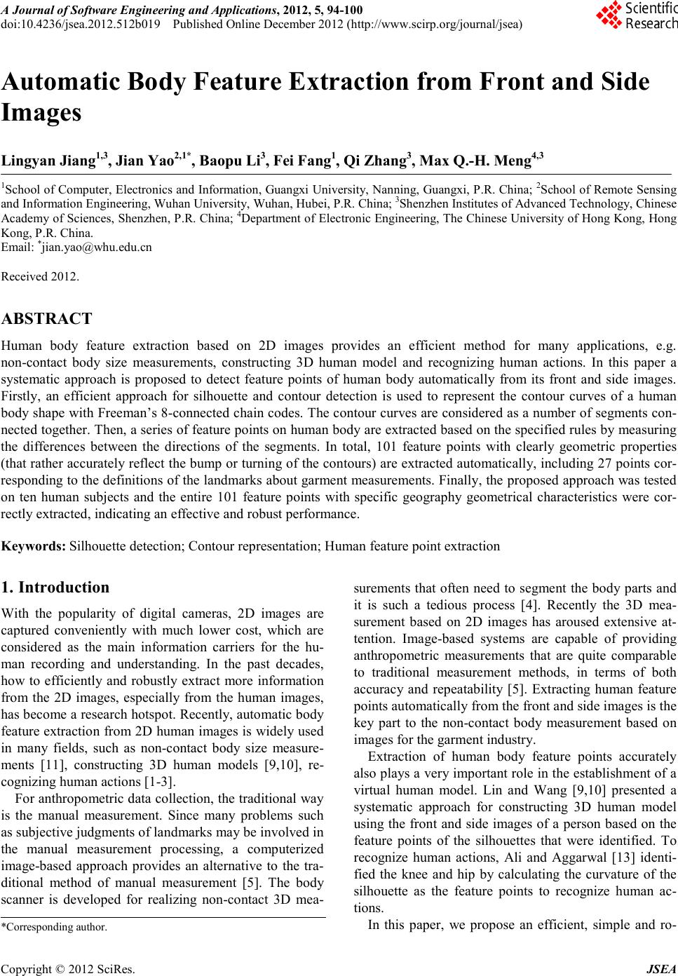
 A Journal of Software Engineering and Applications, 2012, 5, 94-100 doi:10.4236/j s ea.2 012.512b019 Published Online December 2012 (http://www.scirp.org/journal/jsea) Copyright © 2012 SciRes. JSEA Automatic Body Feature Extraction from Front and Side Images Lingyan Jiang1,3, Jian Yao2,1*, Baopu Li3, Fei Fan g 1, Qi Zhang3, Max Q.-H. Meng4,3 1School of Computer, Electronics and Information, Guangxi University, Nanning, Guangxi, P .R. Ch ina; 2School of Remote Sensin g and Information Engineering, Wuhan University, Wuhan, Hubei, P.R. China; 3Shenzhen Institutes of Advanced Technology, Chinese Academy o f Sciences, Shenzhen , P.R. China; 4Department of Electronic Engineering, The Chinese University of Hong Kong, Hong Kong, P.R. China. Email: *jian.yao@whu.edu.cn Received 2012. ABSTRACT Human body feature extraction based on 2D images provides an efficient method for many applications, e.g. non-contact body size measurements, constructing 3D human model and recognizing human actions. In this paper a systematic approach is proposed to detect feature points of human body automatically from its front and side images. Firstly, an efficient approach for silhouette and contour detection is used to represent the contour curves of a human body shape with Freeman’s 8-connected chain codes. The co ntour curves are considered as a number of segments con- nected together. Then, a series of feature points on human body are extracted based on the specified rules by meas uring the differences between the directions of the segments. In total, 101 feature points with clearly geometric properties (that rather acc urately reflect t he bump or turnin g of the co ntours) are extracted automatically, including 27 points cor- resp onding t o the d efini tions o f the land mark s abo ut gar ment mea sureme nts. Fi nall y, the p roposed ap proach was tested on ten human subjects and the entire 101 feature points with specific geography geometrical characteristics were cor- rectly extracted, indicating an effective and robust performance. Keywords: Silhouette detection; Contour representation ; Human feature point extraction 1. Introduction With the popularity of digital cameras, 2D images are captured conveniently with much lower cost, which are considered as the main information carriers for the hu- man recording and understanding. In the past decades, how to efficiently and robustly extract more information from the 2D images, especially from the human images, has become a research hotspot. Recently, automatic body feature extraction fro m 2D human images is widely used in many fields, such as non-contact body size measure- ments [11], constructing 3D human models [9,10], re- cognizin g human actions [1-3]. For anthropo metric d ata collection, the traditio nal way is the manual measurement. Since many problems such as subjective judgments of landmarks may be involved in the manual measurement processing, a computerized image-based approach provides an alternative to the tra- ditional method of manual measurement [5]. The body scanner is developed for realizing non-contact 3D mea- surements that often need to segment the body parts a nd it is such a tedious process [4]. Recently the 3D mea- surement based on 2D images has aroused extensive at- tention. Image-based systems are capable of providing anthropometric measurements that are quite comparable to traditional measurement methods, in terms of both accuracy and repeatability [5]. Extracting human feature points automatically from the fr ont and si de images is the key part to the non-contact body measurement based on images for the garment industry. Extraction of human body feature points accurately also pla ys a very important role in t he establishment o f a virtual human model. Lin and Wang [9,10] presented a systematic approach for constructing 3D human model using the front and side images of a person based on the feature points of the silhouettes that were identified. To recognize human actions, Ali and Aggarwal [13] identi- fied the knee and hip by calculating the curvature of the silhouette as the feature points to recognize human ac- tions. In this paper, we propose an efficient, simple and ro- *Corresponding author.  Automatic Body Feature Extraction from Front and Side Images Copyright © 2012 SciRes. JSEA bust human body feature point detection algor ithm based on the front and side images of a human body, whose key inspiration stems from a series of studies [9-12]. Background subtraction is used to obtain the contours. Canny edge detection operator [8] and Freeman’s 8-connected [6] chain codes are used to represent the silhouette curves. Then the curves are cut into a series of segments whose directions are denoted by the corres- ponding values of second chain codes in the segments. Therefore, specific rules for measuring the differences between the directions of segments are utilized to extract the feature points. The proposed method was tested on ten human subjects and all of the 101 pre-defined feature points were correctly extracted. Among these feature points, there are 27 points with geometrical properties that indicate concavity and convexity of the curves per- fectly, corresponding to the definitions of landmarks related to garme nt measurements. In [11, 12], a total of 55 and 60 feature points can be extracted from front and side images, respectively. Comparing with [11,12], there are more feature points detected in our work. In addition, different methods of contour detection and different feature point extraction rules are used in our approach. Firstly, the used back- ground subtraction is more applicable to complex back- ground than the methods used in [11, 12]. Secondly, the feature points extracted in our work are independent with each other. Howeve r , in [11,12] the feature point always depend on the previous feature point, even both the ad- jacent feature points, so if one point is wrongly detected, the others may be unbelievable. Thirdly, in [11,12], the method to extract the secondary feature points is to use the primary feature points as the auxiliary points to help to locate the new feature points. Our method is more intuitive, since all feature points extracted in the same batch. Finally, the feather points detected in [11,12] had not compared with definitions in any standard, it is not enough to take it as left shoulder acromion or other landmar ks , but it had been done in this paper. 2. Feature Points Extraction 2.1. Photographing and Pre-processing Firstly, the camera is positioned at 5m distance fro m the subjects and 1m height from the gro und and four images are captured, two of the background and two of the hu- man subject. In experiments, the Canon SX130 camera was used to capture the images with a resolution of 4000×3000 pixels and with opening flash to reduce the effects of shadowing. In order to reduce the data processing time, the front and side images are resized into 1260×1854 p ixels and 504×1854 ones which remain the parts of the human body and then are reduced to 211×309 pixels and 84×309 pixels, respectively. At the same time, the corresponding parts of the backgrounds are processed in the same way. (a) (b) (c) (d) Figure 1. The results of a male model after photographing & pre-processing: (a)-( b) The front image and its back- ground; (c)-(d) The side image and its bac kground. Subjects are lightly clothed and also are required to wear a headgear to reduce the influences of hair on the test results. The subjects are requested to stand in front of a white wall with a standing posture. When shooting the human from the frontal view, Legs of the subject are apart from each other for shoulder width and arms open on both sides of the body, while the fingers face to the camera and are forced open. The results of a male model after photographing and pre-processing are shown in Figure 1 (The pictures in this paper all come from our experiment about a male model). 2.2. Silhouette Detection and Contour Representation The used e xtractio n algorithm of the body silhouettes is a standard background subtraction to isolate the subject from ima ges, whos e steps are described as follo ws: 1) Calculating the color difference values of the cur- rent image and the background as follows: [ ][ ] [ ][ ] [ ][ ] - (R) C(G) =- C (B)- ij ij ij ijij ij ij ij ij X RYR C X GYG X BYB (i,j)∈Ω (1) where Ω denotes the fields of images, Xij and Yij represent the RGB color value of the current image pixel (i,j), and the background pixel (i,j), respectively. 2) Differences between foreground and background pixels are measured as follows: ( ) [ ][][ ] 12 3 ,=+C+ ij ij ij Dij d CRdGdCB××× (2) where d1, d2 and d3 are the weighted values of Red, Green and Blue channels, respectively. All of our images were taken under the natural light. Since RGB are basically the same as the natural light, the weighted va lues are set to 1. 3) If D(i,j) is larger than a pre-defined threshold val-  Automatic Body Feature Extraction from Front and Side Images Copyright © 2012 SciRes. JSEA 96 ue , the pixel (i,j) is regarded as a former attractions, and vice versa for background. After that, two binary images of the body shapes can be obtained. In our expe- riments was empiricall y set to 3 5. (a) (b) (c) (d) Figure 2. Silhoue t t es and contours of a human b ody: (a) Silhouette extraction result of the front imag e; (b) Sil- houette extracti on result of the side image; (c) Body contour from the front image of the subject; (d) Body contour from the side image of the subject . As illustrated in Figures 2(a)-(b), silhouettes of the front and side views of the subject are extracted. After extracting the body silhouettes from the 2D images, the Canny edge detector [8] is subse quent ly a pplied to locate the silhouettes of human body from the two binary im- ages. The sin gle-pixel and closed contour curves are ex- tracted as shown in Figures 2(c)-(d). The silhouette points on and are denoted as: (3) where f0 and s0 are the starting points on the left-top of the head on each contour curves, fi and si are the clock- wis e th points from the first points, and and s Chave a total of points and ones respectively. To identify these points automatically, the edge pixels of the body silhouettes are encoded by the Freeman’s 8-connected chain codes [6,7]. With the Freeman chain code, the numbers “0”-“7” are used to represent 45° in- crements in a counterclockwise directions starting from an initial horizontal vector “0”. The body contours are descripted with a series of chain codes of pix- els: , . 2.3. Feature Extraction The contour curves of the body are considered as co n- nections of a series of line segments. A part of line seg- ments on the head of the front curve are sho wn in Figure 3. The first segment a1 connects the first point f0 and the consecutive points with the same code value of “0” in sequence, so it starts from the po int f0 to the point f12. The next segments are the connections of the continuous points are in the s ame direction and the previo us point in the different direc tion, such as a2 starts fro m the point f12 to the point f13. Figure 3. A part of line segments on the head. The freeman code of the second point of the line seg- ment in addition to the starting point is taken as the in- clination of the line segment or its direction. If the incli- nations of the current line segment and the adjacent two segment s satisfy one of the conditions that are shown in Figure 4, then the starting or last point (when it comes the left part of the fro nt huma n silho uette curve ) of the current segment line is considered as the feature point of human body. The c urrent line seg me nt direction is presented using red line with arrow and tha t of t he two segments are adjacent to it are used blue lines with ar- r o ws to p resent. If o ne o f the t wo ad jacent segments is in the 45° clockwise direction a nd the other one must be in the 45° counterclockwise direction of the current seg- ment line. So actually, there are 16 cases that can be used to judge a feature point. (a) (b) (c) (d) (e) (f) (g) (h) Figure 4. Eight cases of the line segment dire c t i ons. Another judgment principle is used while the current line segment is perpendicular to the previous line seg- ment . The starting point of the current segment line is considered as the feature point of human body. All of the judgments principle can be expressed as: (a) (b) (c) (d) (e) (f) (g) (4) where d1, d2 and d3 denote the inclinations of the three adjacent segments. Formulas (4)(a) and (4)(b) corres- pond with conditions shown in Figures 4(b-g), formulas 13 2 5 3 7 2 5 1 2 4 6 1 2 7 2 0  Automatic Body Feature Extraction from Front and Side Images Copyright © 2012 SciRes. JSEA (4)(c) and (4)(d) correspond with the case sho wn in Fig- ure 4(a) and formulas (4)(e) and (4)(f) correspond with the case shown in Figure 4(h). Moreover, another judg- ment principle that the absolute value of d2 subtracts d1 equals to 2 in formula (4)(g) corresponds with the condi- tion of two segments are perpendicular. The testing processes of some points are shown in Figure 5 where the starting point on the left-top of the head is token as the first feature p oint H1. T he di re ctions of a9, a10 and a11 are 0, 7 and 6, respectively. Since the three segments conform to the case shown in Figure 4(h), the first point of a10 is token as the second feature point F1. The re- maining feature points are detected according to the rules. Figure 5 . Feature points F1 and F2 extracted on the h ead. Detailed steps of the algorithm are described as fol- lows (the front silhouett e is taken as an example): 1) Calculating the inclinati ons of the segments. The contour curves are expre ssed wit h the code sequence as: p0, p1, …, p(n-1), and then pk is taken as the code value of the po i nt fk. At the fir st, f0 is inserted into the sequence V. If (0<k<n), fk is inserted into V. In addi- tion to f0, eve r y po int in V happens to be the second point of each segment whose code value can be used to represent direction of the segme nt. 2) The detections of feature points. Z is taken as the sequence of feature points. V: v0, v1, …, v(u-1) represents the sequence of pixels. v0 is inserted into Z as the first feat ure point . The co de value s of the cur rent po int vk and the adjacent points v(k-1), v(k+1), (0<k<u-1) just represent their line segment directions. Then the principles in for- mula (4) are used to judge the feature points. If vk, v(k-1) and v(k+1) conform one of the conditions in formula (4), the one of two endpoints of the segment line that in- cludes the point vk is considered as a feature point to be inserted into the sequence Z. 3. Evaluation The algorithm is demonstrated in Matlab 2009a, the 101 feature points are completely detected from ten objects. It proves that this approach is effective and robust. The feature points on front and side images are shown in Figure 6. The same positions of the feature points de- tected are also marked in the color images, as shown in Figure 7. It is demonstrated that the feature points is ra- ther accurate and reliable by visual inspection. Figure 6. Body feat ure points (marked with red circles) cons i s t ing of 71 front ones and 30 side ones . Figure 7. Body feature poi nt s (marked wi th red ci rcl es) on a male model consisting of 71 front ones and 30 side ones. The test results of ten subjec ts consisting of five males and five fe males are shown in T able 1. Table 1. Test results of the ten subjects. 1 3 F6 8 10 12 13 F15 17 19 F18F16F14 22 1 R 5 20 R12 19 14 16 18 R22 23 29 32 35 27 32 35 1 2 7 8 13 23 28 29 1 2 3 F6 10 12 F13 15 F17 19 F18F16F14 22 1 R3 R5 8 20 10 7 R12 13 14 16 18 22 28 29 32 F35 24 27 34 R35 1 3 5 S6 10 11 S13 14 17 18 19 S20 S21 25 24 26 28 29 30 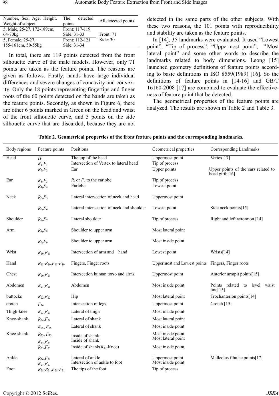 Automatic Body Feature Extraction from Front and Side Images Copyright © 2012 SciRes. JSEA 98 Number, Sex, Age, Height, Weigh t of sub ject All detected points 5, Male , 25-27, 172-189cm, 64-70kg Front: 117-119 Side: 31-33 Front: 71 Side: 30 5, Female, 25-27, 155-161cm, 50 -55kg Front: 112-121 Sid e: 31-34 In total, there are 119 points detected from the front silhouette curve of the male models. However, only 71 points are taken as the feature points. The reasons are given as follows. Firstly, hands have large individual differ ence s and se vere c hange s of conc avit y and co nvex- ity. Only the 18 points representing fingertips and finger roots of the 60 points detected on the hands are taken as the feature points. Secondly, as shown in Fi gure 6, there are other 6 points ma rked in Green on the head and waist of the front silhouette curve, and 3 points on the side silhouette curve that are discarded, because they are not detected in the same parts of the other subjects. With these two reasons, the 101 points with reproducibility and st ability are taken as the feature points. In [14], 35 land marks were evaluated. It used “Lowest point”, “Tip of process”, “Uppermost point”, “Most lateral point” and some other words to describe the landmarks related to body dimensions. Leong [15] launched geometry definitions of feature points accord- ing to basic definitions in ISO 8559(1989) [16]. So the definitions of feature points in [14-16] and GB/T 16160-2008 [17] are combined to evaluate the ef fective- ness of feature point that be detec ted. The geometrical properties of the feature points are analyzed. The results are shown in Table 2 and Table 3. Table 2. Geometrical p roperties of the front feature points and the corresponding lan dmarks. Body regions Feature points Positions Geom etrical properties Corresponding Landmarks 1 1 1 Intersection of Vertex to lateral head 2 2 Upper points of the ears related to head girth[16] 3 3 2 2 4 4 5 5 Lateral intersectio n of neck and he a d 6 6 Lateral intersection of neck an d s ho ulde r 7 7 Right and left acromion [14] 8 8 9 9 10 10 Intersection of arm and hand 11 19 11 19 Uppermost an d Lowest poi nts 20 20 Intersection human torso and arm s Anterior armpit points[15] 21 21 Points relat ed to level waist line[15] 22 22 Tr och ante rion points[14] 36 23 23 24 24 25 25 33 33 Inside of shank Inside of shank Most lateral point 34 34 35 35 33 26 26 R27,F27 Intersection of ank le to foot Most inside point Malleolus fibulae points[17] 28 31 28 31 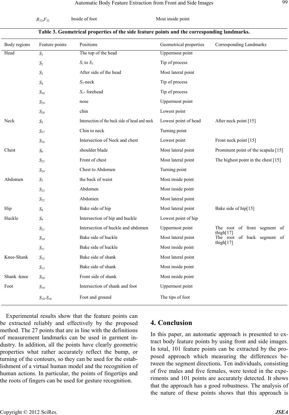 Automatic Body Feature Extraction from Front and Side Images Copyright © 2012 SciRes. JSEA 32 32 Table 3. Geometrical p roperties of the side feature points and the corresponding landmarks. Body regions Feature points Positions Geometrical properti es Corresponding Landma rks 1 2 1 3 3 4 3 30 1 29 28 5 Intersection of the back side of head and neck 27 26 Intersection of Neck and chest Fro nt ne c k po int [15] 6 Prominent point of the scapula [15] 25 The highest point in the chest [15] 24 7 23 22 8 9 Intersection of hip and huckle 21 Intersection of huckle and abdomen The root of front segment of thigh[17] 10 The root of back segment of thigh[17] 11 12 13 20 19 Inters ect ion of shank and f oot 14 18 Experimental results show that the feature points can be extracted reliably and effectively by the proposed met ho d. The 27 points that are in li ne with the definitions of measurement landmarks can be used in garment in- dustry. In addition, all the points have clearly geometric properties what rather accurately reflect the bump, or turni n g o f the c o ntours , so the y can be used for the estab- lishment of a virtual huma n model a nd the recognition of human actions. In particular, the points of fingertips and the roots of fingers can be used for gesture recognition. 4. Conclusion In this paper, an automatic approach is presented to ex- tract body feature points by using front and side images. In total, 101 feature points can be extracted by the pro- posed approach which measuring the differences be- twee n t he seg ment dir ectio ns. Ten i nd ividua ls, consisting of five males and five females, were tested in the expe- riments and 101 points are accurately detected. It shows that the approach has a good robustness. The analysis of the nature of these points shows that this approach is  Automatic Body Feature Extraction from Front and Side Images Copyright © 2011 SciRes. JSEA 100 reliable and effective. All the point s have c learl y geome- tric properties that can be used in many fields. Further- more, by comparing the proposed method with the pre- vious researches, it demonstrates the improved perfor- mance in feature points extraction. In future work, we will focus on collecting the human dimensions, as well as the establishment o f three-dimensional human models based on these extracted feature points. REFERENCES [1] S.A. Rahman, S.-Y. Cho and M.K.H. Leung, “Recognis- ing human actions by analyzing negative spaces,” IET Computer Vision, Vol. 6, No. 3, 2012, pp. 197–213. doi: 10.1049/iet-cvi.2011.0185 [2] N. Ikizler and D.A. Forsyth, “Searching for complex hu- man activities with no visual examples,” Int. Journal of Comput. Visio n , Vol. 80, No . 3, 2008, pp. 337–357. doi: 10.10 07/s11263-008-0142-8 [3] C. Bregler, “Learning and recognizing human dynamics in video Sequences,” Proc. Computer Vision and Pattern Recognition, San Juan, 1997, pp. 568–574. [4] J.M. Lu an d M. J. Wang, “Automated data collect ion usin g 3D whole body s canner, ” Expert Systems with Applica- tions, Vol. 35, No. 1-2, 2008, pp. 407–414. doi: 10.1016/j.eswa.2007.07.008 [5] P. M eunier and S. Yin, “Per formance of a 2D i mage-based anthropometric measurement and clothing sizing system,” Applied Ergonomics, Vol. 31, No . 5, 2000, pp. 445–451. doi:10.1016/S0003-6870(00)00023-5 [6] H. Freeman, “On the en coding of arbitr ary geomet ric con- figuration,” IRE Transactions on Electronics Computers, Vol. EC-10, No. 2, 1961, pp. 264–268. doi:10.1109/TEC.1961.5219197 [7] H. Freeman and L.S. Davis, “A corner-finding algorithm for chain-coded curves,” IEEE Transactions on Comput- ers, Vol. C-26, No. 3, 1977, pp. 297–303. doi:10.1109/TC.1977.1674825 [8] J. Canny, “A computational approach to edge detection,” IEEE Transactions on Pattern Analysis and Machine In- telligence, Vol. 8, No. 6, 1986, pp. 679-698. doi:10.1109/TPAMI.1986.4767851 [9] Y.L. Lin and M.J. Wang, “Constructing 3D Human Model from 2D images,” Int. Conf. on Industrial Engineering and Engineering Management, Xiamen, Oct, 2010, pp.1902-1906. [10] Y.L. Lin and M.J. Wang , “Constructing 3D human model from front and side images,” Expert Systems with Applica- tions, Vol. 39, No. 5, April 2012, pp. 5012–5018. doi:10.1016/j.eswa.2011.10.011 [11] Y.L. Lin and M.J. Wang, “Automatic Feature Extraction from Front and S ide Images,” Int. Conf. on Industrial En- gin eering and Engineering Management, Singapore, Dec, 2008, pp. 1949-1953. [12] Y.L. Lin and M.J. Wang , “Automated body feature ex- traction from 2D images,” Expert Systems with Applica- tions, Vol. 38, No. 3, 2011, pp. 2585–2591. doi:10.1016/j.eswa.2010.08.048 [13] A. Ali and J. K. Aggarwal, “Segmentation and recognition of continuous human activity,” Proc. IEEE Workshop on Detection & Reco g. of Events in Video, Vancouver, BC, 2001, pp. 28–35. [14] M. Kouchi and M. Mochimaru, “Errors in landmarking and the evaluation of the accuracy of traditional and 3D anthropometry,” Applied Ergonomics, Vol. 42, No. 3, 2011, pp. 518-527. doi:10.1016/j.eswa.2010.08.048 [15] Iat-Fai Leong, “A study of automatic anthropometry and construction of computer manikins,” Master's thesis of National Cheng Kung University, 1992. (In Chinese) [16] ISO8559-1989 garment construction and anthropometric surveys body dimensions. [17] GB/T16160-2008 location and method of anthropometric surveys for garment.
|