Paper Menu >>
Journal Menu >>
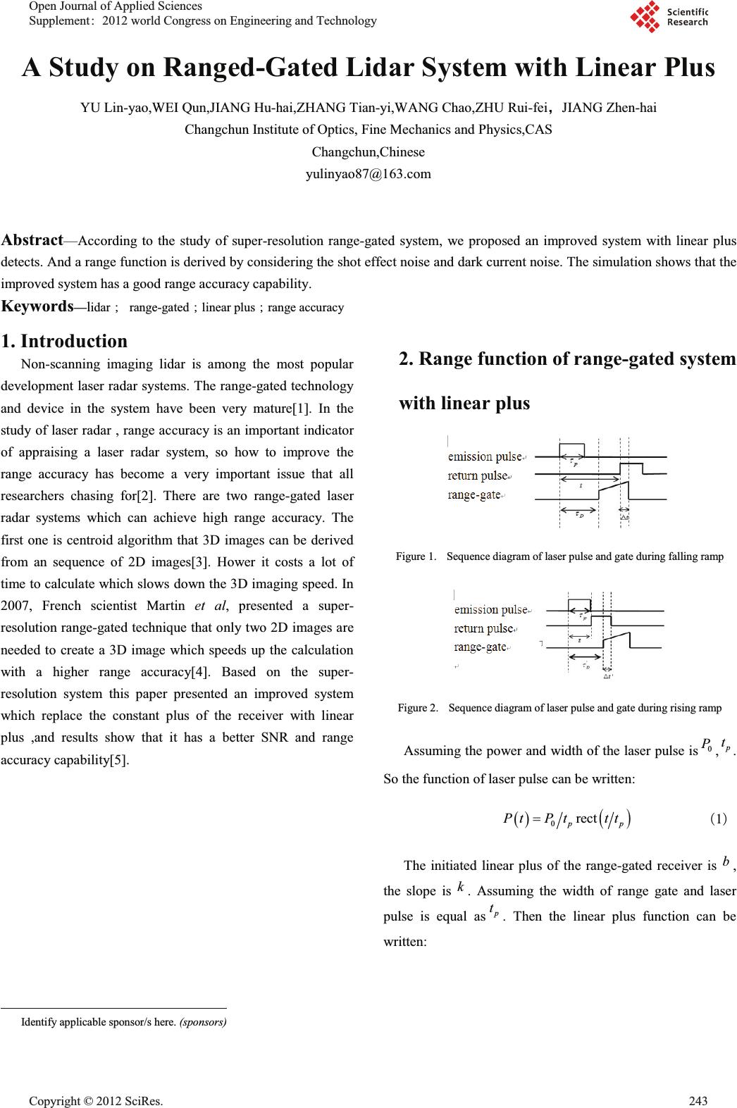 A Study on Ranged-Gated Lidar System with Linear Plus YU Lin-yao,WEI Qun,JIANG Hu-hai,ZHANG Tian-yi,WANG Chao,ZHU Rui-feiθJIANG Zhen-hai Changchun Institute of Optics, Fine Mechanics and Physics,CAS Changchun,Chinese yulinyao87@163.com Abstract—According to the study of super-resolution range-gated system, we proposed an improved system with linear plus detects. And a range function is derived by considering the shot effect noise and dark current noise. The simulation shows that the improved system has a good range accuracy capability. Keywords—lidar㸹range-gated㸹linear plus㸹range accuracy 1. Introduction Non-scanning imaging lidar is among the most popular development laser radar systems. The range-gated technology and device in the system have been very mature[1]. In the study of laser radar , range accuracy is an important indicator of appraising a laser radar system, so how to improve the range accuracy has become a very important issue that all researchers chasing for[2]. There are two range-gated laser radar systems which can achieve high range accuracy. The first one is centroid algorithm that 3D images can be derived from an sequence of 2D images[3]. Hower it costs a lot of time to calculate which slows down the 3D imaging speed. In 2007, French scientist Martin et al, presented a super- resolution range-gated technique that only two 2D images are needed to create a 3D image which speeds up the calculation with a higher range accuracy[4]. Based on the super- resolution system this paper presented an improved system which replace the constant plus of the receiver with linear plus ,and results show that it has a better SNR and range accuracy capability[5]. 2. Range function of range-gated system with linear plus Figure 1. Sequence diagram of laser pulse and gate during falling ramp Figure 2. Sequence diagram of laser pulse and gate during rising ramp Assuming the power and width of the laser pulse is0 P, p t . So the function of laser pulse can be written: 0 rect pp PtP ttt 㸦1㸧 The initiated linear plus of the range-gated receiver is b , the slope is k . Assuming the width of range gate and laser pulse is equal as p t . Then the linear plus function can be written: Identify applicable sponsor/s here. (sponsors) Open Journal of Applied Sciences Supplement:2012 world Congress on Engineering and Technology Cop y ri g ht © 2012 SciRes.243  1rect p Gtkt btt 㸦2㸧 There are two intensities of images to calculate. Firstly, we derive the intensity when only the front part of the pulse received by the range gate, the Sequence diagram of laser pulse and gate during falling ramp is shown in figure 1. The distance between the target and the detector isz, and the time that the laser pulse travels is2tzc . The delay time between the pulse starting transmitting and the range gate getting open is D W . The width of the pulse which received by range gate when it is open can be written: 2 Dp Dp z tt c WW WW ' 㸦3㸧 The intensity of the image is: 11 p p t tt IR dtPtGt ' ³ 㸦4㸧 We can get another intensity function in the same way, the delay time is ' DDp WWW . The Sequence diagram of the pulse and gate during falling ramp is shown in figure 2. The width of the pulse which received by range gate is: '' 2 pD D z tttc WW ' 㸦5㸧 The intensity function can be written: ' 21 0 t IRdtPtGt ' ³ 㸦6㸧 From equation (1)~(7),we can get the range function: 22 2 2 21 pp p p Dp Mkt bt kt b kt b c zt kkM k W §· ¨¸ ¨¸ ¨¸ ©¹ 㸦7㸧 While M is: 22 2 1 22 2 2 2 2 22 p D p pp D kt bzb ck k I MIkt b kt btzb kck k W W ªº §· «» ¨¸ «» ©¹ ¬¼ ªº §· §· «» ¨¸ ¨¸ ¨¸ «» ©¹ ©¹ ¬¼ 㸦8㸧 3. SNR and range accuracy The differential coefficient of equation (9) can be written: 12 12 p dI dI dzAABdtCdk Ddb II 㸦9㸧 Then the range accuracy of the system is: 2 222 22 12 22 22 11 2 p AABt cSNR SNR z Ck Db G G GG 㸦10㸧 We only consider the first and second term approximately as the affection of other terms is small. Then the range accuracy of the linear plus system can be written: 2 22 2 22 2 12 2 42 1 11 1 pp pp p kt bt c z Mkt bt kt b kkM k M SNR SNR M G u 㸦11㸧 If the shot effect noise and dark current noise are independent, then the total noise of the system can be presented as: 222 2 alliccd sd di iccd FG It FNG e VVV 㸦12㸧 While iccd F is noise factor (usually is 2 ), N is the number of photoelectrons, G is the plus of the system, d I is the dark current of ICCD,i tis the integral time of ICCD, e is the charge of an electronic. Then the SNR of the system can be written: 2 2 out all di iccd pc r t pc di iccd r t NN SNR GIt FN e Gptdt w GIt FG ptdt we V K K ³ ³ 㸦13㸧 244 Cop y ri g ht © 2012 SciRes. 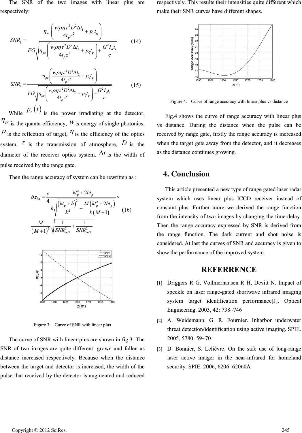 The SNR of the two images with linear plus are respectively: 22 10 2 12 22 10 2 4 4 pc g p di pc g p wDt pt tz SNR GIt wDt FGp t tz e UKW K UKW K §· ' ¨¸ ¨¸ ©¹ §· ' ¨¸ ¨¸ ©¹ 㸦14㸧 22 20 2 22 22 20 2 4 4 pc g p di pc g p wDt pt tz SNR GIt wDt FGp t tz e UKW K UKW K §· ' ¨¸ ¨¸ ©¹ §· ' ¨¸ ¨¸ ©¹ 㸦15㸧 While r pt is the power irradiating at the detector, pc K is the quanta efficiency, w is energy of single photonics, U is the reflection of target, K is the efficiency of the optics system, W is the transmission of atmosphere, D is the diameter of the receiver optics system. t' is the width of pulse received by the range gate. Then the range accuracy of system can be rewritten as : 2 22 2 22 2 12 2 42 1 11 1 pp lin pp p out out kt bt c z Mkt bt kt b kkM k M SNR SNR M G u (16) Figure 3. Curve of SNR with linear plus The curve of SNR with linear plus are shown in fig 3. The SNR of two images are quite different: grown and fallen as distance increased respectively. Because when the distance between the target and detector is increased, the width of the pulse that received by the detector is augmented and reduced respectively. This results their intensities quite different which make their SNR curves have different shapes. Figure 4. Curve of range accuracy with linear plus vs distance Fig.4 shows the curve of range accuracy with linear plus vs distance. During the distance when the pulse can be received by range gate, firstly the range accuracy is increased when the target gets away from the detector, and it decreases as the distance continues growing. 4. Conclusion This article presented a new type of range gated laser radar system which uses linear plus ICCD receiver instead of constant plus. Further more we derived the range function from the intensity of two images by changing the time-delay. Then the range accuracy expressed by SNR is derived from the range function. The dark current and shot noise is considered. At last the curves of SNR and accuracy is given to show the performance of the improved system. REFERRENCE [1] Driggers R G, Vollmerhausen R H, Devitt N. Impact of speckle on laser range-gated shortwave infrared imaging system target identification performance[J].Optical Engineering. 2003, 42: 738~746 [2] A. Weidemann, G. R. Fournier. Inharbor underwater threat detection/identification using active imaging. SPIE. 2005, 5780: 59~70 [3] D. Bonnier, S. Lelièvre.On the safe use oflong-range laser active imager in the near-infrared for homeland security. SPIE. 2006, 6206: 62060A Cop y ri g ht © 2012 SciRes.245  [4] Jens Busck, Henning Heiselberg. Gatedviewing and high-accuracythree-dimensional laser radar. Applied Optics. 2004, 43(24): 4705~4710 [5] Martin Laurenzis, Frank Christnacher. Long-rangethree- dimensional active imaging with superresolution depth mapping. Optics Letter. 2007, 32(21): 3146~3148. 246 Cop y ri g ht © 2012 SciRes. |