Paper Menu >>
Journal Menu >>
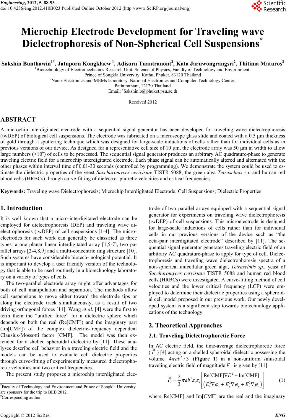 Engineering, 2012, 5, 88-93 doi:10.4236/eng.2012.410B023 Published Online October 2012 (http://www.SciRP.org/journal/eng) Copyright © 2012 SciRes. ENG Microchip Electrode Development for Traveling wave Dielectrophoresis of Non-Spherical Cell Suspensi on s* Sakshin Bunthawin1#, Jatuporn Kongklaew 1, Adisor n Tuantr anont2, Kata Jaruwongrangsri2, Thitima Maturos2 1Bi o tech nology o f Electromechan ics Res earc h Unit, Science of Physics, Faculty of Technology and Environment, Prin ce of Songk la Universit y, Kathu, P huke t, 83120 Tha ilan d 2Nano-Electronic s and MEMs lab oratory, Na tiona l E lec tronic s and Computer T echn ology Center, Pathumthani , 12120 Thai land Email: #Sakshin.b@phuket.psu.ac.th Received 2012 ABSTRACT A microchip interdigitated electrode with a sequential signal generator has been developed for traveling wave dielectrophoresis (twDEP ) of biological cell suspensi ons. The el ectrod e was fabricated on a microsco pe glass sli de and coated with a 0.5 μm thickness of gold through a sputtering technique which was designed for large-scale inductions of cells rather than for individual cells as in previous versions of our device. As designed for a representative cell size of 10 μm, the electrode array was 50 μm in width to allow large nu mbers (>1 06) o f cells t o be p ro cessed . The seq u ent ial si gnal gener ato r pr odu ces an arbitr ary AC qu adrat ur e-ph ase to gen erate travelin g electri c field for a microch ip interd igi tated elect rode. Each phase si gnal can b e au to matical ly alter ed an d alter nat ed with the other phases within interval time of 0.01-30 seconds (controlled by programming). We demonstrate the system could be used to es- timate the dielectric properties of the yeast Saccharomyces cerivisiae TISTR 5088, the green alga Tetraselmis sp. and human red blood cells (HRBCs) through curve-fitting of dielectro- phor etic velociti es and critical frequencies. Keywords: Traveling wave Dielectrophoresis; Microchip Interdigitated Electrode; Cell Suspensions; Dielectric Properties 1. Introduction It is well known that a micro-interdigitated electrode can be employed for dielectrophoresis (DEP) and traveling wave di- electrophoresis (twDEP) of cell suspensions [1-4]. The micro- electrodes for such work can generally be classified as three types: a one planar linear interdigitated array [1,5-7], two pa- rallel arra ys [2 -4 ,8, 9] and a mu lt i-co n cent ric ri ng st ructure [10] . Such systems have considerable biotech- nological potential. It is important to develop a user friendly version of the technolo- gy that is able to be used routinely in a biotechnology laborato- ry on a variety of types of cells. The two-parallel electrode array might offer advantages for both of cell manipulation and separation. The methods allow cell suspensions to move either toward the electrode tips or along the electrode track simultaneously, as a result of two driving orthogonal forces [11]. Wang et al. [ 4] were the first to term them the “unified force” for a dielectric sphere which depends on both the real (Re[CMF]) and the imaginary part (Im[CMF]) of the complex dielectric-frequency dependent Clausius-Mossotti factor [CMF]. The model was then ex- tended for a shelled spheroidal dielectric by [11]. These ana- lyses describe cell behavior in a traveling electric field and the models can be used to evaluate cell dielectric properties through curve-fitting of experimentally measured dielectropho- retic velo cities an d two critical frequencies. The present study proposes a microchip interdigitated elec- trode of two parallel arrays equipped with a sequential signal generator for experiments on traveling wave dielectrophoresis (twDEP) of cell suspensions. This microelectrode is designed for large-scale inductions of cells rather than for individual cells in our previous versions of the device such as “the octa-pair interdigitated electrode” described by [11]. The se- quen tial signal generato r generates traveli ng electric field o f an arbitrary AC quadrature-phase to apply for t ype of cell. Dielec- trophoresis and traveling wave dielectrophoresis spectra of a non-spherical unicellular green alga, Tetraselmis sp ., yeast of Saccharomyces cervisiate TISTR 5088 and human red blood cells (HRBCs) wer e investigated. A curve-fitting method of cell velocities and the lower critical frequency (LCF) were em- ployed to determine their dielectric properties using a spheroid- al cell model proposed in our previous work. Our newl y dev el- oped system is a significant step towards biotechnology appli- cations of the technology. 2. Theoretical Approaches 2.1. Traveling Dielectrophoretic Force In AC electric field, the time-average dielectrophoretic force (t F ) [4] actin g on a shel led sph eroidal diel ectric pos sessing th e volume 2 4 /3ab π (Figure 1) in a non-uniform sinusoidal traveling electric field of magnitude E is given by [11] ( ) 2 20222 Re[CMF] Im[CMF] 2 3 ts xx yy zz E F abEEE π εεϕϕϕ ∇+ = ∇+∇+∇ (1) where Re[CMF] and Im[CMF] are the real and the imaginary *Facult y of Techn ology and En vironmen t and Prin ce of Songkla Un ive r sity are spon so r s f or the trip to BEB 2012. #Corresponding author. 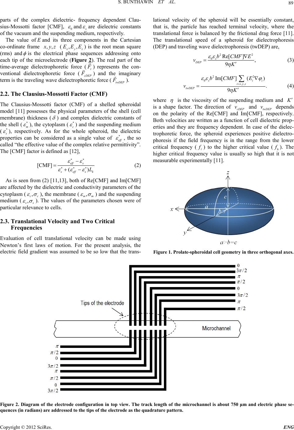 S. BUNTHAWIN ET AL. Copyright © 2012 SciRes. E NG 89 parts of the complex dielectric- frequency dependent Clau- sius-Mossotti factor [CMF], 0 ε and s ε are dielectric constants of the vacuum and the suspending medium, resp ectively. The value of E and its three components in the Cartesian co-ordinate frame ,,xyz ( ,, xyz EEE ) is the root mean square (rms) and φ is the electrical phase sequences addressing onto each tip of the microelectrode (Figure 2). The real part of the time-average dielectrophoretic force ( t F ) represents the con- ventional dielectrophoretic force ( cDEP F ) and the imaginary term is the traveling wave dielectrophoretic force (twDEP F ). 2.2. The Clausius-Mossotti Factor (CMF) The Clausius-Mossotti factor (CMF) of a shelled spheroidal model [11] possesses the physical parameters of the shell (cell me mbr a ne) thickness ( δ ) and complex dielectric constants of the shell (* m ε ), th e cytopl asm (* c ε ) and the suspending medium ( * s ε ), respectively. As for the whole spheroid, the dielectric properties can be considered as a single value of * eff ε , the so called “t he effecti ve value of the complex relative permittivity”. The [CMF] factor is defined as [ 12], [CMF] () eff s seffs k L εε εεε ∗∗ ∗∗∗ − =+− (2) As is seen from (2) [11,13], both of Re[CMF] and Im[CMF] are affected b y the d ielect ric an d con duct ivit y paramet ers o f the cytoplasm ( , cc εσ ), the membrane ( , mm εσ ) and the suspending medium ( , ss εσ ). The values of the parameters chosen were of particular rel evance to cel ls. 2.3. Translational Ve locity and Two Crit ic al Frequencies Evaluation of cell translational velocity can be made using Newton’s first laws of motion. For the present analysis, the electric field gradient was assumed to be so low that the trans- lational velocity of the spheroid will be essentially constant, that is, the particle has reached terminal velocity, where the translational force is balanced by the frictional drag force [11]. The translational speed of a spheroid for dielectrophoresis (DEP) and traveling wave dielectro phoresi s (twDEP) are, 22 0 Re[] , 9 s DEP bCMF E vK εε η ∇ =′ (3) 22 0,, Im[] () . 9 s ii i xyz twDEP b CMFE vK εε ϕ η = ∇ =′ ∑ (4) where η is the viscosity of the suspending medium and K′ is a shape factor. The direction of cDEP v and twDEP v depends on the polarity of the Re[CMF] and Im[CMF], respectively. Both velocit ies are written as a fu nction of cell diel ectric prop- erties and they are frequency dependent. In case of the dielec- trophoretic force, the spheroid experiences positive dielectro- phoresis if the field frequency is in the range from the lower critical frequency ( f ) to the higher critical value ( h f ). The higher critical frequency value is usually so high that it is not measurabl e experi ment ally [11]. Figu re 1. Pro late-spheroidal cell geometry in three orthogonal axes. Figure 2. Diagram of the electrode configuration in top view. The track length of the microchannel is about 750 μm and electric phase se- quences (in radians ) are addressed to the tips of the electrode as the quadrature pattern. 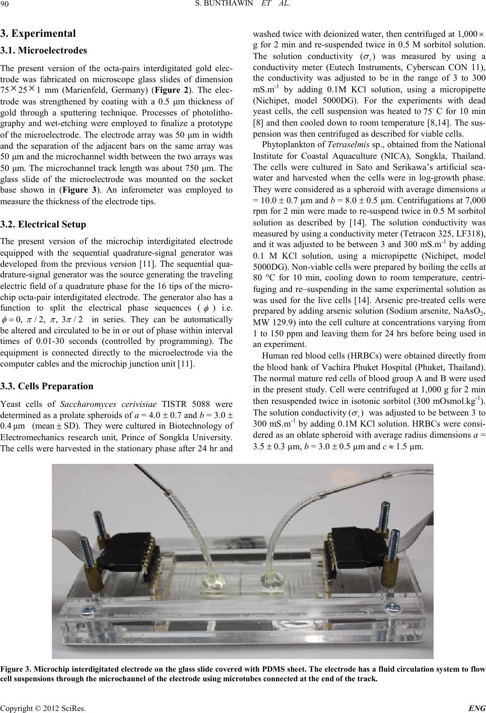 S. BUNTHAWIN ET AL. Copyright © 2012 SciRes. ENG 90 3. Experimental 3.1. Microelectrodes The present version of the octa-pairs interdigitated gold elec- trode was fabricated on microscope glass slides of dimension 75 × 25 × 1 mm (Marienfeld, Germany) (Figur e 2). The elec- trode was strengthened by coating with a 0.5 μm thickness of gold through a sputtering technique. Processes of photolitho- graphy and wet-etching were employed to finalize a prototype of the microelectrode. The electrode array was 50 μm in width and the separation of the adjacent bars on the same array was 50 μm and the microchannel width between the two arrays was 50 μm. The microchannel track length was about 750 μm. The glass slide of the microelectrode was mounted on the socket base shown in (Figure 3). An inferometer was employed to measure th e thickn ess of the elect r ode tip s . 3.2. Electrical Setup The present version of the microchip interdigitated electrode equipped with the sequential quadrature-signal generator was developed from the previous version [11]. The sequential qua- drature-signal generato r was the so urce gen erating t he traveling electric field of a qu adrature ph ase for the 16 tips of the micro- chip octa-pair interd igitated electrod e. The generator also h as a function to split the electrical phase sequences ( φ ) i.e. 0,/ 2,,3/ 2 φπ ππ = in series. They can be automatically be altered and circulated to be in or out of phase within interval times of 0.01-30 seconds (controlled by programming). The equipment is connected directly to the microelectrode via the computer cables and the microchip junction unit [11]. 3.3. Cells Preparation Yeast cells of Saccharomyces cerivisiae TISTR 5088 were determined as a prolate spheroids of a = 4.0 ± 0.7 and b = 3.0 ± 0.4 μm (mean ± SD). They were cultured in Biotechnology of Electromechanics research unit, Prince of Songkla University. The cells were h arvested i n the station ary phase after 24 h r and washed twice with deionized water, then centrifuged at 1,000 × g for 2 min and re-suspended twice in 0.5 M sorbitol solution. The solution conductivity () s σ was measured by using a conductivity meter (Eutech Instruments, Cyberscan CON 11), the conductivity was adjusted to be in the range of 3 to 300 mS.m-1 by adding 0.1M KCl solution, using a micropipette (Nichipet, model 5000DG). For the experiments with dead yeast cells, the cell suspension was heated to75C for 10 min [8] and then cooled down to room temperature [8,14]. The sus- pensi on was then centrifuged as described for viab le cells. Phytoplankton of Tetraselmis sp., obtained from the National Institute for Coastal Aquaculture (NICA), Songkla, Thailand. The cells were cultured in Sato and Serikawa’s artificial sea- water and harvested when the cells were in log-growth phase. They were considered as a spheroid with average dimensions a = 10.0 ± 0.7 µm and b = 8.0 ± 0.5 µm. Centrifugations at 7,000 rpm for 2 min were made to re-suspend twice in 0.5 M sorbitol solution as described by [14]. The solution conductivity was measured by using a conductivity meter (Tetracon 325, LF318 ), and it was adjusted to be between 3 and 300 mS.m-1 by adding 0.1 M KCl solution, using a micropipette (Nichipet, model 5000DG). Non-viable cells were prep ared by boiling the cells at 80 °C for 10 min, cooling down to room temperature, centri- fuging and re–suspending in the same experimental solution as was used for the live cells [14]. Arsenic pre-treated cells were prepared by adding arsenic solution (Sodium arsenite, NaAsO2, MW 129.9) into the cell culture at concentrations varying from 1 to 150 ppm and leaving them for 24 hrs before being used in an experi ment. Human red b lood cells (HR BCs) were ob tained direct ly from the blood bank of Vachira Phuket Hospital (Phuket, Thailand). The normal mature red cells of blood group A and B were used in the present study. Cell were centrifuged at 1,000 g for 2 min then resuspended twice in isotonic sorbitol (300 mOsmol.kg-1). The solution conductivity () s σ was adjusted to be between 3 to 300 mS.m-1 by adding 0.1M KCl solution. HRBCs were consi- dered as an oblate spheroid with average radius dimensions a = 3.5 ± 0.3 µm, b = 3.0 ± 0.5 µm and c ≈ 1.5 µm. Figure 3. Microchip interdigitated electrode on the glass slide covered with PDMS sheet. The electrode has a fluid circulation system to flow cell suspe nsions through the microchannel of the electro de using microtubes connected at the end of the track. 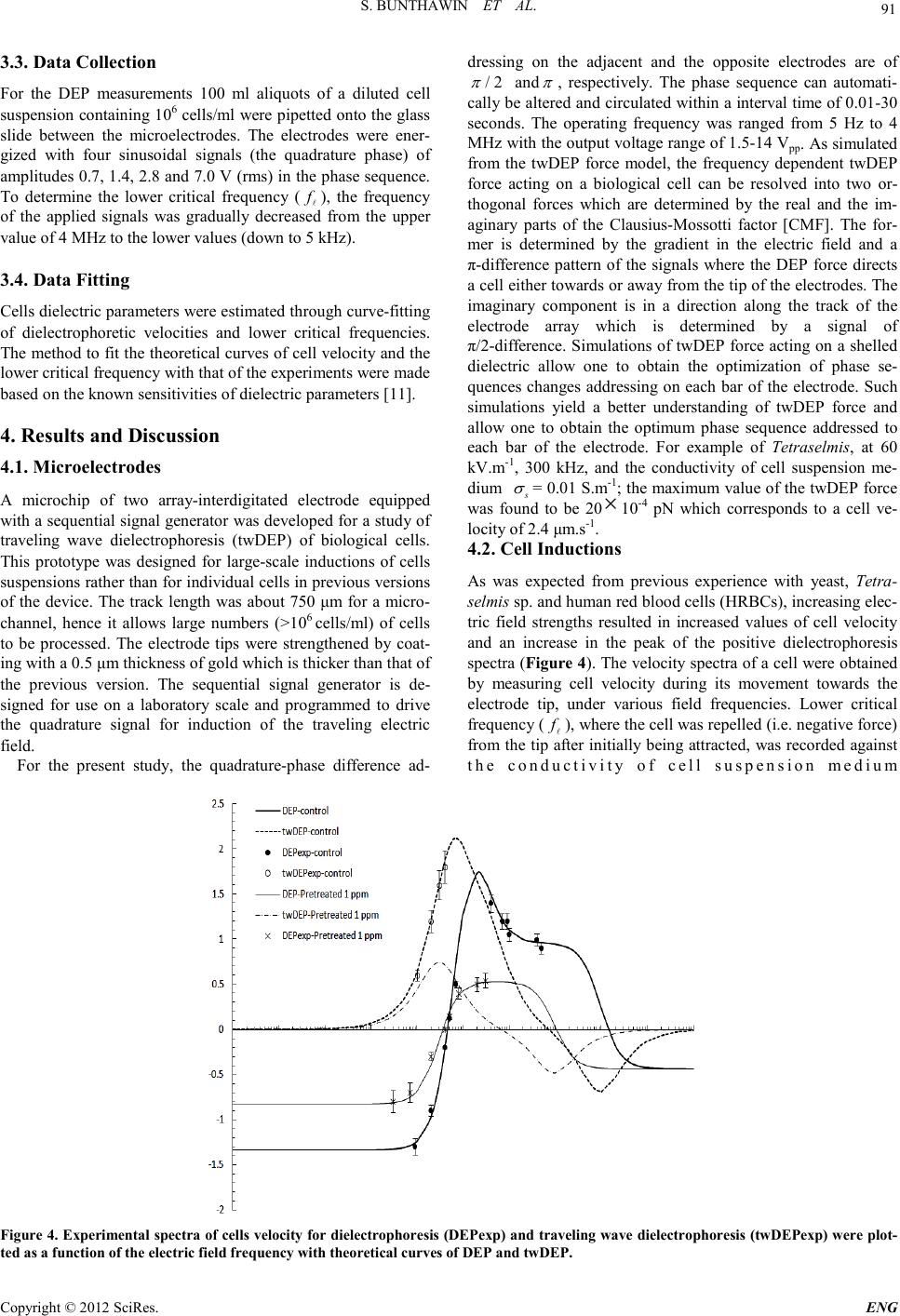 S. BUNTHAWIN ET AL. Copyright © 2012 SciRes. E NG 91 3.3. Data Collectio n For the DEP measurements 100 ml aliquots of a diluted cell suspension containing 106 cells/ml were pipetted onto the glass slide between the microelectrodes. The electrodes were ener- gized with four sinusoidal signals (the quadrature phase) of amplitudes 0.7, 1.4, 2.8 and 7.0 V (rms) in the phase sequence. To determine the lower critical frequency ( f ), the frequency of the applied signals was gradually decreased from the upper value of 4 MHz to the lower values (down to 5 kHz). 3.4. Data Fitting Cells d ielect ric p ara meters wer e e stimat ed t hr ou gh curve-fitting of dielectrophoretic velocities and lower critical frequencies. The metho d to fit th e theoretical curves of cell velocity and the lower critical frequency with that of the experiments were made based on the known sensitivities of dielectric parameters [11]. 4. Results and Discussion 4.1. Microelectrodes A microchip of two array-interdigitated electrode equipped with a sequent ial signal gen erator was developed for a stud y of traveling wave dielectrophoresis (twDEP) of biological cells. This prototype was designed for large-scale inductions of cells suspensions rather than for individual cells in previous versions of the device. The track length was about 750 μm for a micro- channel, hence it allows large numbers (>106 cells/ml) of cells to be processed. The electrode tips were strengthened by coat- ing with a 0.5 μm thickness of gold which is thicker than that of the previous version. The sequential signal generator is de- signed for use on a laboratory scale and programmed to drive the quadrature signal for induction of the traveling electric field. For the present study, the quadrature-phase difference ad- dressing on the adjacent and the opposite electrodes are of /2 π and π , respectively. The phase sequence can automati- cally be alt ered and ci rculated wit hin a interval time of 0.01-30 seconds. The operating frequency was ranged from 5 Hz to 4 MHz with the output voltage range o f 1.5-14 Vpp. As simulated fro m the twDEP force model, the frequency dependent twDEP force acting on a biological cell can be resolved into two or- thogonal forces which are determined by the real and the im- aginary parts of the Clausius-Mossotti factor [CMF]. The for- mer is determined by the gradient in the electric field and a π-difference pattern of the signals where the DEP force directs a cell eith er towards o r away from the tip of the electr odes. The imaginary component is in a direction along the track of the electrode array which is determined by a signal of π/2-difference. Simulations of twDE P force acting o n a shelled dielectric allow one to obtain the optimization of phase se- quences changes addressing on each bar of the electrode. Such si mul ations yield a better understanding of twDEP force and allow one to obtain the optimum phase sequence addressed to each bar of the electrode. For example of Tetraselmis, at 60 kV. m-1, 300 kHz, and the conductivity of cell suspension me- dium s σ = 0.0 1 S.m-1; the maximum valu e of the twDEP force was found to be 20 × 10-4 pN which corresponds to a cell ve- locity of 2.4 μm.s-1. 4.2. Cell Inductions As was expected from previous experience with yeast, Tetra- selmis sp. and human red blood cells (HRBCs), increasing elec- tric field strengths resulted in increased values of cell velocity and an increase in the peak of the positive dielectrophoresis spectra (Figure 4). The velo city spectra of a cell were obtained by measuring cell velocity during its movement towards the electrode tip, under various field frequencies. Lower critical frequency ( f ), wh e re th e cell was repel led (i.e. negative force) from the tip after initially being attracted, was recorded against the conductivity of cell suspension medium Fig ure 4. Experi mental spec tra of cell s veloc ity fo r diel ectro phores is (DEP exp) a nd tra veli ng wave dielectrophoresis (twDEPexp) were plot- ted as a function of the electric field frequency with theoretical curves of DEP and twDEP.  S. BUNTHAWIN ET AL. Copyright © 2012 SciRes. ENG 92 ( s σ ). It was observed that as the s σ was increased the f was shifted towards a higher frequency value for S. cerevisiae TISTR 5088, Tetraselmis sp. and HRBC. It should be noted that cell velocity spectra for all three cell types were reduced significan tly at greater s σ values. According to the model, when the increased s σ reached a critical value the attractive force became negligible, implying an equivalence to the cytoplasmic conductivity. Yeast cells at a cell density of 105 ml-1 displayed positive dielectroph oretic force over a frequ ency range b etween 50 kHz and 15 MHz, when increasing s σ from 0.01 to 0.25 S.m-1. For traveling wave dielectrophoresis, the cells expe- rienced the traveling wave dielectrophoretic force at about 60 kHz and s σ of 0.01-0.25 S.m-1 for electric field strength of 10-143 kV/m. By curve-fitting methods to the model, it was shown t hat dielectric valu es of yeast were similar to what were reported using other methods [11,15,16]. The cytoplasmic and the membrane conductivity for yeast cells were 0.23 S.m-1 and 0.1 µS.m-1, respectively. For Tetraselmis sp., cells experienced posi tive d iel ectrop horesi s o ver a frequency ranged from 50 kHz and 0.5 MHz, when increasing s σ from 0.01 to 0.10 S.m-1. Tetraselmis sp . experien ced traveling wave dielectrophoresis in the 20 -48 kHz frequ ency range wit h s σ of 0.01-0.37 S.m-1 for 28-143 kV/m. In the case of HRBC, it was found that positive dielect rophoresis occurred in the range 8 kHz-10 MHz, when increasing s σ from 0.64 to 60 mS.m-1. HRBC cells expe- rienced traveling wave dielectrophoresis in the 50-150 kHz frequency range with s σ of 56 S.m-1 and 4.7-14 kV/m for both type of A and B groups. Dead yeast cells exhibited positive dielectrophoresis over the frequency range from 100 kHz ( f ) to 1 MHz if the medium conductivities were between 0.01-0.04 S.m-1. The value of f was shifted towards greater values when s σ was increased. The spectra o f cells t ranslat ion al velocit y and criti cal frequen cy of the living and dead cells were different and allowed the dif- ferent dielectric properties of these to be determined. The DEP velocity ( cDEP v ) spectra and the value of f of Tetraselmis sp. were investigated in control and arsenic treated cells. Increasing arsenic level from 1 to 150 ppm reduced the magnitude of cell velocity and shifts the f to a lower value. When the control and the arsenic contaminated cells were combined, one can distin- guish the control from the arsenic pretreated cells if the fre- quency used was below 35 kHz. The s pecific capacit ance ( m C ) and conductance (m G) of the membrane were calculat ed for co ntrol and arsenic treat ed cells. The results showed that m C and m G of living and dead yeast cells were 1 0.1 mF.m-2, 8.3 S.m-2 and 18.4 mF.m-2, 33.3 3 10× S.m-2, respectively. Thus arsenic has a relatively small effect on m C but a ver y large effect o n m G in yeast. The values of m C and m G of the control Tetraselmis sp. cells were 5.5 mF.m-2 and 13.0 S.m-2, respectively, which were smaller than that of the arsenic pretreated cells. For 1, 5, 10, 50, and 150 ppm pre- treated cells, m Cvalues were 6.7, 8.3, 10.8, 14.3 and 21.8 (mF .m-2), respectively. It was interesting that while the m Cval- ues of the arsenic pretreated cells were increased, the value of m G remained constant and the conductivity of cell membrane ( m σ ) was 23.0 S.m-2. 5. Acknowledgements This work has been supported by National Electronics and Computer Technology Center, National Science and Technol- ogy Development Agency (NSTDA), Thailand (grant NT-FD-B-22-EDS-19-54-05). Thanks are also extended to Vachira Phuket Hospital (Phuket, Thailand) and NICA for pro- viding HRBCs and Tetraselmis sp. cells, respectively, and Dr. Raymond Ritchie for help with the manuscript. REFERENCES [1] S. Masuda, M. Washizu, and I. Kawabata, “Movement of blood cells by nonuniform traveling field,” IEEE Trans. Ind. Applicat., vol. 24, pp. 214-222, 1988. [2] G. Fu h r, R . Ha ged orn , T. Mu ller, W. Ben ec k e, B. Wagn er , an d J. Gimsa, “Asynchronous traveling wave induced linear motion of living cells, ” Journal of Studia Biophisica, vol. 140 (2), pp.79-102. 1991. [3] R. Hagedorn, G. Fuhr, T. Muller, and J. Gimsa, “Traveling wave dielectrophoresis of microparticles,” Electrophoresis, vol.13, pp.49-54, 1992. [4] X. B.Wang, M. P. Hughes, Y. Huang, F. F. Becker, and P. R. C. Gascoyne, “Non-uniform spatial distributions of both the mag- nit ude an d ph ase of AC elect ric fi elds d eter min e dielec tr oph oret- ic forces,” Biochimica et Biophysica Acta., vol. 1243, pp.185-194, 1995. [5] M. P. Hughes, “AC electrokinetic: applications for nanotechnol- ogy,” Na notechnology, vol. 11, pp.124-132, 2000. [6] T. B. Jones, “Basic theory of dielectrophoresis and electrorota- tion,” IEEE Engineering in Medicine and Biology Magazine, vol. 22(6), pp. 33-42, 2003. [7] R. Pethig, M. S. Talary, and R. S. Lee, “Enhancing travel- ing-wave dielectroph oresis with si gnal superposi tion,” IEEE En- gineering in Medicine and Biology Magazine, vol. 22(6), pp. 43-50, 2003. [8] M. S.Talary, J. P. H. Burt, J. A. Tame, and R. J. Pethig, “Elec- tromanipulation and separation of cells using traveling electric fields,” Journal of Physics D: Applied Physics. Vol. 29, pp. 2198-2203, 1996. [9] L. M. Fu, G.B. Lee, Y. H. Lin, and R. J. Yang, “Manipulation of microparticles using new modes of traveling wave dielectropho- retic force: Numerical simulation and experiments,” Journal of IEEE/ASME Transactions (Mechatronics), vol. 9 (2), pp.377-383. 2004. [10] E. G. Cen, C. Dalton, Y. Li, S. Adamia, L.M. Pilarski, and K.V.I.S. Kaler, “A combined dielectrophoresis, traveling wave dielect rop h oresis and elect rorota t ion m ic rochip for th e m anipu la- tion and characterization of human malignant cells,” Journal of MicrobiologicalMethods, vol.58, pp.387-401, 2004. [11] S. Bunthawin, P.Wanichapichart, A.Tuantranont, and H. G. L. Coster, “Dielectrophoretic spectra of translational velocity and critical frequency for a spheroid in traveling electric field,” Bio- microfluidics. 4:014102 [doi:10.1063/1.3294082], 2010. [12] L. D. Land au and E. M. Lift sc hit z, Elekt rodan ami k der k ontinua. Akadem ie Verlag, Berlin, 1985 . [13] K. Asami, “Characterization of biological cells by dielectric spectroscopy,”Non-Crystal Solids, vol. 305, pp . 268-277, 2002. [14] P. Wanichapichart, T. Wongluksanapan, and L. Khooburat, “Electrorotation: diagnostic tool for abnormality of marine phy- toplankton cells,” Proceedings of the 2nd IEEE International Conference on Nano/Micro Engineering and Molecular Systems,  S. BUNTHAWIN ET AL. Copyright © 2012 SciRes. E NG 93 Bangkok, Thailand, January 16 - 19, pp.1115-1120, 2007. [15] X. F. Zh ou, G. H. Markx, and R. Pethi g, “Effect of biocide c on- centration on electrorotation spectra of yeast cells,” Biochim. Biophys. Acta., vol.1281, pp. 60-64, 1996. [16] S. Bunth awi n, P.Wa nich api chart , and J. Gims a, “An in vest igation of dielectric properties of biological cells using RC-model,” Songklanakarin Journal of Science and Technology, vol.29 (4), pp.1163-1181, 2007. |