Paper Menu >>
Journal Menu >>
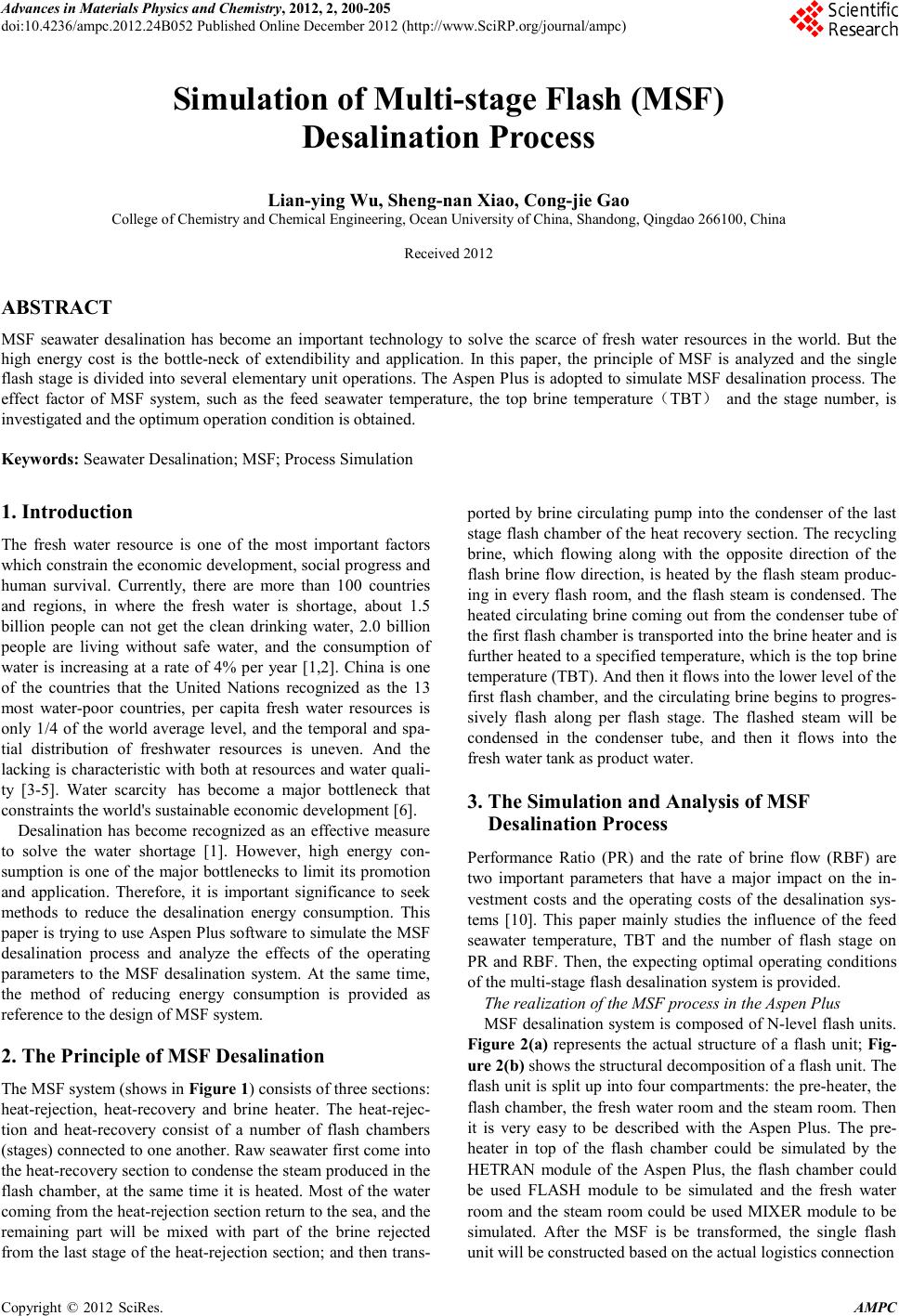 Advances in Ma terials Ph ysics an d Ch e mistry, 2012, 2, 200-205 doi:10.4 236 / ampc .2012.24B052 Published Online December 20 12 (http ://www.SciRP. org/ j ou r nal/ ampc) Copyrigh t © 2012 SciRes. AMPC Simulation of Multi-stage Flash (MSF) Desalination Process Lian-ying Wu, Sheng -na n X iao, Cong-jie Gao College of Chemi st ry and Chemical Engi neering, Oc ean University of China, Shandong, Qingdao 266 100, Chin a Received 20 12 ABSTRACT MSF seawater desalination has become an important technology to solve the scarce of fresh water resources in the world. But the high energy cost is the bottle-neck of extendibility and application. In this paper, the principle of MSF is analyzed and the single flash stage is divided into several elementary unit operations. The Aspen Plus is adopted to simulate MSF desalination process. The effect factor of MSF system, such as the feed seawater temperature, the top brine temperature(TBT) and the stage number, is investigated and the optimum operation condition is obtained. Keywords: S eawater Desalination; MSF; Process Simulation 1. Introduction The fresh water resource is one of the most important factors which constrain the economic development, social progress and human survival. Currently, there are more than 100 countries and regions, in where the fresh water is shortage, about 1.5 billion people can not get the clean drinking water, 2.0 billion people are living without safe water, and the consumption of water is increasing at a rate of 4% per year [ 1,2]. China is one of the countries that the United Nations recognized as the 13 most water-poor countries, per capita fresh water resources is only 1/4 of the world average level, and the temporal and spa- tial distribution of freshwater resources is uneven. And the lacking is ch aracteristic with bo th at reso urces and water quali- ty [3-5]. Water scarcity has become a major bottleneck that constraints the world's sustainable economic development [6]. Desalination has become recognized as an effective measure to solve the water shortage [1]. However, high energy con- sumption is one of the major bottlenecks to limit its promotion and application. Therefore, it is important significance to seek methods to reduce the desalination energy consumption. This paper is trying to use Aspen Plus software to simulate the MSF desalination process and analyze the effects of the operating parameters to the MSF desalination system. At the same time, the method of reducing energy consumption is provided as reference t o the design of MSF s yste m. 2. The Princip le of MSF D esal inat ion The MSF s ystem (shows in Figure 1) consists of three sections: heat-rejection, heat-recovery and brine heater. The heat-rejec- tion and heat-recovery consist of a number of flash chambers (stages) con n ected to one ano ther. Raw seawater fir st co me in to the h eat-reco very sectio n to condense t he st eam produced in the flash chamber, at the same time it is heated. Most of the water coming fro m the heat -reject io n sectio n retu rn to th e sea , and t he remaining part will be mixed with part of the brine rejected from the l ast stage o f the heat-rej ection section; and then tran s- ported by brine circulating pump into the condenser of the last stage flash chamber o f the heat reco very section . The recycling brine, which flowing along with the opposite direction of the flash brine flow direction, is heated by the flash steam produc- ing in every flash room, and the flash steam is condensed. The heated circulating brine coming out from the condenser tube of the first flash chamber is transported into the brine heater and is further heated to a specified temperature, which is the top brine temperature (TBT). And then it flows into the lower level of the first flash chamber, and th e circulating brine begin s to progres- sively flash along per flash stage. The flashed steam will be condensed in the condenser tube, and then it flows into the fresh water tank as product water. 3. The Simulation and Analysis of MSF Desalin ation Proce ss Performance Ratio (PR) and the rate of brine flow (RBF) are two important parameters that have a major impact on the in- vestment costs and the operating costs of the desalination sys- tems [10]. This paper mainly studies the influence of the feed seawater temperature, TBT and the number of flash stage on PR and RBF. Then, the expecting optimal operating conditions of the multi-stage flash desalination system is provided. The realization of the MSF process in the Aspen Plus MSF desalination system is composed of N-level flash units. Figure 2(a) represents the actual structure of a flash unit; Fig- ure 2(b) shows the structural decomposition of a flash unit. The flash unit is split up into four compartments: the pre-heater, the flash chamber, the fresh water room and the steam room. Then it is very easy to be described with the Aspen Plus. The pre- heater in top of the flash chamber could be simulated by the HETRAN module of the Aspen Plus, the flash chamber could be used FLASH module to be simulated and the fresh water room and the steam room could be used MIXER module to be simulated. After the MSF is be transformed, the single flash unit will be constructed based on the actual logistics connection 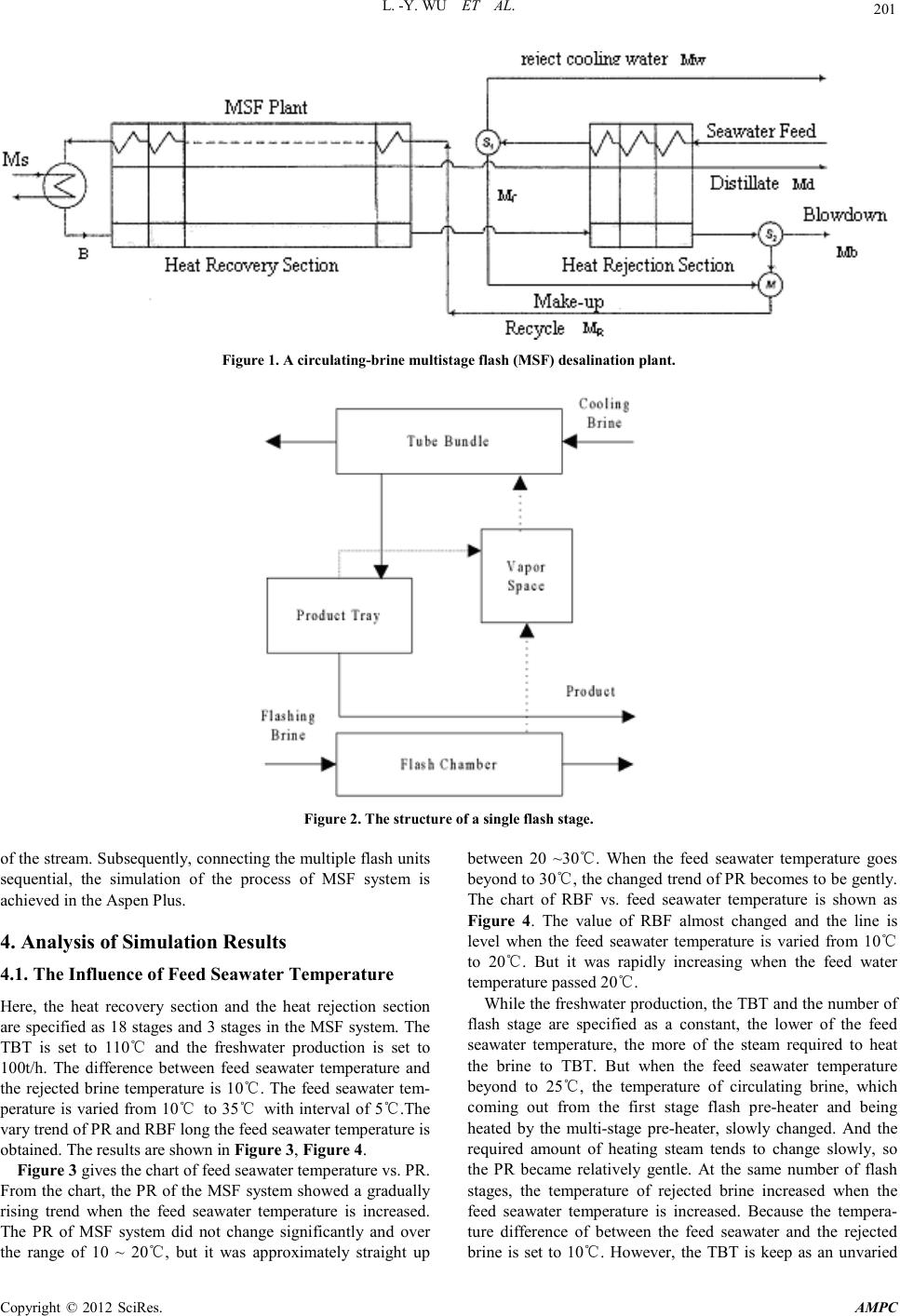 L. -Y. WU ET AL. Copyrigh t © 2012 SciRes. AMPC 201 Figure 1. A circulating-brine multistage flash (MSF ) desalination plant. Figure 2. The structure o f a single flash stage . of the stream. Subsequently, connecting the multiple flash units sequential, the simulation of the process of MSF system is achieved in the Aspen Plus. 4. Analysis of Simulation Results 4.1. The Influence of Feed Seawater Temperature Here, the heat recovery section and the heat rejection section are specified as 18 stages and 3 stages in th e MSF system. The TBT is set to 110℃ and the freshwater production is set to 100t/h. The difference between feed seawater temperature and the rejected brine temperature is 10℃. The feed seawater tem- perature is varied from 10℃ to 3 5℃ with interval of 5℃.The vary trend of PR and RBF long the feed sea water te mperat ure is obtained. The results are shown in Figure 3, Figure 4. Figure 3 gives the chart of feed seawater temperature vs. PR. From the chart, the PR of the MSF system showed a gradually rising trend when the feed seawater temperature is increased. The PR of MSF system did not change significantly and over the range of 10 ~ 20℃, but it was approximately straight up between 20 ~30℃. When the feed seawater temperature goes beyond to 30℃, the changed trend of PR becomes to be gently. The chart of RBF vs. feed seawater temperature is shown as Figure 4. The value of RBF almost changed and the line is level when the feed seawater temperature is varied from 10℃ to 20℃. But it was rapidly increasing when the feed water temperature passed 20℃. While the freshwater production, the TBT and the number of flash stage are specified as a constant, the lower of the feed seawater temperature, the more of the steam required to heat the brine to TBT. But when the feed seawater temperature beyond to 25℃, the temperature of circulating brine, which coming out from the first stage flash pre-heater and being heated by the multi-stage pre-heater, slowly changed. And the required amount of heating steam tends to change slowly, so the PR became relatively gentle. At the same number of flash stages, the temperature of rejected brine increased when the feed seawater temperature is increased. Because the tempera- ture difference of between the feed seawater and the rejected brine is set to 10℃. However, the TBT is keep as an unvaried 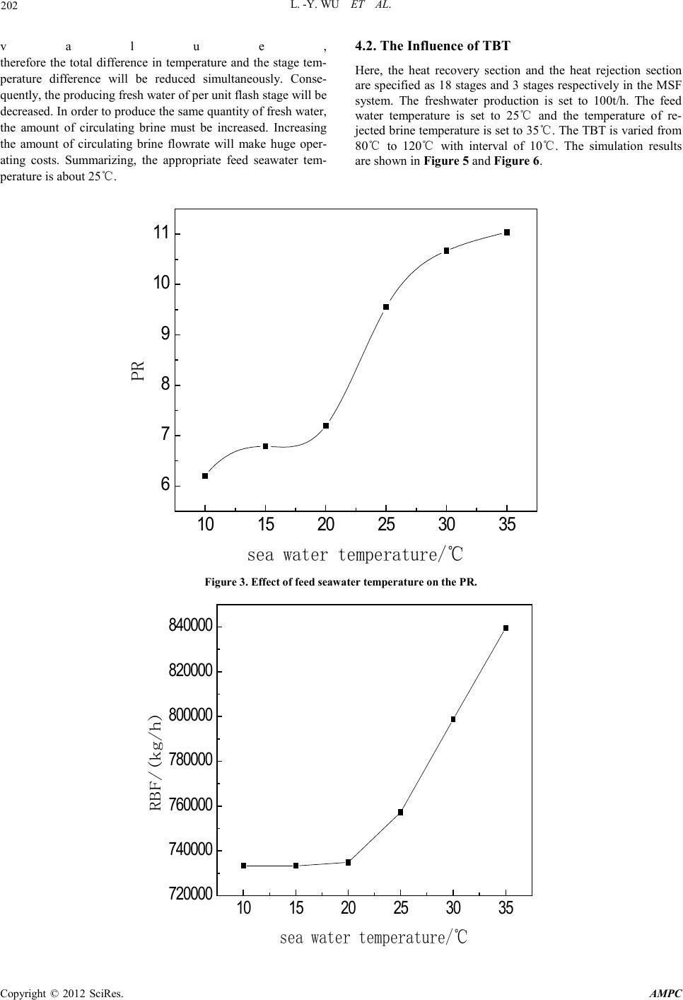 L. -Y. WU ET AL. Copyrigh t © 2012 SciRes. AMPC 202 value, therefore the total difference in temperature and the stage tem- perature difference will be reduced simultaneously. Conse- quently, the producing fresh water of per unit flash stage will be decreased . In or der to produ ce the sa me quan ti ty of fresh water, the amount of circulating brine must be increased. Increasing the amount of circulating brine flowrate will make huge oper- ating costs. Summarizing, the appropriate feed seawater tem- perature is about 25℃. 4.2. The Influence of TBT Here, the heat recovery section and the heat rejection section are specifi ed as 18 stages and 3 stages respecti vely in the MS F system. The freshwater production is set to 100t/h. The feed water temperature is set to 25℃ and the temperature of re- jected b rine t emperature i s set to 3 5℃. The TBT is varied fro m 80℃ to 120℃ with interval of 10℃. The simulation results are shown in Figure 5 and Figure 6. 10 15 20 25 30 35 6 7 8 9 10 11 PR sea water temperature/℃ Figure 3. Effect of feed seawater tempera ture on the PR. 10 15 20 25 30 35 720000 740000 760000 780000 800000 820000 840000 RBF/(kg/h) sea water temperature/℃ 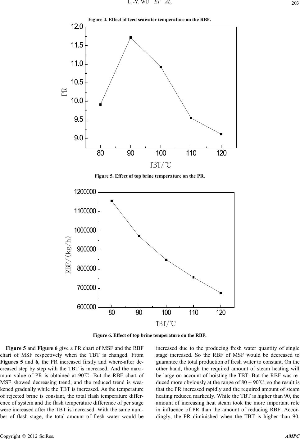 L. -Y. WU ET AL. Copyrigh t © 2012 SciRes. AMPC 203 Figure 4. Effect of feed seawater tempera ture on the RBF. 8090100 110 120 9.0 9.5 10.0 10.5 11.0 11.5 12.0 PR TBT/℃ Figure 5. Effect of top brine temperature on the PR. 8090100 110 120 600000 700000 800000 900000 1000000 1100000 1200000 RBF/(kg/h) TBT/℃ Figure 6. Effect of top brine temperature on the RBF. Figure 5 and Figure 6 give a PR chart o f MSF and the RBF chart of MSF respectively when the TBT is changed. From Figures 5 and 6, the PR increased firstly and where-after de- creased step by step with the TBT is increased. And the maxi- mum value of PR is obtained at 90℃. But the RBF chart of MSF showed decreasing trend, and the reduced trend is wea- kened gradu all y while t he TBT is in creased . As th e temperat ur e of rejected brine is constant, the total flash temperature differ- ence of s ystem and th e flash temp eratu re d ifference o f per s tage were incr eased after th e TBT is incr eased. With t he same num- ber of flash stage, the total amount of fresh water would be increased due to the producing fresh water quantity of single stage increased. So the RBF of MSF would be decreased to guarantee the total production of fresh water to constant. On the other hand, though the required amount of steam heating will be large on account of hoisting the TBT. But the RBF was re- duced more obviously at the range of 80 ~ 90℃, so the result is that the PR increased rapidly and the required amount of steam heating reduced markedly. While the TBT is higher than 90, the amount of increasing heat steam took the more important role in influence of PR than the amount of reducing RBF. Accor- dingly, the PR diminished when the TBT is higher than 90.  L. -Y. WU ET AL. Copyrigh t © 2012 SciRes. AMPC 204 Therefore, considering the performance ratio and operating costs, the TBT of MSF system should be between 90 ~ 110℃ approp ri ate. 4.3. The Influence of F l ash Sta ge Number In this section, the PR and the RBF influenced by the flash stage number will be discussed. The given as fellow: the TBT is 110℃, feed water temperature is 25℃, the temperature of discharged brine is 35℃ and the fresh water production is 100t/h in the MSF system. The results are dep icted in F igure 7 and Figur e 8. When the flash stage number is increased, the PR increased gradual ly, and the more t he stage number is, t he greater the P R is achieved. By contraries, the amount of the circulating brine showed a decreasing t r end. As the sa me total d if ferenc e in temp eratur e is fixed, t he differ - ence in temperature of single stage was decreasing when the number of flash stage was increased. Therefore the flashing of brine would be more close to the reversible process, and the energy loss would be reduced. At the same time, the brine pre-heater could recovery more heat and the required quantity of heating steam could be cut down. Consequently, the PR should be increased. On the other hand, the closer the brine evaporation process to the reversible process, the more the fresh water produced in an single-stage evaporation unit. To holding the same fresh water production, the number of flash stage is bigger and the required amount of the circulating brine is little. But the more stage number, the equipment will become more complexity and the investment costs will be higher. Consider- ing the investment costs and operating costs, the number of flash stage should be more reasonable for the 20-25 level. 18 20 22 24 2628 30 8 9 10 11 12 13 14 15 16 PR stage number Figure 7. Effect of flash stage number on the PR.  L. -Y. WU ET AL. Copyrigh t © 2012 SciRes. AMPC 205 18 20 22 24 2628 30 745000 750000 755000 760000 765000 770000 RBF/(kg/h) stage number Figure 8. Effect of flash stage number on RBF. 5. Conclusions In this paper, multi-stage flash desalination technology is ana- lyzed. The single flash unit is divided into several basic opera- tions, and the Aspen Plus software is used to simulate the mul- ti-stage flash desalination process. Several influenced factor of the MSF system are discussed, such as the feed sea water tem- perature, the TBT and the number of flash stage. The results shown: when the fresh water production, the TBT and the number of flash stage are fixed, the lower the feed water tem- perature, the greater the amount of required external heating steam, the smaller the PR and the greater the amount of circu- lating brine. Similarly, fasting the fresh water production, the feed sea water te mperature an d the number of flash stage, when the top brine temperature was increased, the PR increased at first and then decreased, but the RBF was gradually reduced; With the fresh water production, the TBT and the feed sea wa- ter temperature co nstantly, the P R was increased graduall y and the RBF was reduced gradually when the flash stage number was increasing. Synthetically, the best operating conditions of the MS F system sho uld be selected as follows: feed water te m- perature is 25℃, the TBT is 90 ~ 110℃, and the number of flash stage is 20~ 25. 6. Acknowledgements This work was financially supported by National Natural Science Foundation of China (20976173&21076202). REFERENCES [1] Wang Junhong, Gao Naiyun. Development and application of seawater desalination[J]. Industrial Water Treatment, 2009, 28(5) [2] Bai Yuhui, Yan Zhengyuan. Summary of desalination technolo- gy. Shandong Water Conservancy College. 1995. [3] Cai Xiaojun, Zhou Shaoxiang. Low-temperature multi-effect desalination plant system analysis. North China Electric Power University, 2009. [4] Ji e Lixi n, Ruan Guoling. Status and Prospect of reverse osmosis desalination technology. China Water & Wastewater. 2000, 16(3):24-27. [5] Lin Siqing. Seawater reverse osmosis desalination technology abroad, and Future. Water Treatment. 1998, 24(1): 1-6 [6] Zhou Shaoxiang, Song Zhiping. Multi-stage flash desalination cogenerat ion tec hnology, t heory and p ractice. North China Elec- tric Power University.2001. [7] Osman A. Hamed, Holayil A. Al-Otaibi. Prospects of operation of MSF desalination plants at high TBT and low antiscalant dos- ing rate. ScienceDirect, Desalination 256 (2010) 181~189 [8] Hittman Assciates,Inc.,OSW Res.Devel.Prog.Rep.,No.490 ,1969 [9] Wang Shichang, Seawater desalination project. Beijing: Chemi- cal Industry Press. 2003: 8-29 [10] Gao Congjie, Cheng Guohua. Desalination Technology and Engineering Handbook. Beijing: Chemical Industry Press, 2004: 5-90 [11] Khawla AbdulMohsen Al-Shayji.Modeling,simulation,and opti- mization of large-scale commercial desalination plants, the Vir- ginia Polytechnic Institute and State University, April, 17, 1998. |