Paper Menu >>
Journal Menu >>
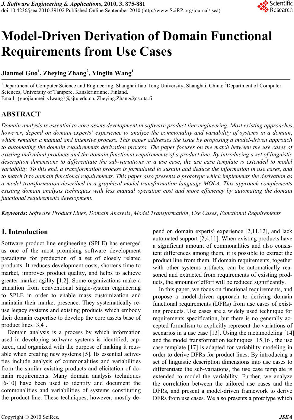 J. Software Engineering & Applications, 2010, 3, 875-881 doi:10.4236/jsea.2010.39102 Published Online September 2010 (http://www.SciRP.org/journal/jsea) Copyright © 2010 SciRes. JSEA 875 Model-Driven Derivation of Domain Functional Requirements from Use Cases Jianmei Guo1, Zheying Zhang2, Yinglin Wang1 1Department of Computer Science and Engineering, Shanghai Jiao Tong University, Shanghai, China; 2Department of Computer Sciences, University of Tampere, Kanslerinrinne, Finland. Email: {guojianmei, ylwang}@sjtu.edu.cn, Zheying.Zhang@cs.uta.fi ABSTRACT Domain analysis is essential to core assets development in software product line engineering. Most existing approaches, however, depend on domain experts’ experience to analyze the commonality and variability of systems in a domain, which remains a manual and intensive process. This paper addresses the issue b y proposing a m odel-driven approach to automating the domain requirements derivation process. The paper focuses on the match between the use cases of existing individual products and the domain functional requirements of a product line. By introducing a set of linguistic description dimensions to differentiate the sub-variations in a use case, the use case template is extended to model variability. To this end, a tran sformation process is formulated to su stain and deduce the info rmation in use cases, and to match it to do main fun ctional requiremen ts. This paper also presents a prototype which implements the derivation as a model transformation described in a graphical model transformation language MOLA. This approach complements existing domain analysis techniques with less manual operation cost and more efficiency by automating the domain functional requirements development. Keywords: Software Product Lines, Domain Analysis, Model Transformation, Use Cases, Functional Requirements 1. Introduction Software product line engineering (SPLE) has emerged as one of the most promising software development paradigms for production of a set of closely related products. It reduces development costs, shortens time to market, improves product quality, and helps to achieve greater market agility [1,2]. Some organizations make a transition from conventional single-system engineering to SPLE in order to enable mass customization and maintain their market presence. They systematically re- use legacy systems and existing products which embody their domain expertise to develop the core assets base of product lines [3,4]. Domain analysis is a process by which information used in developing software systems is identified, cap- tured, and organized with the purpose of making it reus- able when creating new systems [5]. Its essential active- ties include analysis of commonalities and variabilities from the similar existing products and elicitation of do- main requirements. Many domain analysis techniques [6-10] have been used to identify and document the commonalities and variabilities of systems constituting the product line. These techniques, however, mostly de- pend on domain experts’ experience [2,11,12], and lack automated support [2,4,11]. Wh en existing p roducts have a significant amount of commonalities and also consis- tent differences among them, it is possible to extract the product line from them. If domain requ irements, together with other systems artifacts, can be automatically rea- soned and extracted from requirements of existing prod- ucts, the amount of effort will be reduced significantly. In this paper, we focus on functional requirements, and propose a model-driven approach to deriving domain functional requirements (DFRs) from use cases of exist- ing products. Use cases are a widely used technique for requirements specification, but there is no generally ac- cepted formalism to explicitly represent the variations of scenarios in a use case [13]. Using the metamodeling [14] and the model transformation techniques [15,16], the use case template [17] is adapted for variability modeling in order to derive DFRs for product lines. By introducing a set of linguistic description dimensions into use cases to differentiate the sub-variations, the use case template is extended to model the variability. Further, we analyze the correlation between the tailored use cases and the DFRs, and present a model-driven framework to derive DFRs from use cases. We also presents a prototype w hic h 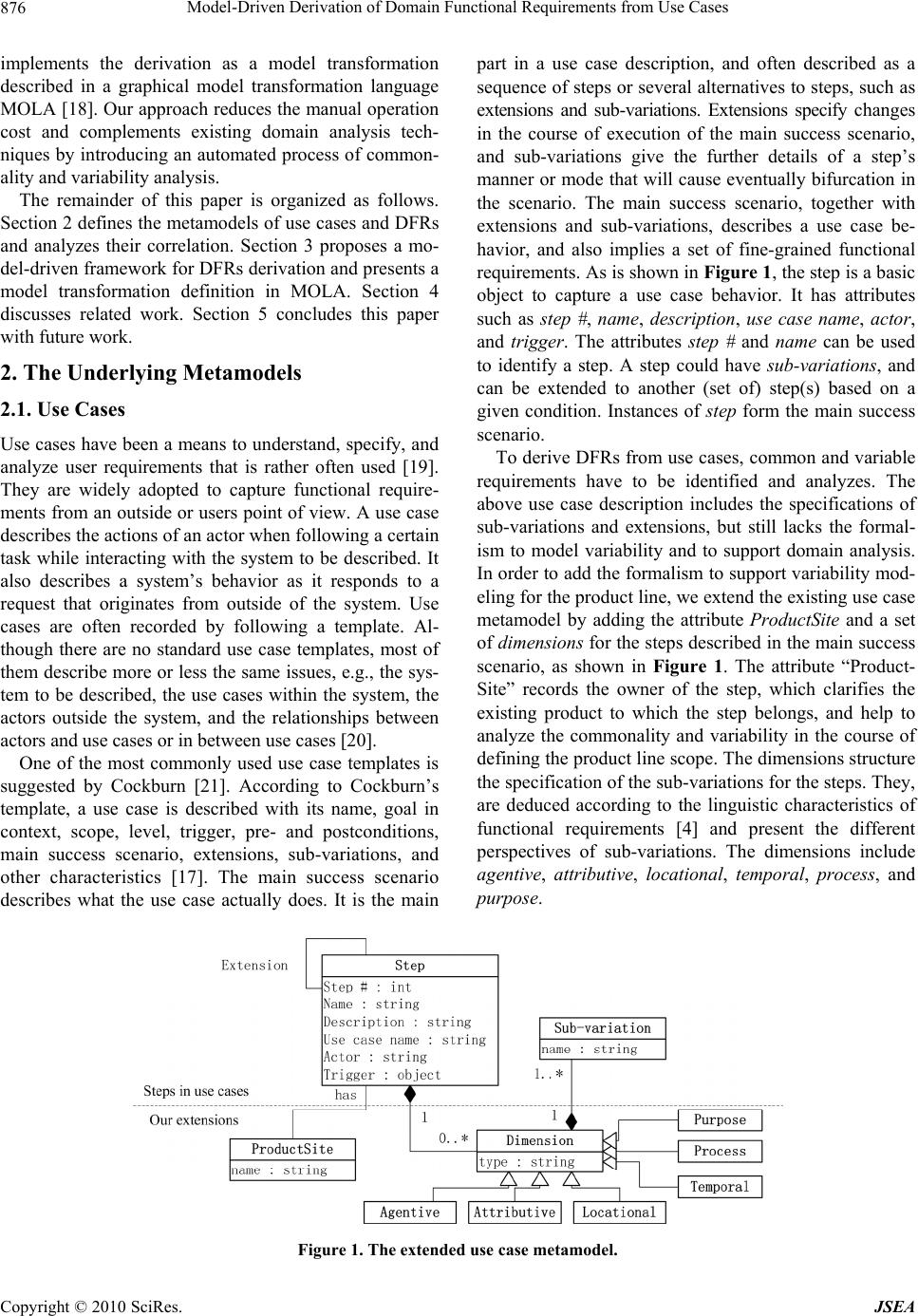 Model-Driven Derivation of Domain Functional Requirements from Use Cases Copyright © 2010 SciRes. JSEA 876 implements the derivation as a model transformation described in a graphical model transformation language MOLA [18]. Our approach reduces the manual operation cost and complements existing domain analysis tech- niques by introducing an automated process of common- ality and variability analysis. The remainder of this paper is organized as follows. Section 2 defines the metamodels of use cases and DFRs and analyzes their correlation. Section 3 proposes a mo- del-driven framework for DFRs derivation and presents a model transformation definition in MOLA. Section 4 discusses related work. Section 5 concludes this paper with future work. 2. The Underlying Metamodels 2.1. Use Cases Use cases have been a means to understand, specify, and analyze user requirements that is rather often used [19]. They are widely adopted to capture functional require- ments from an outside or users point of view. A use case describes the actions of an actor when following a certain task while interacting with the system to be described. It also describes a system’s behavior as it responds to a request that originates from outside of the system. Use cases are often recorded by following a template. Al- though there are no standard use case templates, most of them describe more or less the same issues, e.g., the sys- tem to be described, the use cases within the system, the actors outside the system, and the relationships between actors and use cases or in between use cases [20]. One of the most commonly used use case templates is suggested by Cockburn [21]. According to Cockburn’s template, a use case is described with its name, goal in context, scope, level, trigger, pre- and postconditions, main success scenario, extensions, sub-variations, and other characteristics [17]. The main success scenario describes what the use case actually does. It is the main part in a use case description, and often described as a sequence of steps or several alternatives to steps, such as extensions and sub-variations. Extensions specify changes in the course of execution of the main success scenario, and sub-variations give the further details of a step’s manner or mode that will cause eventually bifurcation in the scenario. The main success scenario, together with extensions and sub-variations, describes a use case be- havior, and also implies a set of fine-grained functional requirements. As is shown in Figure 1, the step is a basic object to capture a use case behavior. It has attributes such as step #, name, description, use case name, actor, and trigger. The attributes step # and name can be used to identify a step. A step could have sub-variations, and can be extended to another (set of) step(s) based on a given condition. Instances of step form the main success scenario. To derive DFRs from use cases, common and variable requirements have to be identified and analyzes. The above use case description includes the specifications of sub-variations and extensions, but still lacks the formal- ism to model variability and to support domain analysis. In order to add the formalism to support variability mod- eling for th e pro duct lin e, we extend th e existin g u se case metamodel by adding the attribute ProductSite and a set of dimensions for the steps described in the main success scenario, as shown in Figure 1. The attribute “Product- Site” records the owner of the step, which clarifies the existing product to which the step belongs, and help to analyze the commonality and variability in the course of defining the product line scope. The dimensions structure the specification of the sub-variations for the steps. They, are deduced according to the linguistic characteristics of functional requirements [4] and present the different perspectives of sub-variations. The dimensions include agentive, attributive, locational, temporal, process, and purpose. Figure 1. The extended use case metamodel.  Model-Driven Derivation of Domain Functional Requirements from Use Cases Copyright © 2010 SciRes. JSEA 877 Agentive defines the agent(s) whose activities will bring about the state of affairs implied by the step, e.g., “{author}Agentive submits an article”. Attributive defines the attributes of the agentive or of the object associated with the action implied by the step, e.g., “submit a {re- search, review}Attributive article”. Locational defines the spatial location(s) where the activity implied by the step is supposed to take place, e.g., “submit an article {at of- fice, at home}Locational”. Temporal defines the duration or frequency of the activity implied by the step, e.g., “sub- mit an article {every week, every month}Temporal”. Proc- ess defines the instrument, the means and the manner by which the activity is performed, e.g., “submit an article by {email, submission system}Process”. Purpose defines the purpose that the agentive carries out the activity or that the objective is affected by the activity implied by the step, e.g., “submit an article for {propagating the knowledge}Purpose”. The extended us e case metamodel mainly invo lves the steps, the sub-variations and the extensions because these elements from Cockburn’s template have the direct rela- tionship with functional requirements. It also models the variability through in troducing a set of linguistic descrip - tion dimensions to differentiate the sub-variations. The product site of each step is added for further analyzing the commonality and variability of DFRs. 2.2. Domain Functional Requirements DFRs specify the common and variable requirements for all foreseeable applications of the product line. Accord- ing to the Orthogonal Variability Model (OVM) [2], we define the variability model of DFRs in Figure 2. Besides the essential attribu tes of a DFR, i.e. name and description, a DFR shall document its variability. Vari- ability comprises the variability subject and the variabil- ity object. A variability subject is a variable item or a variable property of such an item [2]. If a DFR or its property has the tendency to change, it is a variability subject. The property with tendency to change can be further defined as a variation point. A DFR could have one or more variation points. In general, a variation point of a DFR expresses a variable semantic concern of the DFR. To present different semantic concerns of a DFR, we also define a set of types for the variation points of DFRs according to the linguistic characteristics of func- tional requirements [4], i.e . agen tive, attributive, loca - tional, temporal, process, and purpose. A variability object is a particular instance of a vari- ability subject [2]. It is represented as a variant. A variant represents a single option of the semantic concern that the variation point expresses, and a variation point may have one or more variants. A DFR could come from one or more product sites in a product line. Such product sites can be used to calculate the CV ratio (Commonality/Variability rati o). A CV ratio records the frequency a DFR appears in a domain. Engi- neers can use the CV ratios to decide whether a DFR is common or optional. Generally, a DFR is common if it has a CV ratio “100%”. A DFR constraint documents a relationship between two DFRs, betw een a vari ant and a DFR, or betw een two variants. There are two types of relationship, i.e. requires and excludes. Each DFR constraint has a domain and a range. A domain of a constraint is the constraint’s sub- ject that possesses the constraint relation; a range of a constraint is the constraint’s object that is affected by the constraint relation. For example, a constraint “A requires B” expresses the constraint relation “requires” between its domain “A” and its range “B”. A domain or a range also has its “name” and its “type”. 2.3. Correlation between Use Cases and Domain Functional Requirements Steps presented in our prior metamodel describe the Figure 2. The domain functional requirement metamodel. 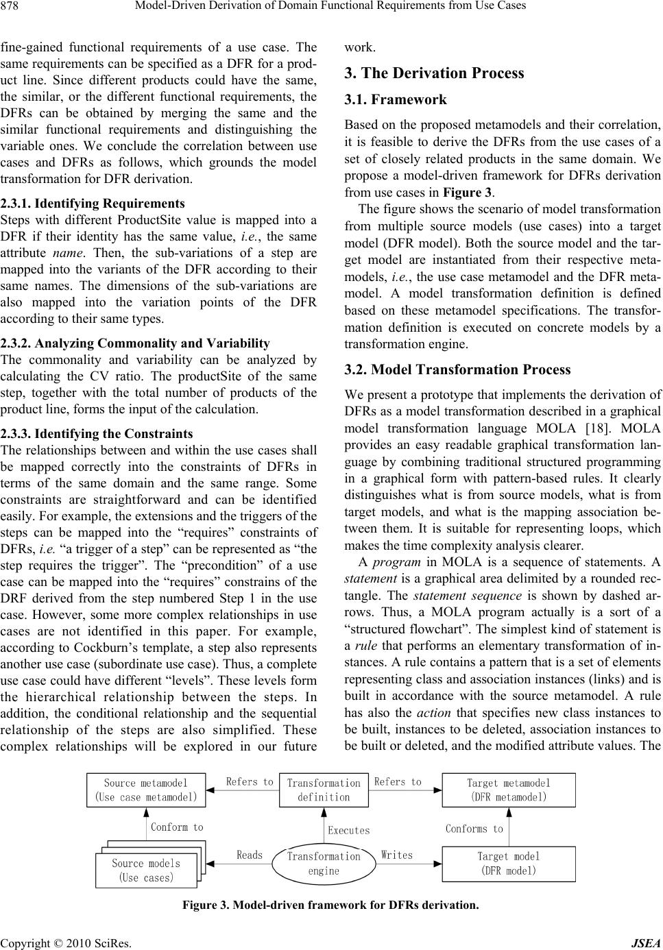 Model-Driven Derivation of Domain Functional Requirements from Use Cases Copyright © 2010 SciRes. JSEA 878 fine-gained functional requirements of a use case. The same requirements can be specified as a DFR for a prod- uct line. Since different products could have the same, the similar, or the different functional requirements, the DFRs can be obtained by merging the same and the similar functional requirements and distinguishing the variable ones. We conclude the correlation between use cases and DFRs as follows, which grounds the model transformation fo r DFR derivati on . 2.3.1. Identifying Requirements Steps with different ProductSite value is mapped into a DFR if their identity has the same value, i.e ., the same attribute nam e. Then, the sub-variations of a step are mapped into the variants of the DFR according to their same names. The dimensions of the sub-variations are also mapped into the variation points of the DFR according to their same types. 2.3.2. Analyzing Commonality and Variability The commonality and variability can be analyzed by calculating the CV ratio. The productSite of the same step, together with the total number of products of the product line, forms the input of the calculation. 2.3.3. Id e ntifyi n g th e Constraints The relationships between and within the use cases shall be mapped correctly into the constraints of DFRs in terms of the same domain and the same range. Some constraints are straightforward and can be identified easily. For example, the extensions and the triggers of the steps can be mapped into the “requires” constraints of DFRs, i.e. “a trigger of a step” can be represented as “the step requires the trigger”. The “precondition” of a use case can be mapped into the “requires” constrains of the DRF derived from the step numbered Step 1 in the use case. However, some more complex relationships in use cases are not identified in this paper. For example, according to Cockburn’s template, a step also represents another use case (subordinate use case). Thus, a complete use case could have different “levels”. These levels form the hierarchical relationship between the steps. In addition, the conditional relationship and the sequential relationship of the steps are also simplified. These complex relationships will be explored in our future work. 3. The Derivation Process 3.1. Framework Based on the proposed metamodels and their correlation, it is feasible to derive the DFRs from the use cases of a set of closely related products in the same domain. We propose a model-driven framework for DFRs derivation from use cases in Figure 3. The figure shows the scenario of model transformation from multiple source models (use cases) into a target model (DFR model). Both the source model and the tar- get model are instantiated from their respective meta- models, i.e., the use case metamodel and the DFR meta- model. A model transformation definition is defined based on these metamodel specifications. The transfor- mation definition is executed on concrete models by a transformation eng ine. 3.2. Model Transformation Process We present a prototyp e that implements the derivation of DFRs as a model transformation described in a graphical model transformation language MOLA [18]. MOLA provides an easy readable graphical transformation lan- guage by combining traditional structured programming in a graphical form with pattern-based rules. It clearly distinguishes what is from source models, what is from target models, and what is the mapping association be- tween them. It is suitable for representing loops, which makes the time complexity analysis clearer. A program in MOLA is a sequence of statements. A statement is a graphical area delimited by a rounded rec- tangle. The statement sequence is shown by dashed ar- rows. Thus, a MOLA program actually is a sort of a “structured flowchart”. The simplest kind of statement is a rule that performs an elementary transformation of in- stances. A rule contains a pattern that is a set of elements representing class and association instances (links) and is built in accordance with the source metamodel. A rule has also the action that specifies new class instances to be built, instances to be deleted, association instances to be built or deleted, and the modified attribu te values. The Figure 3. Model-driven framework for DFRs derivation. 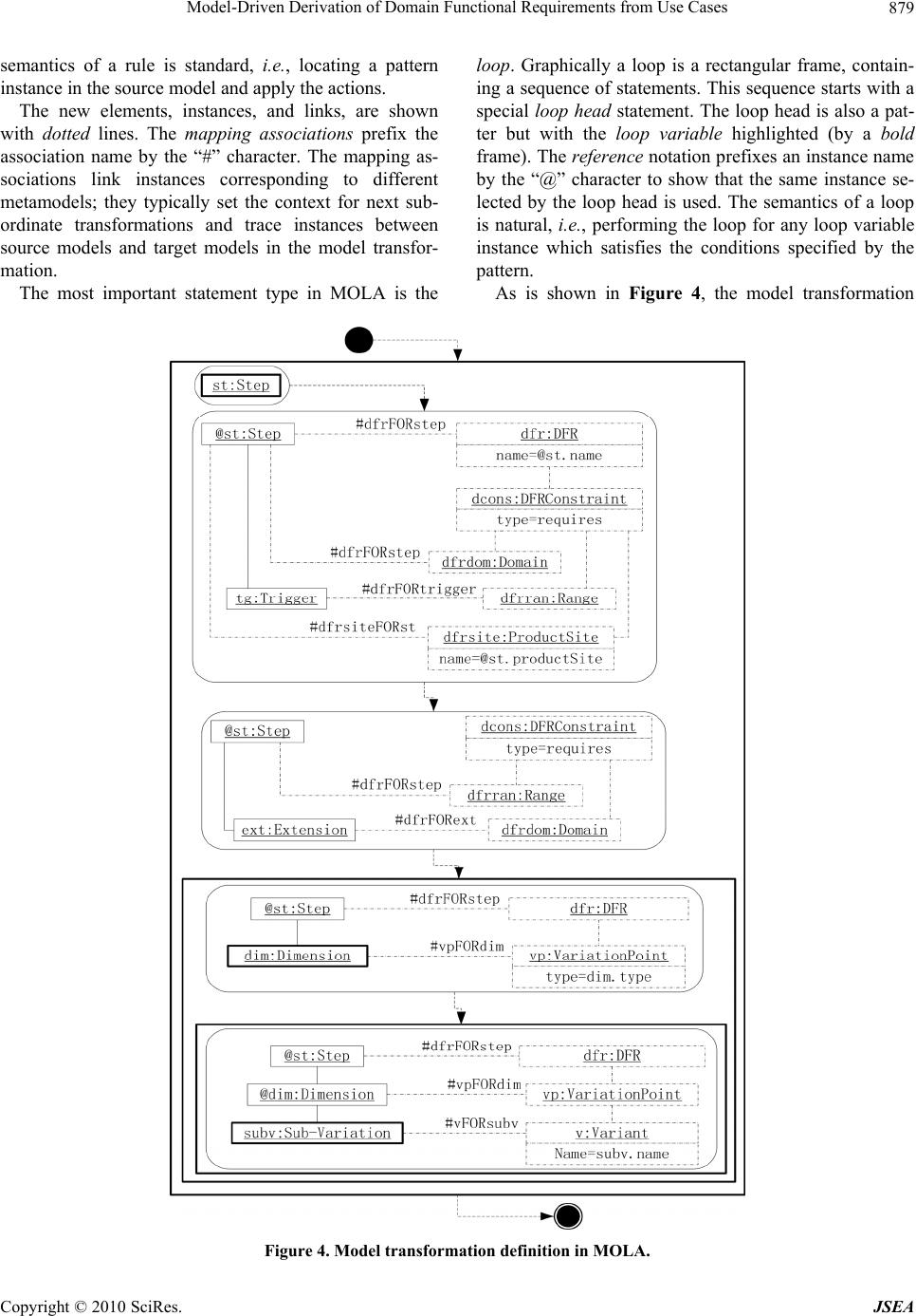 Model-Driven Derivation of Domain Functional Requirements from Use Cases Copyright © 2010 SciRes. JSEA 879 semantics of a rule is standard, i.e., locating a pattern instance in the source model and apply the actions. The new elements, instances, and links, are shown with dotted lines. The mapping associations prefix the association name by the “#” character. The mapping as- sociations link instances corresponding to different metamodels; they typically set the context for next sub- ordinate transformations and trace instances between source models and target models in the model transfor- mation. The most important statement type in MOLA is the loop. Graphically a loop is a rectangular frame, contain- ing a sequence of statements. This sequence starts with a special loop head statement. The loop head is also a pat- ter but with the loop variable highlighted (by a bold frame). The reference notation prefixes an instan ce name by the “@” character to show that the same instance se- lected by the loop head is used. The semantics of a loop is natural, i.e., performing the loop for any loop variable instance which satisfies the conditions specified by the pattern. As is shown in Figure 4, the model transformation Figure 4. Model transformation definition in MOLA.  Model-Driven Derivation of Domain Functional Requirements from Use Cases Copyright © 2010 SciRes. JSEA 880 from use cases to DFRs contains three nested loops. The outer loop is executed for each step instance. The next statement is a rule building a DFR from a set of steps according to their same names. The mapping association “#dfrFORst” records which DFR from which step actu- ally has been generated and can be reused in the follow- ing statements. Thus, all input steps with the same name will be merged as one DFR. Meanwhile, the rule also identifies these steps’ product sites to build the DFR’s product sites. Next, the extensions and the trigger of the step are transformed into the “requires” DFR constraints. The middle-level loop is executed for each dimension of the steps. Its rule builds the variation points from the dimensions according to their same types. Its pattern ref- erences the “#dfrFORst” mapping association built by the previous statement. The loop head “dim:Dimension” is combined with building actions. Thus, all the dimen- sions, having the same type and belonging to a set of steps with the same names, will be merged as one varia- tion point of the DFR that is generated by the set of steps. The inner loop is executed for each sub-variation of some dimension of some step. Its rule builds a variant through merging a set of sub-variations with the same name. Note that the CV ratios of DFRs will be calculated according to the product sites of DFRs after the model transformation process. For those steps without sub- variations, only the outer loop will be executed for ana- lyzing their commona lity and variability. 4. Related Work and Discu ss io n Some researchers have studied how to extend use cases with variability. They exploit and extend the use cases for product lines in different perspectives and by differ- ent means. For example, Jacobson et al. [8] introduce variation points into use case diagrams and use them to describe different ways of performing actions within a use case. Gomaa [22] and John and Muthig [13] intro- duce stereotypes, such as <<variant>>, <<kernel>> and <<optional>> for use cases for modeling families of sys- tems. Most research remains the documentation of vari- abilities, but ignores the princip le of SPLE, i.e. proactive reuse. Topics such as how to systematically reuse exist- ing requirements to derive domain requirements lack enough research. In this paper, we extend use cases with a multi-dimensional structure for modeling the variability, and record the product site of each step in use cases. These extensions support systematic reuse of domain knowledge by deriving domain requirements from exist- ing use cases, and analyzing the commonality and vari- ability. Many domain analysis methods, such as FODA (Fea- ture-Oriented Domain Analysis) [6], FORM (Fea- ture-Oriented Reuse Method) [7], SCV (Scope, Com- monality, and Variability) [10], RSEB [8] and Fea- tuRSEB [9], identify and document the commonalities and variabilities of related systems in a domain. Never- theless, these typical domain analysis techniques mostly depend on domain experts’ knowledge and experience to manually acquire commonalities and variabilities. In ad- dition, Br aganca and Machad o [23] and Wang et al. [24] propose automated approaches to transformation between feature models and use cases. Our approach comple- ments the existing domain analysis techniques by pro- viding automated support for developing DFRs from use cases. Manual effort is yet indispensable in our approach. First, analysts must scope domain requirements and for- mulate domain terminology. Second, each use case must be specified with the predefined use case metamodel and unified domain terminology, which helps uncover the incompleteness and inconsistency of existing require- ments to a certain degree. Although NLP techniques could be incorporated into DFRs development to mini- mize the manual operation cost [4], their accuracy can not yet be guaranteed sufficiently. Third, a comprehend- sive analysis of variability dependencies must be don e by analysts in terms of domain contex t. In summary, domain experts still play an essential role in the DFRs develop- ment. 5. Conclusions In this paper, we propose an automated approach to DFRs derivation using the metamodeling and model transformation techniques. The main contribution is to present a model-driven approach to domain requirements analysis. The approach complements the existing domain analysis techniques by reducing the manual operation cost and improving the efficiency in DFRs development, which further enhances the transition process from sin- gle-system engineering to SPLE. In addition, the model transformation definition documents the traceability in- formation between DFRs and use cases, which helps manage domain requirements and trace their rationale for decision making in SPLE. Our future work is twofold. First, we will further im- prove our current approach, especially exploring how to handle the complex constraint dependency. Second, we will verify our approach throug h an in-depth experiment- tal study. 6. Acknowledgements This work is supported by the National Natural Science Foundation of China (NSFC No. 60773088), the National  Model-Driven Derivation of Domain Functional Requirements from Use Cases Copyright © 2010 SciRes. JSEA 881 High-tech R & D Program of China (863 Program No. 2009AA04Z106), and the Key Program of Basic Res- earch of Shanghai Municipal S & T Commission (No. 08JC1411700). REFERENCES [1] P. Clements and L. Northrop, “Software Product Lines: Pr ac t ic e s an d P at te r n s, ” A dd i so n We s le y , Boston, 2001. [2] K. Pohl, G. Bockle and F. van der Linden, “Software Product Line Engineering: Foundations, Principles and Techniques,” Springer Verlag, Heidelberg, 2005. [3] C. W. Krueger, “Easing the Transition to Software Mass Customization,” Proceedings International Workshop on Product Family Engine e ri n g, Bilbao, 2001, pp. 282-293. [4] N. Niu and S. Easterbrook, “Extracting and Modeling Product Line Functional Requirements,” Proceedings RE’08, Barcelona, 2008, pp. 155-164. [5] R. Prieto-Diaz, “Domain Analysis for Reusability,” Pro- ceedings 11th Annual International Computer Software and Applications Conference, Tokyo, 1987, pp. 23-29. [6] K. C. Kang, S. G. Cohen, J. A. Hess, W. E. Novak and A. S. Peterson, “Feature-Oriented Domain Analysis (FODA) Feasibility Study,” Technical Report CMU/SEI-90-TR- 021, Software Engineering Institute, Canadian Mennonite University, 1990. [7] K. C. Kang, S. Kim, J. Lee, K. Kim, E. Shin and M. Huh, “FORM: A Feature-Oriented Reuse Method with Do- main-Specific Reference Architectures,” Annals of Soft- ware Engineering, Vol. 5, No. 1, 1998, pp. 143-168. [8] I. Jacobson, M. Griss and P. Jonsson, “Software Reuse: Architecture Process and Organization for Business Suc- cess,” Association for Computing Machinery Press, 1997. [9] M. L. Griss, J. Favaro and M. D. Alessandro, “Integrating Feature Modeling with the RSEB,” Proceedings of Inter- national Conference on Steel Rolling’98, Victoria, 1998, pp. 76-85. [10] J. Coplien, D. Hoffman and D. Weiss, “Commonali ty and Variability in Software Engineering,” IEEE Software, Vol. 15, No. 6, 1998, pp. 37-45. [11] M. Moon, H. S. Chae and K. Yeom, “An Approach to Developing Domain Requirements as a Core Asset Based on Commonality and Variability Analysis in a Product Line,” IEEE Transactions on Software Engineering, Vol. 31, No. 7, 2005, pp. 551-569. [12] E. de Almeida, J. Mascena, A. Cavalcanti, A. Alvaro, V. Garcia, S. de Lemos Meira and D. Lucrédio, “The Do- main Analysis Concept Revisited: A Practical Approach,” Proceedings of International Conference on Steel Roll- ing’06, Turin, 2006, pp. 43-57. [13] I. John and D. Muthig, “Tailoring Use Cases for Product Line Modeling,” Proceedings of Requirements Engineer- ing for Product Lines’02, Essen, 2002, pp. 26-32. [14] Z. Zhang, “Model Component Reuse-Conceptual Foun- dations and Application in the Metamodel-Based Systems Analysis and Design Environment,” Ph.D. dissertation, Jyvaskyla Studies in Computing 39, University of Jy- vaskyla, 2004. [15] A. G. Kleppe, J. B. Warmer and W. Bast, “MDA Ex- plained: The Model Driven Architecture: Practice and Promise,” Addison Wesley, Longman Publishing Co., Inc., Boston, 2003. [16] S. Sendall and W. Kozaczynski, “Model Transformation: The Heart and Soul of Model-Driven Software Develop- ment,” IEEE Software, Vol. 20, No. 5, 2003, pp. 42-45. [17] A. Cockburn, “Basic Use Case Template,” 2010. http:// alistair.cockburn.us/Basic+use+case+template. [18] A. Kalnins and J. B. E. Celms, “Model Transformation Language MOLA,” Proceedings of Working Conference on Model Driven Architecture: Foundations and Applica- tions (MDAFA’04), Linköping, 2004, pp. 62-76. [19] I. Jacobson, “Object-Oriented Software Engineering: A Use Case Driven Approach,” Addison Wesley, Woking- ham, England, 1992. [20] Object Management Group, “Unified Modeling Language (UML), version 2.2,” 2010. http://www.omg.org/techno- logy/documents/formal/uml.htm. [21] A. Cockburn, “Writing Effective Use Cases,” Addison Wesley, Boston, 2001. [22] H. Gomaa, “Object Oriented Analysis and Modeling for Families of Systems with UML,” Proceedings of Inter- national Conference on Steel Rolling’00, Vienna, 2000, pp. 89-99. [23] A. Braganca and R. J. Machado, “Automating Mappings between Use Case Diagrams and Feature Models for Software Product Lines,” Proceedings of Southern Pover- ty Law Center’07, Kyoto, 2007, pp. 3-12. [24] B. Wang, W. Zhang, H. Zhao, Z. Jin and H. Mei, “A Use Case Based Approach to Feature Models’ Construction,” Proceedings RE’09, Atlanta, Georgia, 2009, pp. 121-130. |