Paper Menu >>
Journal Menu >>
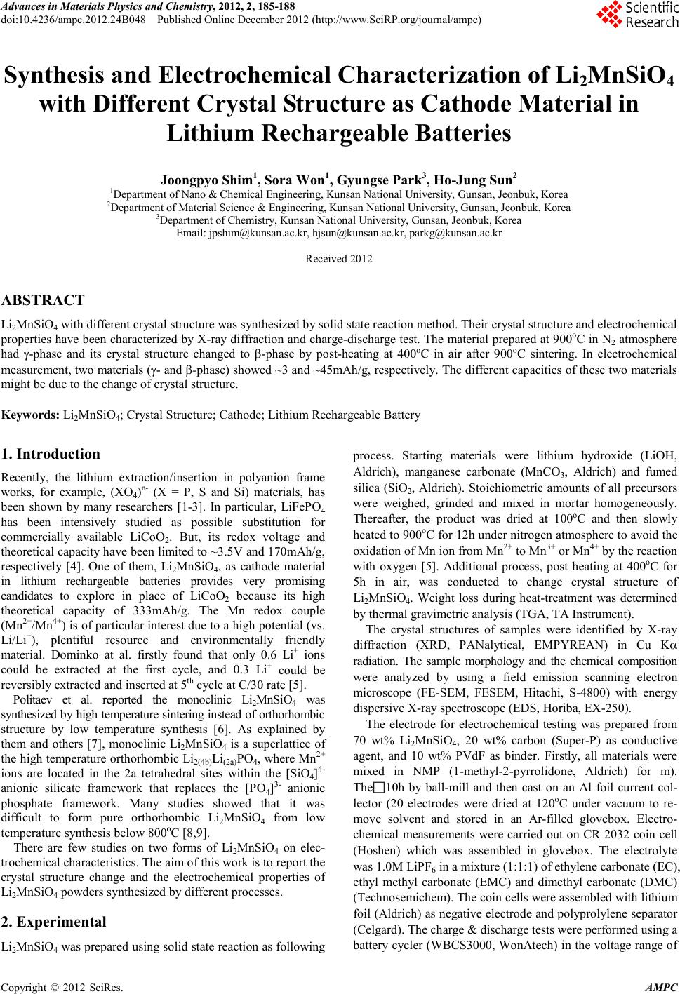 Advances in Ma terials Physics and Che mist ry, 2012, 2, 185-188 doi:10.4236/ampc.2012.24B048 Published Online December 2012 (http ://www.SciRP.org/journal/ampc) Copyright © 2012 SciRes. AMPC Synthesis and Electrochemical Characterization of Li2MnSiO4 with Different Crystal Structure as Cathode Material in Lithium Rechargeable Batteries Joongpyo Shim1, Sora Won1, Gyungse Park3, Ho-Jung Sun2 1Department of Nano & Chemical Engineering, Kunsan National University, Gunsan, Jeonbuk, Korea 2Department of M ater ial S cien ce & Engineer in g , Kuns an National University, Guns an, Jeonb uk, Korea 3Department of Chemistry, Kunsan National University, Gunsan, Jeonbuk, Korea Email: jpshim@kunsan.ac.kr, hjsun@kunsan.ac.k r , p arkg@kun san.ac.kr Received 2012 ABSTRACT Li2MnSiO4 with d ifferent crystal stru cture was synthesi zed by solid state reaction method . Their cryst al structure an d electrochemical propert ies have been characterize d by X-ray dif fraction and charge-discharge tes t. The materi al prepared at 900oC in N2 atmosphere had γ-phase and its crystal structure changed to β-phase by post-heating at 400oC in air after 900oC sintering. In electrochemical measure ment, t wo materials (γ- and β-phase) showed ~3 and ~45mAh/g, resp ectively. The differen t capacit ies of these two material s might b e due to the change of cryst al structure. Keywords: Li2MnSiO4; Crystal Structure; Cathode; Lithium Rechar geable Battery 1. Introduction Recently, the lithium extraction/insertion in polyanion frame works, for example, (XO4)n- (X = P, S and Si) materials, has been shown by many researchers [1-3]. In particular, LiFePO4 has been intensively studied as possible substitution for commercially available LiCoO2. But, its redox voltage and theoretical capacity have been limited to ~3.5V and 170mAh/g, respectively [4]. One of them, Li2MnSiO4, as cathode material in lithium rechargeable batteries provides very promising candidates to explore in place of LiCoO2 because its high theoretical capacity of 333mAh/g. The Mn redox couple (Mn2+/Mn4+) is of particular interest due to a high potential (vs. Li/Li+), plentiful resource and environmentally friendly material. Dominko at al. firstly found that only 0.6 Li+ ions could be extracted at the first cycle, and 0.3 Li+ could be reversibly extracted and inserted at 5th cycle at C/30 r ate [5]. Politaev et al. reported the monoclinic Li2MnSiO4 was synthesized by high temperature sintering instead of orthorhombic structure by low temperature synthesis [6]. As explained by them and others [7], monoclinic Li2MnSiO4 is a superlattice of the high temperature orthorhombic Li2(4b)Li(2a)PO4, where Mn 2+ ions are located in the 2a tetrahedral sites within the [SiO4]4- anionic silicate framework that replaces the [PO4]3- anionic phosphate framework. Many studies showed that it was difficult to form pure orthorhombic Li2MnSiO4 from low temperature synthesis below 800oC [8,9]. There are few studies on two forms of Li2MnSiO4 on elec- trochemical chara cteristi cs. The aim of this work is to report the crystal structure change and the electrochemical properties of Li2MnSiO4 powders synthesized by different processes. 2. Experimental Li2MnSiO4 was prepared using solid state reaction as following process. Starting materials were lithium hydroxide (LiOH, Aldrich), manganese carbonate (MnCO3, Aldrich) and fumed silica (SiO2, Aldrich). Stoichiometric amounts of all precursors were weighed, grinded and mixed in mortar homogeneously. Thereafter, the product was dried at 100oC and then slowly heated to 900oC for 12h under nitrogen atmosphere to avoid the oxidation of Mn ion from Mn2+ to Mn3+ or Mn4+ b y the reacti on with oxygen [5]. Additional process, post heating at 400oC for 5h in air, was conducted to change crystal structure of Li2MnSiO4. Weight loss during heat-treatment was determined by ther mal gravimetric analysi s ( TGA, TA Instrument). The crystal structures of samples were identified by X-ray diffraction (XRD, PANalytical, EMPYREAN) in Cu Kα radiation. The sample morphology and the chemical composition were analyzed by using a field emission scanning electron microscope (FE-SEM, FESEM, Hitachi, S-4800) with energy disp ersive X-ray spect r oscope (EDS, Horiba, EX-250). The electrode for electrochemical testing was prepared from 70 wt% Li2MnSiO4, 20 wt% carbon (Super-P) as conductive agent, and 10 wt% PVdF as binder. Firstly, all materials were mixed in NMP (1-met h yl -2-pyrrolidone, Aldrich) for m). The10h by ball-mill and then cast on an Al foil current col- lector (20 electrodes were dried at 120oC under vacuum to re- move solvent and stored in an Ar-filled glovebox. Electro- chemical measurements were carried out on CR 2032 coin cell (Hoshen) which was assembled in glovebox. The electrolyte was 1. 0M LiPF6 in a mixture (1:1:1) of ethylene carbonate ( EC), ethyl methyl carbonate (EMC) and dimethyl carbonate (DMC) (Technosemichem). The coin cells were assembled with lithium foil (Aldr ich) as negati ve electrode an d polyprolylene sep arator (Celgard) . The charge & discharge tests wer e performed u s ing a battery c ycler (WBCS 3000, WonAte ch) in th e voltage range o f 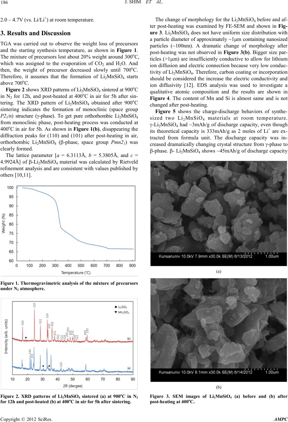 J. S HIM ET AL. Copyright © 2012 SciRes. A MPC 186 2.0 – 4.7V (vs. Li/Li+) at room temperature. 3. Results and Discussion TGA was carried out to observe the weight loss of precursors and the starting synthesis temperature, as shown in Figure 1. The mixture of precursors lost about 20% weight around 300oC, which was assigned to the evaporation of CO2 and H2O. And then, the weight of precursor decreased slowly until 700oC. Therefore, it assumes that the formation of Li2MnSiO4 starts above 700oC. Figure 2 shows XRD patterns of Li2MnSiO4 sintered at 900oC in N2 for 12h, and post-heated at 400oC in air for 5h after sin- tering. The XRD pattern of Li2MnSiO4 obtained after 900oC sintering indicates the formation of monoclinic (space group P21/n) structure (γ-phase). To get pure orthorhombic Li2MnSiO4 from monoclinic phase, post-heating process was conducted at 400oC in air for 5h. As shown in Figure 1(b), disappearing the diffraction peaks for (110) and (101) after post-heating in air, orthorhombic Li2MnSiO4 (β-phase, space group Pmn21) was clearl y formed. The lattice parameter [a = 6.3113Å, b = 5.3805Å, and c = 4.9924Å] of β-Li2MnSiO4 material was calculated by Rietveld refinement analysis and are consistent with values published by others [1 0, 11]. Figure 1. Thermogravimetric analysis of the mixture of precursors under N2 atmosphere. Figure 2. XRD patterns of Li2MnSiO4 sintered (a) at 900oC in N2 for 12h and post-heated (b) at 400oC in air for 5h after sintering. The change of morphology for the Li2MnSiO4 befor e and af- ter post-heating was examined by FE-SEM and shown in Fig- ure 3. Li2MnSiO4 does not have uniform size distribution with a particl e diameter o f app roximatel y ~1µm containing nanosized particles (~100nm). A dramatic change of morphology after post-heating was not observed in Figure 3(b). Bigger size par- ticles (>1 µm) are insufficiently conductive to allow for lithium ion diffusion and electric connection because very low conduc- tivity of Li2MnSiO4. Therefore, carbon coating or incorporation should be considered the increase the electric conductivity and ion diffusivity [12]. EDS analysis was used to investigate a qualitative atomic composition and the results are shown in Figure 4. The content of Mn and Si is almost same and is not changed after post-heat ing. Figure 5 shows the charge-discharge behaviors of synthe- sized two Li2MnSiO4 materials at room temperature. γ-Li2MnSiO4 had ~3mAh/g of discharge capacity, even though its theoretical capacity is 333mAh/g as 2 moles of Li+ are ex- tracted from formula unit. The discharge capacity was in- creased dramaticall y changin g crystal structu re from γ-ph ase to β-phase. β- Li2MnSiO4 shows ~45mAh/g of discharge capacity (a) (b) Figure 3. SEM images of Li2MnSiO4 (a) before and (b) after post-heat in g at 400oC. 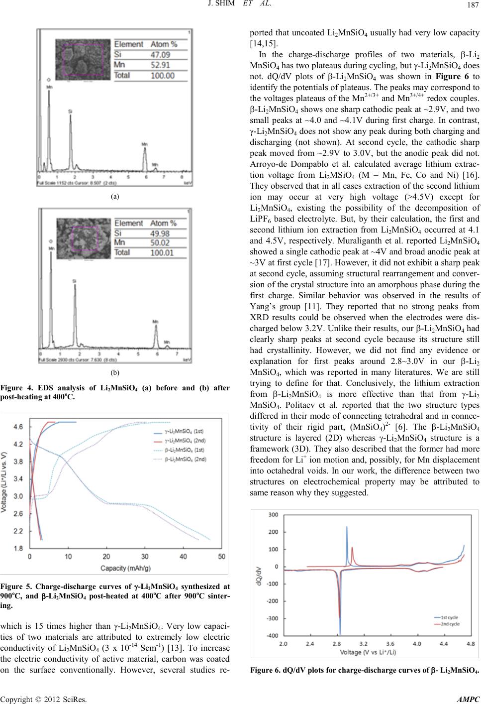 J. S HIM ET AL. Copyright © 2012 SciRes. A MPC 187 (a) (b) Figure 4. EDS analysis of Li2MnSiO4 (a) before and (b) after post-heat in g at 400oC. Figure 5. Charge-discharge curves of γ-Li2MnSiO4 synthesized at 900oC, and β-Li2MnSiO4 post-heated at 400oC after 900oC sinter- ing. which is 15 times higher than γ-Li2MnSiO4. Very low capaci- ties of two materials are attributed to extremely low electric conductivity of Li2MnSiO4 (3 x 10-14 Scm-1) [13]. To increase the electric conductivity of active material, carbon was coated on the surface conventionally. However, several studies re- ported that uncoated Li2MnSiO4 usually had very low capacit y [14,15]. In the charge-discharge profiles of two materials, β-Li2 MnSiO4 has two plateaus during cycling, but γ-Li2MnSiO4 does not. dQ/dV plots of β-Li2MnSiO4 was shown in Figure 6 to identify the potentials of plateaus. The peaks may correspond to the vol tages plateaus of th e Mn2+/3+ and Mn3+/4+ redox co uples. β-Li2MnSiO4 shows one sharp cathodic peak at ~2.9V, and two small peaks at ~4.0 and ~4.1V during first charge. In contrast, γ-Li2MnSiO4 does not show any peak during both charging and discharging (not shown). At second cycle, the cathodic sharp peak moved from ~2.9V to 3.0V, but the anodic peak did not. Arroyo-de Dompablo et al. calculated average lithium extrac- tion voltage from Li2MSiO4 (M = Mn, Fe, Co and Ni) [16]. They obser ved that in all cases extraction of the second lithium ion may occur at very high voltage (>4.5V) except for Li2MnSiO4, existing the possibility of the decomposition of LiPF 6 based electrolyte. But, by their calculation, the first and second lithium ion extraction from Li2MnSiO4 occurred at 4.1 and 4.5V, respectively. Muraliganth et al. reported Li2MnSiO4 showed a si ngle cath odic peak at ~ 4V and bro ad anodic peak at ~3V at first cycle [17]. However, it did not exhibit a sharp peak at secon d cycle, as suming struct ural rear rangemen t and conver- sion of the crystal structure into an amorphous phase during the first charge. Similar behavior was observed in the results of Yang’s group [11]. They reported that no strong peaks from XRD results could be observed when the electrodes were dis- charged below 3.2V. Unlike their results, our β-Li2MnSiO4 had clearly sharp peaks at second cycle because its structure still had crystallinity. However, we did not find any evidence or explanation for first peaks around 2.8~3.0V in our β-Li2 MnSiO4, which was reported in many literatures. We are still trying to define for that. Conclusively, the lithium extraction from β-Li2MnSiO4 is more effective than that from γ-Li2 MnSiO4. Politaev et al. reported that the two structure types differed in their mode of connecting tetrahedral and in connec- tivity of their rigid part, (MnSiO4)2- [6]. The β-Li2MnSiO4 structure is layered (2D) whereas γ-Li2MnSiO4 structure is a framework (3D). They also described that the former had more freedom for Li+ ion motion and, possibly, for Mn displacement into octahedral voids. In our work, the difference between two structures on electrochemical property may be attributed to same reason why they suggested. Figure 6. dQ/dV plots for charge-dischar g e cu rv es o f β- Li2MnSiO4. 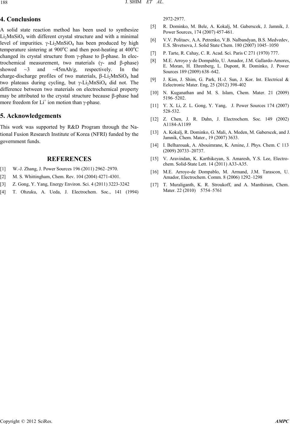 J. S HIM ET AL. Copyright © 2012 SciRes. A MPC 188 4. Conclusions A solid state reaction method has been used to synthesize Li2MnSiO4 with different crystal structure and with a minimal level of impurities. γ-Li2MnSiO4 has been produced by high temperature sintering at 900oC and then post-heating at 400oC changed its crystal structure from γ-phase to β-phase. In elec- trochemical measurement, two materials (γ- and β-phase) showed ~3 and ~45mAh/g, respectively. In the charge-discharge profiles of two materials, β-Li2MnSiO4 had two plateaus during cycling, but γ-Li2MnSiO4 did not. The difference between two materials on electrochemical property may be attributed to the crystal structure because β-phase had more freedo m for Li+ ion m oti o n than γ-phase. 5. Acknowledgements This work was supported by R&D Program through the Na- tional Fusion Research Institute of Korea (NFRI) funded by the government funds. REFERENCES [1] W.-J. Zhang, J. P ower Sources 196 (2011) 2962–2970. [2] M. S. Whittingham, Chem. Rev. 104 (2004) 4271-4301. [3] Z. Gong, Y. Yang, Energy Environ. Sci. 4 (2011) 3223-3242 [4] T. Ohzuku, A. Ueda, J. Electrochem. Soc., 141 (1994) 2972-2977. [5] R. Dominko, M. Bele, A. Kokalj, M. Gaberscek, J. Jamnik, J. Power Sources, 174 (2007) 457-461. [6] V.V. Politaev, A.A. Petrenko, V.B. Nalbandyan, B.S. Medvedev, E.S. Shvetsova, J. Solid State Chem. 180 (2007 ) 1045–1050 [7] P. Tarte, R. Cahay, C. R. Acad. Sci. Paris C 271 (1970) 777. [8] M.E. Arroyo y de Dompablo, U. Amador, J.M. Gallardo-Amores, E. Moran, H. Ehrenberg, L. Dupont, R. Dominko, J. Power Sources 189 (2009) 638–642. [9] J. Kim, J. Shim, G. Park, H.-J. Sun, J. Kor. Int. Electrical & Eelectronic Mater. En g, 25 (2012) 398-402 [10] N. Kuganathan and M. S. Islam, Chem. Mater. 21 (2009) 5196–5202. [11] Y. X. Li, Z. L. Gong, Y. Yang, J. Power Sources 174 (2007) 528-532. [12] Z. Chen, J. R. Dahn, J. Electrochem. Soc. 149 (2002) A1184-A1189 [13] A. Kokalj, R. Dominko, G. Mali, A. Meden, M. Gaberscek, and J. Jamnik, Chem. Mater., 19 (2007) 3633. [14] I. Belharouak, A. Abouimrane, K. Amine, J. Phys. Chem. C 113 (2009) 20733–20737. [15] V. Aravindan, K. Karthikeyan, S. Amaresh, Y.S. Lee, Electro- chem. Solid-State Lett. 14 (2011) A33-A35. [16] M.E. Arroyo-de Dompablo, M. Armand, J.M. Tarascon, U. Amador, Electroc hem. Comm. 8 (2006) 1292–1298 [17] T. Muraliganth, K. R. Stroukoff, and A. Manthiram, Chem. Mater. 22 (2010) 5754–5761 |