Paper Menu >>
Journal Menu >>
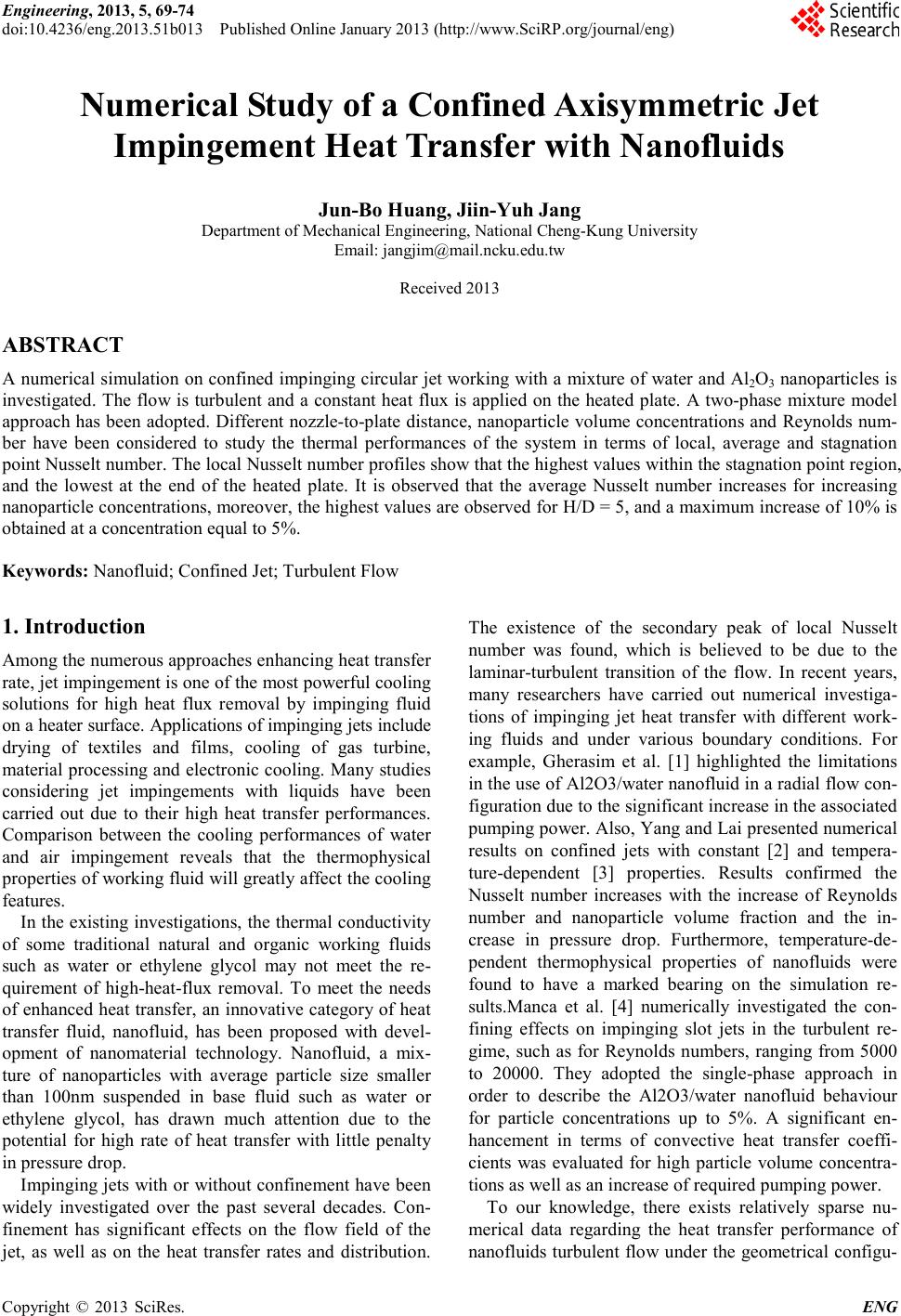 Engineering, 2013, 5, 69-74 doi:10.4236/eng.2013.51b013 Published Online January 2013 (http://www.SciRP.org/journal/eng) Copyright © 2013 SciRes. ENG Numerical Study of a Con f ined Axisymmet ri c Jet Impingement Heat Transfer with Nanofluids Jun-Bo Huang, Jiin-Yuh Jang Department of Mechanical Engineering, National Cheng-Kung University Email: jangj im@mail.ncku .edu.tw Received 2013 ABSTRACT A nume rical si mulatio n on conf ined imp inging ci rcular jet worki ng with a mixture of wate r and Al2O3 nanop articles is investigated. The flow is turbulent and a constant heat flux is applied on the heated plate. A two-phase mixture model approach has been adopted. Different nozzle-to-plate distan ce, nanoparticle volume concentrations and Reynolds num- ber have been considered to study the thermal performances of the system in terms of local, average and stagnation point Nusselt number. T he local Nusselt n umber p r ofi les s how t ha t t he hi g hest va l ue s wit hi n the s tag na tion p o int re gion, and the lowest at the end of the heated plate. It is observed that the average Nusselt number increases for increasing nanoparticle concentrations, moreover, the highest values are observed for H/D = 5, and a maximum increase of 10% is obtained at a concentration equal to 5%. Keywords: Nanofluid; Confined J et; Turbulent Flow 1. Introduction Among the numerous approaches enhancing heat transfer rate, j et impingement is o ne of the most powerful cooling solutions for high heat flux removal by impinging fluid on a heater surface. Applications of impinging jets include drying of textiles and films, cooling of gas turbine, material processing and electronic cooling. Many studies considering jet impingements with liquids have been carried out due to their high heat transfer performances. Comparison between the cooling performances of water and air impingement reveals that the thermophysical prop erties of working fluid will greatl y affect the cooling features. In the e xistin g invest igation s, the t hermal co nducti vity of some traditional natural and organic working fluids such as water or ethylene glycol may not meet the re- quirement of high-heat-flux removal. To meet the needs of enhanced heat transfer, an innovative category of heat transfer fluid, nanofluid, has been proposed with devel- opment of nanomaterial technology. Nanofluid, a mix- ture of nanoparticles with average particle size smaller than 100nm suspended in base fluid such as water or ethylene glycol, has drawn much attention due to the potential for high rate of heat transfer with little penalty in pressure drop. Impi nging je ts with o r witho ut confi nement ha ve bee n widely investigated over the past several decades. Con- finement has significant effects on the flow field of the jet, as well as on the heat transfer rates and distribution. The existence of the secondary peak of local Nusselt number was found, which is believed to be due to the laminar -turbulent transition of the flow. In recent years, many researchers have carried out numerical investiga- tions of impinging jet heat transfer with different work- ing fluids and under various boundary conditions. For example, Gherasim et al. [1] highlighted the limitations in the use of Al2O3 /water nan ofluid in a rad ial flo w con- figura ti o n d ue to the significant increase in the associated pumping power. Also, Yang and Lai presented numerical results on confined jets with constant [2] and tempera- ture-dependent [3] properties. Results confirmed the Nusselt number increases with the increase of Reynolds number and nanoparticle volume fraction and the in- crease in pressure drop. Furthermore, temperature-de- pendent thermophysical properties of nanofluids were found to have a marked bearing on the simulation re- sults.Manca et al. [4] numerically investigated the con- fining effects on impinging slot jets in the turbulent re- gime, such as for Reynolds numbers, ranging from 5000 to 20000. They adopted the single-phase approach in order to describe the Al2O3/water nanofluid behaviour for particle concentrations up to 5%. A significant en- hancement in terms of convective heat transfer coeffi- cients was evaluated for high particle volume concentra- tions as well as an increase of required pumping power. To our knowledge, there exists relatively sparse nu- merical data regarding the heat transfer performance of nanofluids turbulent flow under the geometrical configu-  J.-B. HUANG, J.-Y. JANG Copyright © 2013 SciRes. ENG 70 ration of a confined impinging jet. In the present paper, Al2O3-water nanofluids are introduced into confined sin- gle ci rcula r je t impinge ment coo ling s ystem a s the work- ing fluid. The objective of this work is to numerically investigate the impingement heat transfer features of the nanofluids. The effects of the nanoparticle concentration, Reynolds number and nozzle-to-plate distance on the heat transfer and flow performances of the nanfluids for the jet impingement are discussed. The results are ex- pected to be valuable toward the design of cooling sys- tem for e ngineering ap plications. 2. Geometrical Configuration An axisymmetric turbulent confined jet impinging on a flat plate with constant heat flux has been analyzed nu- merically. A geometrical configuration used in the analy- sis is shown in Figure 1. Because of axisymmetric, si- mulation of only a half-doma in is adequate for com- plete characterization of the flow. The jet orifice diame- ter D is 2mm. The geo metrical c onfiguration has a radius R equal to 16 mm and the nozzle-to-plate distance H/D ranging from 1 to 5. 3. Mathmatical Method 3.1. Mixture Model For incompressible steady flow, the continuity equation for the mixtur e is: 0= ⋅∇ → m m v ρ (1) The momentum equation for the mixture can be ex- pressed as: +⋅∇+ ⋅∇+−∇= ⋅∇ →→→→ →→→ sdrsdr ss pdrpdr pp mmm m vvvv pvv ,,,, ραρα τρ (2) ( ) →→→→ − ∇+∇+= Ikvv mm T mm mtm m ρµµτ 3 2 , (3) The energy equation for the mixt ure is: ( ) TTvcTvc meff s spss p pppp ∇⋅∇= +⋅∇ →→ ,,, λραρα (4) D H Jet Confined wallConfined wall Impingement Surface Pressure Outletyr Figure 1. Sketch of the geometrical model. m ρ is the mixture density defined as : ssppm ραραρ += (5) m v → is the mas s-averaged mixture velocity : m s ss p pp m vv v ρ ραρα →→ → + = (6) p α and s α are the volume fractions of the primary and the secondary phases, respectively. p ρ and s ρ are the densitie s of t he primary and the secondary phases, re- spectively. , pp c and ,ps c are the specific heat of the pri- mary and the secondary phases, respectively. ,eff m λ is the effective thermal conductivity. The viscosity of the mi xtur e m µ is defined as: ssppm µαµαµ += (7) where p µ and s µ are the viscosities of the primary phase and the secondary phase, respectively. The drift velocity for the secondary phase ,dr s v → is defined as the velocity of the dispersed phase relative to that of the mixtur e ve lo city: mssdr vvv →→→ −= , (8) The slip of the secondary dispersed phase relative to continuous phase is calculated by balancing the drag and body forces resulting from density differences. The rela- tive velocity sp v → is defined as the velocit y of the second- dary phase relative to the pri mary phase velocity. pssp vvv →→→ −= (9) The dr ift velocity is related to the relati ve velo c ity: sp m ss spsdr vvv →→→ −= ρ ρα , (10) The relative velocity is calculated by: ( ) →→ − =a f d v Dp sms sp µ ρρ 18 2 (11) where s d is the diameter of the particles of secondary phase and a → is the secondary phase particle accelera- tion. T he drag functio n D f is given by: 24 Re D D C f= (12) There are several correlations that fit the drag coeffi- cient as a function of Reynolds number available in the literature. The general form used in this study is given by: 2 32 1Re Re aa aCD++= (13) where a1, a2 and a3 are sets of constants that apply over various range of Reynolds number.  J.-B. HUANG, J.-Y. JANG Copyright © 2013 SciRes. ENG 71 The acceleration a → is given by: t v vvga m mm ∂ ∂ − ∇⋅−= → →→→→ (14) From the continuity equation for the secondary phase, the volume fraction equation for the secondary phase is: −∇= ∇ →→ sdr ss m ss vv , ραρα (15) 3.2. Turbulence Modeling Previous studies have shown that the heat transfer simu- lation of turbulent confined jet flow configuration is quite co mplex. A suitable turb ulence model is re quired to predict the flow and thermal structure with reasonable accuracy. This is required to minimize the error associ- ated with turbulence modeling and enables the investiga- tion of the mixture model. A comparison between the results obtained by using different turbulence models has shown that a k-ω based shear stress transport (SST) model developed by Menter [8] is the appropriate model to determine the local wall Nusselt number for this kind of flow co n figura tion. The k-ω SST model include the addition of a cross-diffusio n ter m in the ω equat ion a nd a blending function to ensure that the model equations be- have appropriately in both the near-wall and far-field zones. It has been shown to be quite adequate for appli- cations with separating flows. This turbulence model is used in the present work. The transport equations for SST k ω − are: kk k t m m YGkkv−+ ∇ +∇= ⋅∇ → σ µ µρ (16) ωωω ω ω σ µ µωρ DYGv t m m +−+ ∇ +∇= ⋅∇ → (17) In Eqs. (16) and (17), Gk represents the generation of the turbulent kinetic energy k, due to mean velocity gra- dients, and Gω represents the generation of the specific dissipation rate ω. Yk and Yω represents the dissipa tion of k and ω due to turbulence. Dω is a cr oss-diffusion term . 3.3. Boundary Conditions The bo undary conditions are expressed as follows: Inlet section: Uniform temperature equal to 300K and different uniform velocities, corresponding to Reynolds number ranging from 5000 to 30000 are considered. Furthermore, the inlet turbulence intensit y value is set to 2%. Outlet section: pressure outlet boundary condition is specified. Botto m wall: T he no-slip boundary condition is imposed on the target plate that i s ke pt at const ant hea t fl ux o f 5 x 10⁵W/m2. Upper wall: The no-slip boundary condition is imposed on the confinement surface that is considered to be an adiabatic wall. The axis-symmetric boundary condition is applied along the line of axis-symme tr ic. The working fluid is water or a mixture of water and Al2O3 nanoparticles at different volume fractions equal to 1, 3 and 5%. 3.4. Physical Properties of Nanof luids The following equations are used to evaluate the effect- tive prope rties of the nano fluid. Density: ( ) pfnf φρρφρ +−= 1 (18) Specific heat: ( ) pppfpfnfpnf ccc ,,, 1 φρρφρ +−= (19) Viscosity: ( ) fnf µφφµ 13.7123 2 ++= (20) This was presented by the Maiga et al. [9] for water- Al2O3 nanofluid based on available experimental results in the literature. Thermal conductivity: ( ) fnf kk 172.297.4 2 ++= φφ (21) 3.5. Dimens ionl ess Para m eter s The dimensionless parameters considered here are: µ ρ VD =Re (22) k D TT q k hD Nu fs − == " (23) The local Nusselt number distribution is averaged to obtain an average Nusselt number. The average Nusselt number is defined as ∫⋅⋅== R o drrNu R k Dh Nu 2 2 (24) 3.6. Numerical Procedure The computational fluid dynamic code FLUENT was employed to solve the present problem. The governing equations of continuity, momentum and energy were solve d by the fi ni te vo l u me me tho d . A QUICK scheme is chosen for momentum and energy equations. The SIM- PLE algorithm was chosen as scheme to couple pressure and velocity. The discretization grid is finer near the wall where the velocity and temperature gradients are signifi-  J.-B. HUANG, J.-Y. JANG Copyright © 2013 SciRes. ENG 72 cant. The convergence criteria of 10-5 for the resid uals o f the velocity components and of 10-6 for the residuals of the energy are specified. 4. Results and Discussion The local Nusselt number distributions for H/D= 2 are sho wn in F ig ure 2. T he local Nusselt numbers at the first peaks (Nu1st) are approximately 7% - 10% higher than the stagnation point values (Nu0) for all the cases considered in the paper. The first peak values of the 8% nanofluid jet are about 5% - 6% higher than the stagnation point values of the water jet. However, the local Nusselt numbers at the second peaks (Nu2nd) are approximately 2% - 14% less than the stagnation point values. The ratio of Nu2nd/Nu1st is weakly dependent on the jet Reynolds number. These results indicate that the heat transfer mechanism between these two peaks is nearly independent of the jet Reynolds number. The first peaks in local Nusselt number distributions correspond- ing to the maximum heat transfer rates occur at r/D~0.5 of the orifice noz zles. T he first p eak is stron gly attr ibuted to the high turbulence intensity at the nozzle edge. The secondary peaks occur in the range of 1.4<r/D<1.9 fo r a l l nozzle configurations and Reynolds numbers tested. The local heat transfer distributions for the nozzle- to-plate spacing of H/D = 5 are shown in F igure 3. The local Nusselt numbers decrease monotonically and do not show the secondary maxima at all. For all the cases con- ducted in the paper, the local heat transfer distributions show nearly similar shapes in the wall jet region. In the stag natio n regio n, the 5% nanofluid jets have highe r hea t transfer rates than the other jets. The stagnation point r / D Nu 01234 100 150 200 250 Pure Water 1% Nanofluid 3% Nanofluid 5% Nanofluid H/D=2, Re=20000 Figure 2. Local Nusselt number distribution at the nozzle- to-plate s pacing of H/D=2. r / D Nu 01234 100 150 200 250 Pure Water 1% Nanofluid 3% Nanofluid 5% Nanofluid H/D=5, Re=20000 Figure 3. Local Nusselt number distribution at the nozzle- to-plate s pacing of H/D=5. Re Nuo 10000 20000 30000 100 150 200 250 300 Pure Water Nanofluid 1% Nanofluid 3% Nanofluid 5% H/D=2 Figure 4. Various of stagnation point Nusse lt numbers with Reynolds number at H/D=2. Nusselt numbers of the 5% nanofluid jet are approx- imately 7-9% higher than those of the water jet. Fur- the rmore, in the transition and wall jet regions, the local heat transfer rates of the nanofluid jet with different vo- lume fraction of nanoparticles are higher than the pure water jet. For high H/D values, local Nusselt number decreases more slowly than high H/W r atios. The effects of volume fraction of nanoparticles on the stagnation point heat transfer are shown in Figure 4 and Figure 5 as functio n o f je t Re ynold s n umbe r. I t is sho wn how the variation of nanofluid concentration affects the heat transfer. The Reynolds number dependency of the 5% nanofluid jet is larger than that of the water jet at H/D = 2. The effect of volume fraction of nanoparticles on the stagnation point heat transfer is more sensible at shorter nozzle-to-plate spacing. The present Nu0 data of 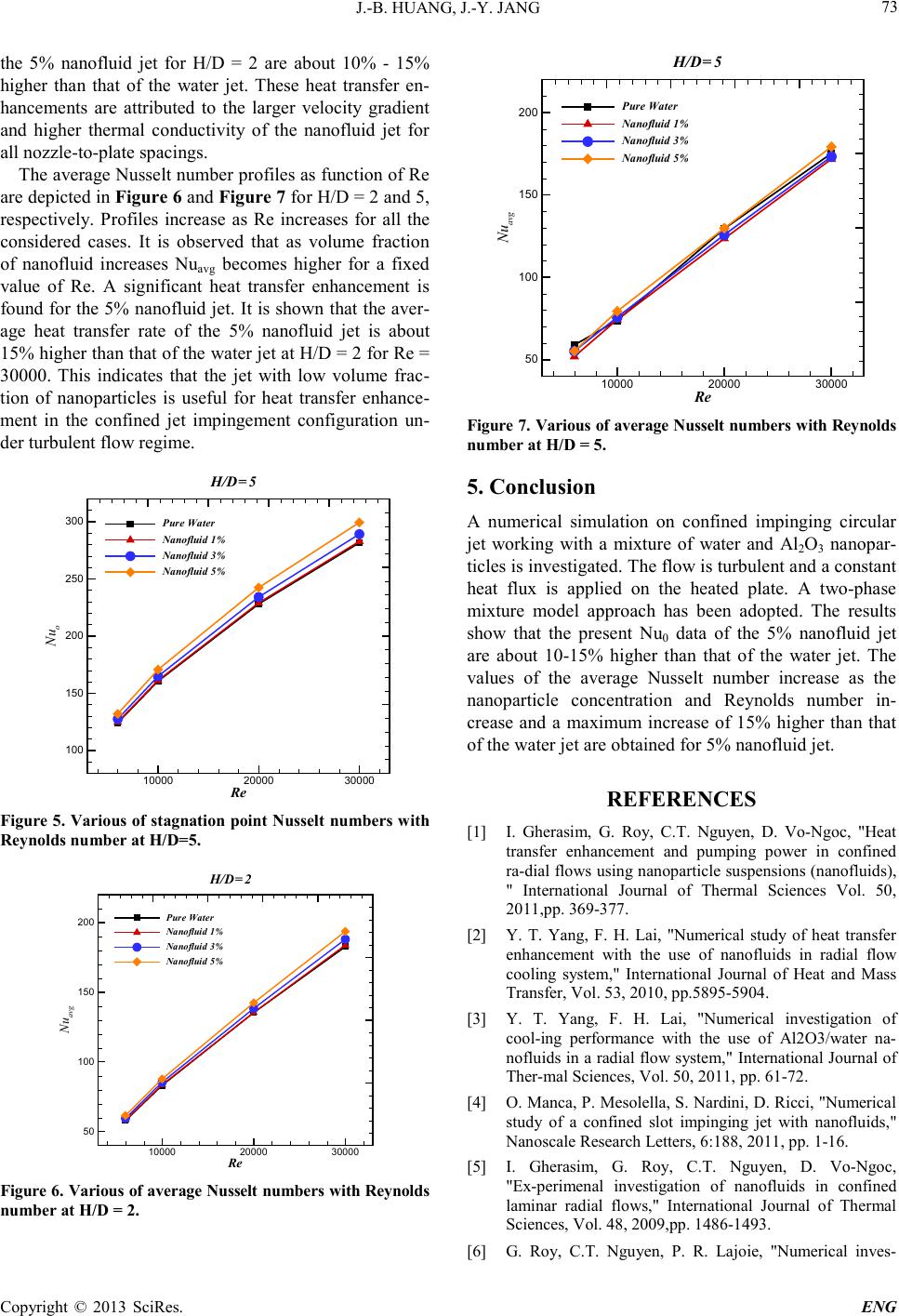 J.-B. HUANG, J.-Y. JANG Copyright © 2013 SciRes. ENG 73 the 5% nanofluid jet for H/D = 2 are about 10% - 15% higher than that of the water jet. These heat transfer en- hancements are attributed to the larger velocity gradient and higher thermal conductivity of the nanofluid jet for all nozzle-to-plate spacings. The average Nusselt number profiles as function of Re are depicted in Figure 6 and Figure 7 for H/D = 2 a nd 5, respectively. Profiles increase as Re increases for all the considered cases. It is observed that as volume fraction of nanofluid increases Nuavg becomes higher for a fixed value of Re. A significant heat transfer enhancement is found for the 5% nanofluid jet. It is shown that t he aver- age heat transfer rate of the 5% nanofluid jet is about 15% higher than that o f the water je t at H/D = 2 for Re = 30000. This indicates that the jet with low volume frac- tion of nanoparticles is useful for heat transfer enhance- ment in the confined jet impingement configuration un- der turbulent flow re gime. Re Nu o 10000 20000 30000 100 150 200 250 300 Pure Water Nanofluid 1% Nanofluid 3% Nanofluid 5% H/D=5 Figure 5. Various of stagnati on point N usselt numbers w ith Reynolds number at H/D=5. Re Nu avg 10000 20000 30000 50 100 150 200 Pure Water Nanofluid 1% Nanofluid 3% Nanofluid 5% H/D=2 Figure 6. Various of aver age Nusselt nu mbe rs with Rey nolds number at H/ D = 2. Re Nu avg 10000 20000 30000 50 100 150 200 Pure Water Nanofluid 1% Nanofluid 3% Nanofluid 5% H/D=5 Figure 7. Various of a verage N usselt numbers w ith Rey nolds number at H/ D = 5. 5. Conclusion A numerical simulation on confined impinging circular jet working with a mixture of water and Al2O3 nanopar- ticles is investi gated. T he flow is turbule nt and a constant heat flux is applied on the heated plate. A two-phase mixture model approach has been adopted. The results show that the present Nu0 data of the 5% nanofluid jet are about 10-15% higher than that of the water jet. The values of the average Nusselt number increase as the nanoparticle concentration and Reynolds number in- crease and a maximum increase of 15% higher than that of the water jet are obtained for 5% nanofluid jet. REFERENCES [1] I. Gherasim, G. Roy, C.T. Nguyen, D. Vo-Ngoc, "Heat transfer enhancement and pumping power in confined ra-dial flows using nanoparticle suspensions (nanofluids), " International Journal of Thermal Sciences Vol. 50, 2011,pp. 369-377. [2] Y. T. Yang, F. H. Lai, "Numerical study of heat transfer enhancement with the use of nanofluids in radial flow cooling system," International Journal of Heat and Mass Tra nsfer, Vol. 53 , 2010, pp.5 895-5904. [3] Y. T. Yang, F. H. Lai, "Numerical investigation of cool-ing performance with the use of Al2O3/water na- nofluids in a radial flow system," International Journal of Ther-mal Sciences, Vol. 50, 2011, p p. 61-72. [4] O. M anca, P. Meso lella, S. Nardini, D. Ricci, "Numerical study of a confined slot impinging jet with nanofluids," Nanoscale Research Letters, 6:188, 2011 , pp. 1-16. [5] I. Gherasim, G. Roy, C.T. Nguyen, D. Vo-Ngoc, "Ex-perimenal investigation of nanofluids in confined laminar radial flows," International Journal of Thermal Scie nc e s , Vol. 48, 2009,p p. 1486-1493. [6] G. Roy, C.T. Nguyen, P. R. Lajoie, "Numerical inves-  J.-B. HUANG, J.-Y. JANG Copyright © 2013 SciRes. ENG 74 ti-gation of laminar flow and heat transfer in a radial flow cooling system with the use of nanofluids," Superlattices and Microstructures, Vol. 35, 2004, pp. 497-511. [7] G. Roy, I. Gherasim, F. Nadeau, G. Poitras, C. T. Nguyen, “Heat transfer performance and hydrodynamic behavior of turbulent nanofluid radial flows,” International Jour-nal of Thermal Sciences, Vol. 58, 2012,pp. 120-129. [8] F. Menter, Two-equation eddy-viscosity turbulence mod- els for engineering applications, AIAA J., 32 (8), 1994, pp. 1598 -1605. [9] S.E.B. Maiga, N. Cong Tam, N. Galanis, G. Roy, T. Mar e, M. Coqueux, “Heat transfer enhancement in turbulent tube flow using Al2O3 nanoparticle suspension,” In- ter-national Journal of Numerical Methods Heat Fluid Flow, Vol. 16, 2006, pp. 275-292. [10] S.J. Palm, G. Roy, C.T. Nguyen, “Heat transfer en-hancement with the use of nanofluids in radial flow cool-ing systems considering temperature dependent properties,” Applied Thermal Engineering, Vol. 26, 2006, pp. 2209 -2218. [11] M. Manninen, V. Taivassalo, S. Kallio, On the Mixture Model for Multiphase Flow, VTT Publica-tions 288, Technical Research Centr e of Finlan d, 1996. |