Paper Menu >>
Journal Menu >>
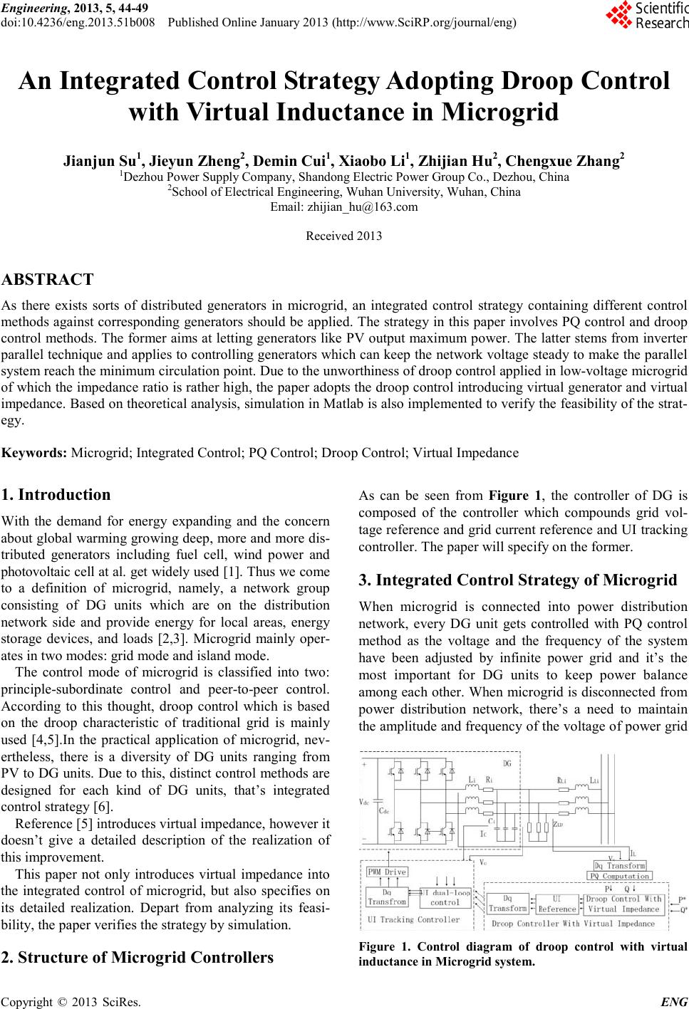 Engineering, 2013, 5, 44-49 doi:10.4236/eng.2013.51b008 Published Online January 2013 (http://www.SciRP.org/journal/eng) Copyright © 2013 SciRes. ENG An Integrated Control Strategy Adopt ing Droop Control with Virtual Inductance in Microgrid Jianjun Su1, Jieyun Zhe ng 2, Demin Cui1, Xiaobo Li1, Zhijian Hu2, Chengxue Zhang2 1Dezhou Power Supply Company, Shandong Electric Power Group Co., Dezhou, China 2Scho ol of Electri cal Engineering, Wuhan University, Wuhan, China Email: zhijian_hu@163.com Received 2013 ABSTRACT As there exists sorts of distributed generators in microgrid, an integrated control strategy containing different control methods against corresponding generators should be applied. The strategy in this paper involves PQ control and droop control methods. The former aims at letting ge nerato rs like P V output maxi mu m power. T he latter stems from inverter parallel technique and app lies to controlling generators which can keep the network voltage steady to make the parallel system rea ch t he mini mu m ci r c ula tio n p o int. Due to the unworthiness of droop control applied in low-voltage microgrid of which the impedance ratio is rather high, the paper adopts the d ro op contr ol i ntro duci ng vi rtual ge ner ator and vir tual impedance. Based on theore tical anal ysis, simulatio n in Matlab is also implemented to verify the feasibilit y of the strat- egy. Keywords: Microgrid; Integrated Control; PQ Control; Droop Control; Virtual Impedance 1. Introduction With the demand for energy expanding and the concer n about global warming growing deep, more and more dis- tributed generators including fuel cell, wind power and photovo ltaic ce ll at al. get wid ely used [1] . Thus we come to a definition of microgrid, namely, a network group consisting of DG units which are on the distribution network side and provide energy for local areas, energy storage devices, and loads [2,3]. Microgrid mainly oper- ates in two modes: grid mode and island mode. The control mode of microgrid is classified into two: principle-subordinate control and peer-to-peer control. According to this thought, droop control which is based on the droop characteristic of traditional grid is mainly used [4,5].In the practical application of microgrid, nev- ertheless, there is a diversity of DG units ranging from PV to DG unit s. Due to this, distinct co ntrol methods are designed for each kind of DG units, that’s integrated control strate gy [6]. Reference [5] introduces virtual impedance, however it doesn’t give a detailed description of the realization of this improve ment. This paper not only introduces virtual impedance into the integrated control of microgrid, but also specifies on its detailed realization. Depart from analyzing its feasi- bility, the paper verifies the strategy b y simulation. 2. Structure of Microgrid Controllers As can be seen from Figure 1, the controller of DG is composed of the controller which compounds grid vol- tage reference and grid current reference and UI tracking controller. The pape r will specify on the former. 3. Integrated Control Strategy of Microgrid When microgrid is connected into power distribution network, every DG unit gets controlled with PQ control method as the voltage and the frequency of the system have been adjusted by infinite power grid and it’s the most important for DG units to keep power balance among each other. When microgrid is disconnected from power distribution network, there’s a need to maintain the a mpli tud e and freq uenc y o f t he vol tage o f po wer gr id Figure 1. Control diagram of droop control with virtual inductance in Microgrid system. 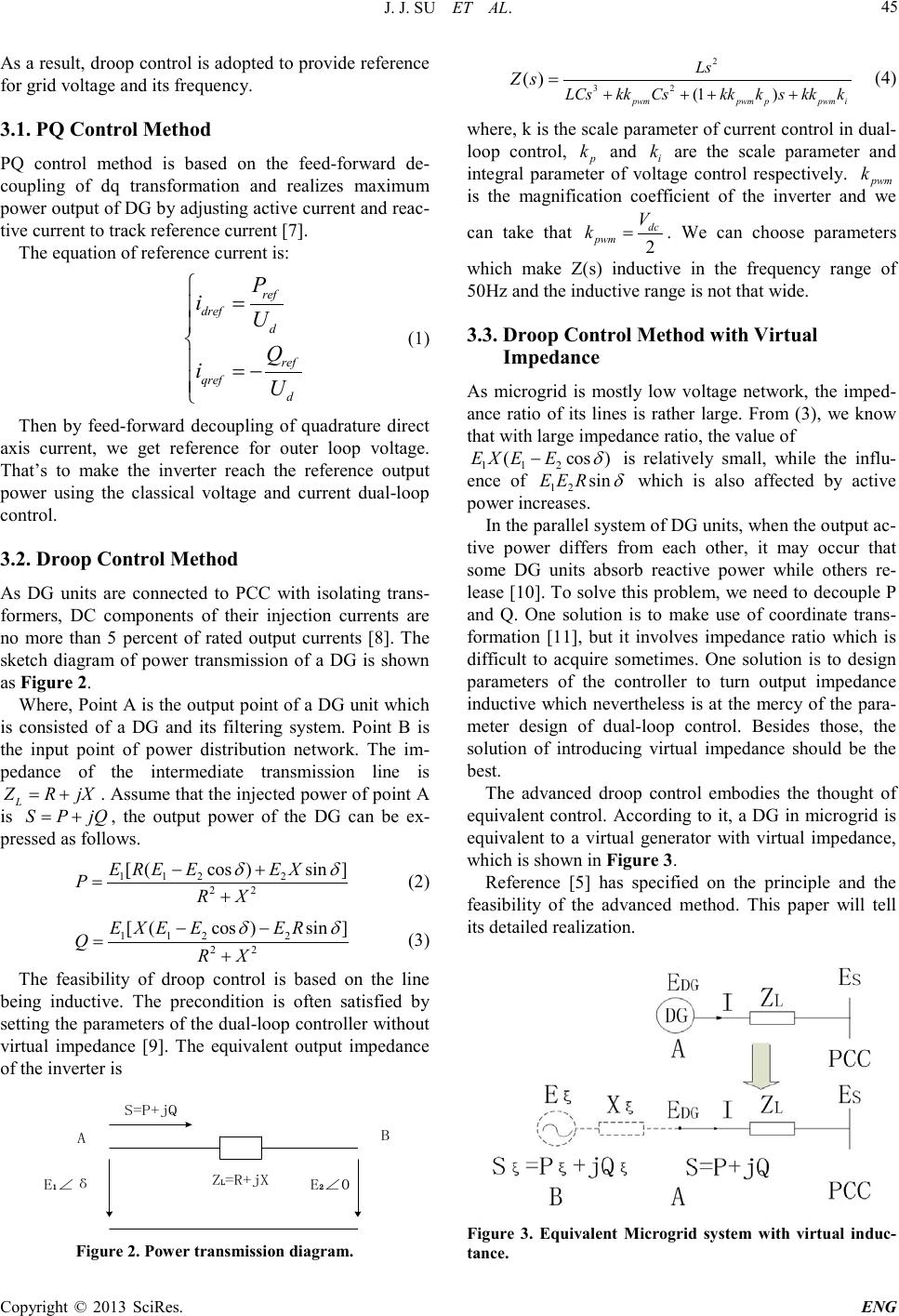 J. J. SU ET AL. Copyright © 2013 SciRes. ENG 45 As a result, droop control is adopted to provide reference for grid volta ge a nd its frequenc y. 3.1. PQ Control Method PQ control method is based on the feed-forward de- coupling of dq transformation and realizes maximum power output of DG by adjusting active current and reac- tive current to track reference current [7]. The equation of reference current is: ref dref d ref qref d P iU Q iU = = − (1) Then by feed-forward decoupling of quadrature direct axis current, we get reference for outer loop voltage. That’s to make the inverter reach the reference output power using the classical voltage and current dual-loop control. 3.2. Droop Control Method As DG units are connected to PCC with isolating trans- formers, DC components of their injection currents are no more than 5 percent of rated output currents [8]. The sketch diagram of power transmission of a DG is shown as Figure 2. Where, P oint A is the output point of a DG unit whic h is consisted of a DG and its filtering system. Point B is the input point of power distribution network. The im- pedance of the intermediate transmission line is L ZR jX= +. Assume that the injected power of point A is SP jQ= + , the output power of the DG can be ex- pressed as fo l l ows. 1 122 22 [ (cos)sin]E REEEX PRX δδ −+ =+ (2) 1 122 22 [(cos )sin]E XEEER QRX δδ −− =+ (3) The feasibility of droop control is based on the line being inductive. The precondition is often satisfied by setting the parameters of the dual-loop c ontroller without virtual impedance [9]. The equivalent output impedance of the inverter is AB S=P+jQ Z L =R+jX E 1 ∠δ E 2 ∠0 Figure 2 . Power trans mission di agram. 2 32 (1 ) () pwmpwmppwm i Ls LCskkCskk kskk k Zs + +++ = (4) where, k is the scale parameter of current control in dual- loop control, p k and i k are the scale parameter and integral parameter of voltage control respectively. pwm k is the magnification coefficient of the inverter and we can take that 2 dc pwm V k=. We can choose parameters which make Z(s) inductive in the frequency range of 50Hz and the i nductive ra nge is not that wide . 3.3. Droop Control Method with Virtual Impedance As microgrid is mostly low voltage network, the imped- ance ratio of its lines is rather large. From (3), we know that with large impedance ratio, the value of 1 12 (cos )EX EE δ − is relatively small, while the influ- ence of 12 sinEER δ which is also affected by active power increases. In the parallel s ystem o f DG units, whe n the o utput ac- tive power differs from each other, it may occur that some DG units absorb reactive power while others re- lease [10]. To solve this problem, we need to decouple P and Q. One solution is to make use of coordinate trans- formation [11], but it involves impedance ratio which is difficult to acquire sometimes. One solution is to design parameters of the controller to turn output impedance inductive which nevertheless is at the mercy of the para- meter design of dual-loop control. Besides those, the solution of introducing virtual impedance should be the best. The advanced droop control embodies the thought of equivalent control. According to it, a DG in microgrid is equivalent to a virtual generator with virtual impedance, which is sho wn in Figure 3. Reference [5] has specified on the principle and the feasibility of the advanced method. This paper will tell its detailed r e a liz a tion. Figure 3. Equivalent Microgrid system with virtual induc- tanc e . 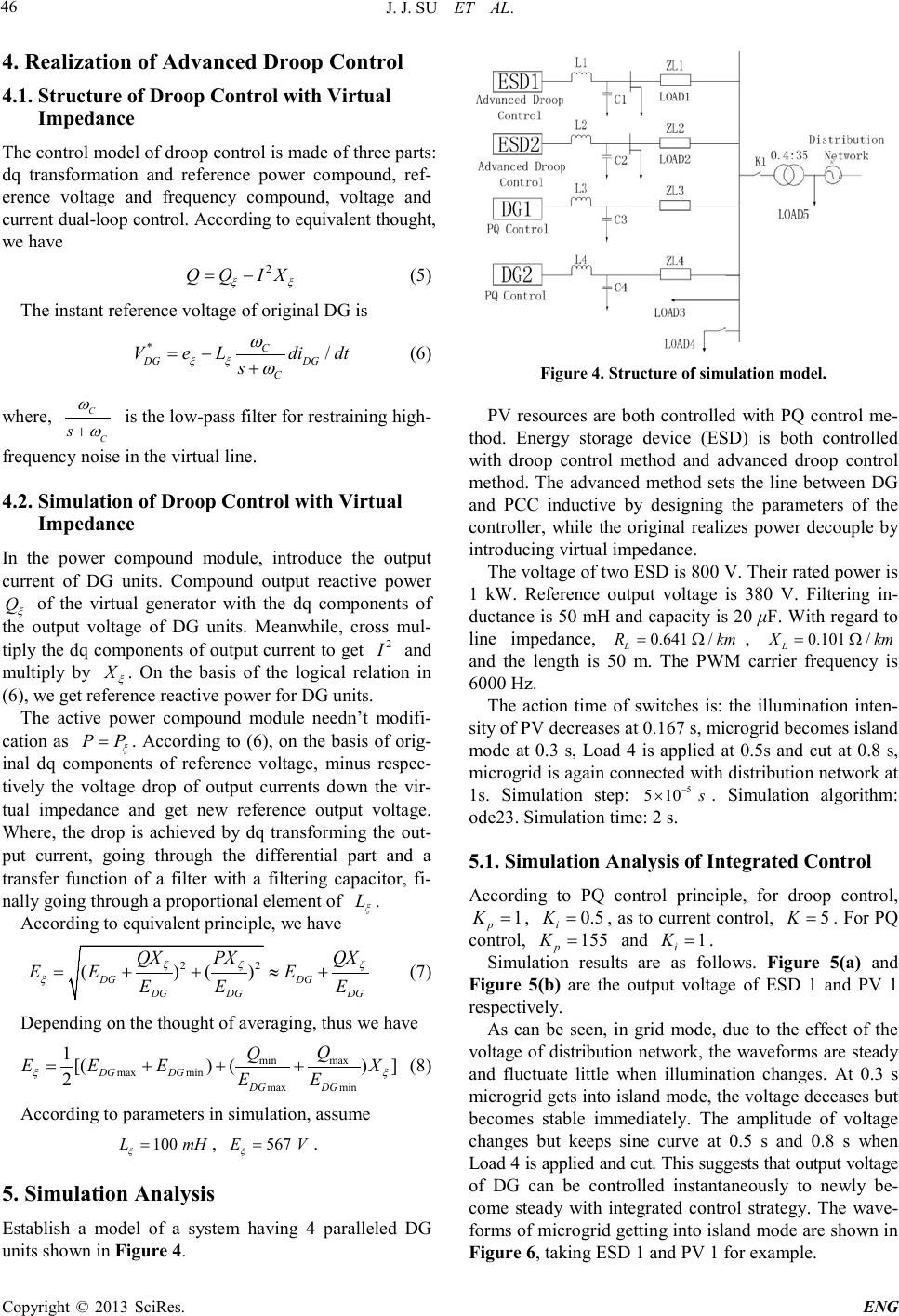 J. J. SU ET AL. Copyright © 2013 SciRes. ENG 46 4. Realization of Advanced Droop Control 4.1. Structure of Droop Control with Virtual Impedance The control model of droop control is made of three parts: dq transformation and reference power compound, ref- erence voltage and frequency compound, voltage and curr ent dua l-loop co ntro l. According to equivalent thought, we have 2 Q QIX ξξ = − (5) The instant reference voltage of original DG is */ C DG DG C Ve Ldidt s ξξ ω ω = −+ (6) where, C C s ω ω + is the low-pass filter for re straining high- freq uenc y noise in the virt ual line . 4.2. Simulation of Droop Control with Virtual Impedance In the power compound module, introduce the output current of DG units. Compound output reactive power Q ξ of the virtual generator with the dq components of the output voltage of DG units. Meanwhile, cross mul- tiply the dq components of output current to get 2 I and multiply by X ξ . On the basis of the logical relation in (6), we get reference reactive power for DG units. The active power compound module needn’t modifi- cation as PP ξ = . According to (6), on the basis of orig- inal dq components of reference voltage, minus respec- tively the voltage drop of output currents down the vir- tual impedance and get new reference output voltage. Where, the drop is achieved by dq transforming the out- put current, going through the differential part and a transfer function of a filter with a filtering capacitor, fi- nally going t hrough a p roportional el ement of L ξ . According to equi valent princi ple, we have 22 ()( ) DG DG DG DGDG QX PXQX EE E EE E ξξ ξ ξ = ++≈+ (7) Dep ending on the t hought o f averaging, thus we have max min max minmax min 1[() ()] 2 DG DGDG DG Q Q EE EX EE ξξ =++ + (8) According to parameters in simulation, assume 100 L mH ξ = , 567 EV ξ = . 5. Simulation Analysis Establish a model of a system having 4 paralleled DG units shown in Figure 4. Figure 4 . S tructure of simulati on model. PV resources are both controlled with PQ control me- thod. Energy storage device (ESD) is both controlled with droop control method and advanced droop control method. The advanced method sets the line between DG and PCC inductive by designing the parameters of the controller, while the original realizes power decouple by introduc ing virtual impedance. The voltage of two ESD is 800 V. Their rated power is 1 kW. Reference output voltage is 380 V. Filtering in- ductance is 50 mH and capacity is 20 μF. With regard to line impedance, 0.641 / L R km= Ω , 0.101 / L X km=Ω and the length is 50 m. The PWM carrier frequency is 6000 Hz. The action time of switches is: the illumination inten- sity of PV decreases at 0.167 s, microgrid becomes island mode at 0.3 s, Load 4 is applied at 0.5s and cut at 0.8 s, microgrid is again con nected with distributio n network at 1s. Simulation step: 5 5 10 s − × . Simulation algorithm: ode23. Simulation time: 2 s. 5.1. Simulation Analysis of Integrated Control According to PQ control principle, for droop control, 1 p K= , 0.5 i K= , as to current control, 5K= . For P Q control, 155 p K= and 1 i K= . Simulation results are as follows. Figure 5(a) and Figure 5(b) are the output voltage of ESD 1 and PV 1 respectively. As can be seen, in grid mode, due to the effect of the voltage of distribution network, the waveforms are steady and fluctuate little when illumination changes. At 0.3 s microgrid get s into island mode, the voltage deceases but becomes stable immediately. The amplitude of voltage changes but keeps sine curve at 0.5 s and 0.8 s when Load 4 is applied and cut. Th is s ugge sts t hat o utp ut vo ltage of DG can be controlled instantaneously to newly be- come steady with integrated control strategy. The wave- forms of microgrid getting into island mode are shown in Figure 6, taking ESD 1 and PV 1 for example. 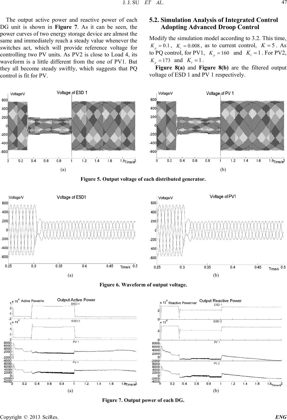 J. J. SU ET AL. Copyright © 2013 SciRes. ENG 47 The output active power and reactive power of each DG unit is shown in Figure 7. As it can be seen, the power curves of two energy storage device are almost the same and immediately reach a steady value whenever the switches act, which will provide reference voltage for controlling two PV units. As PV2 is close to Load 4, its waveform is a little different from the one of PV1. But they all become steady swiftly, which suggests that PQ control is fit for PV. 5.2. Simulation Analysis of Integrated Control Adopting Advanced Droop Control Modify the simulation mod el acco rd ing to 3.2 . T his time, 0.1 p K= , 0.008 i K= , as to current control, 5K= . As to PQ control, for PV1, 160 p K= and 1 i K= . For PV2, 173 p K= and 1 i K=. Figure 8(a) and Figure 8(b) are the filtered output voltage of ESD 1 and PV 1 respectively. (a) (b) Figure 5 . O utput v o ltage o f each di stributed generator. (a) (b) Figure 6 . Waveform of output vol tage. (a) (b) Figure 7 . Output power of each DG. 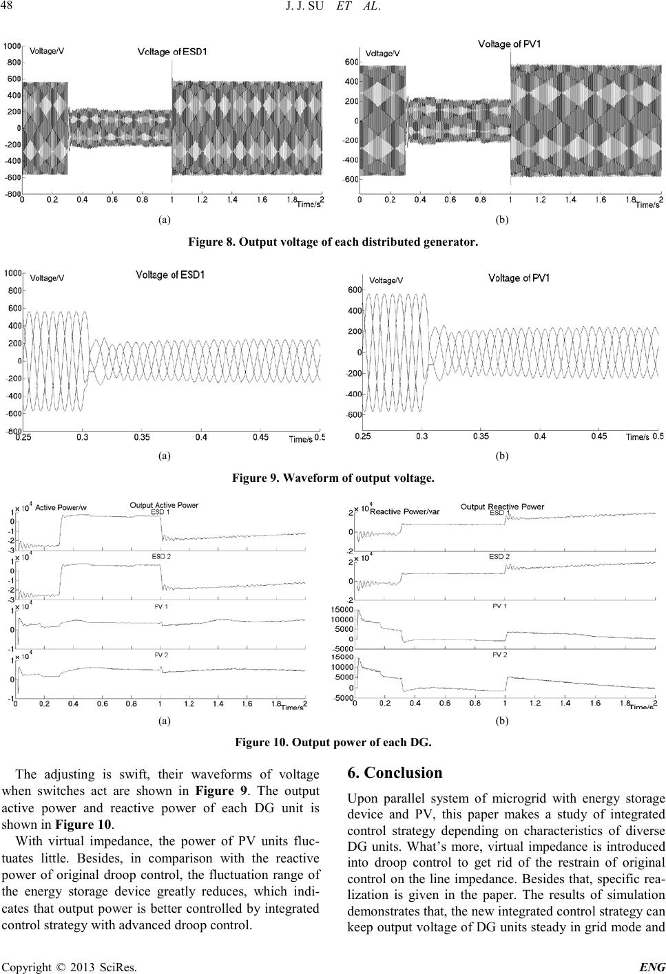 J. J. SU ET AL. Copyright © 2013 SciRes. ENG 48 (a) (b) Figure 8 . O utput v o ltage o f each di strib uted generator. (a) (b) Figure 9 . Waveform of output vol tage. (a) (b) Figure 1 0. Output power of each DG. The adjusting is swift, their waveforms of voltage when switches act are shown in Figure 9. The output active power and reactive power of each DG unit is sho wn in Figure 10. With virtual impedance, the power of PV units fluc- tuates little. Besides, in comparison with the reactive power of original droop control, the fluctuation range of the energy storage device greatly reduces, which indi- cates that output power is better controlled by integrated control strategy with advanced droop control. 6. Conclusion Upon parallel system of microgrid with energy storage device and PV, this paper makes a study of integrated control strategy depending on characteristics of diverse DG units. What’s more, virtual impedance is introduced into droop control to get rid of the restrain of original control on the line impedance. Besides that, specific rea- lization is given in the paper. The results of simulation demonstrate s that, the new int egrated contro l strateg y can keep output voltage of DG units steady in grid mode and 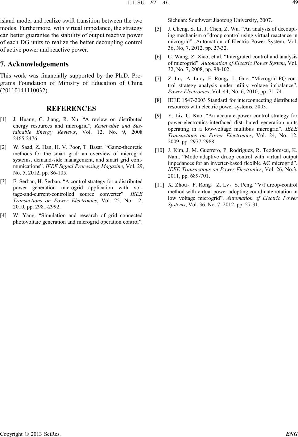 J. J. SU ET AL. Copyright © 2013 SciRes. ENG 49 island mode, and realize swift transition between the two modes. Furthermore, with virtual impedance, the strategy can better guarantee the stability of output reactive power of each DG uni ts to realize the better decoupling control of active power and reactive power. 7. Acknowledgements This work was financially supported by the Ph.D. Pro- grams Foundation of Ministry of Education of China (20110141110032). REFERENCES [1] J. Huang, C. Jiang, R. Xu. “A review on distributed energy resources and microgrid”, Renewable and Sus- tainable Energy Reviews, Vol. 12, No. 9, 2008 2465-2476. [2] W. Saad, Z. Han, H. V. Poor, T. Basar. “Game-theoretic methods for the smart grid: an overview of microgrid systems, demand-side management, and smart grid com- munications”. IEEE Signal Processing Magazine, Vol. 29, No. 5, 2012, pp. 86-105. [3] E. S erban , H. S erb an. “A control strategy for a distributed power generation microgrid application with vol- tage-and-current -controlled source converter ”. IEEE Transactions on Power Electronics, Vol. 25, No. 12, 2010, pp . 2981-2992. [4] W. Yang. “Simulation and research of grid connected photovoltaic generation and microgrid operation control”. Sichuan: Southwest Jiaotong University, 2007. [5] J. Cheng, S. Li, J. Chen, Z. Wu. “An analysis of decoupl- ing mechanism of droop control using virtual reactance in microgrid”. Automation of Electric Power System, Vol. 36, No, 7, 20 12, pp. 27-32. [6] C. Wang, Z. Xiao, et al. “Intergrated control and analysis of microgrid”. Automation of Electric Power System, Vol. 32, No. 7, 20 08, pp. 98-102. [7] Z. Lu,A. Luo,F. Rong,L. Guo. “Microgrid PQ con- trol strategy analysis under utility voltage imbalance”. Power E lectronics, Vol. 44, No. 6, 2010, pp. 71-74. [8] IEEE 1547-2003 Standard for interconnecting distributed resou r ces with electric power systems. 2 003. [9] Y. Li,C. Kao. “An accurate power control strategy for power-electronics-interfaced distributed generation units operating in a low-voltage multibus microgrid”. IEEE Transactions on Power Electronics, Vol. 24, No. 12, 2009, pp . 2977-2988. [10] J. Kim, J. M. Guerrero, P. Rodriguez, R. Teodorescu, K. Nam. “Mode adaptive droop control with virtual output impedances for an i nverter-b ased flexible AC microgrid”. IEEE Transactions on Power Electronics, Vol. 26, No.3, 2011, pp . 689-701. [11] X. Zhou,F. Rong,Z. Lv,S. Peng. “V/f droop-control method with virtual power adopting coordinate rotation in low voltage microgrid”. Automation of Electric Power Systems, Vol. 36, No. 7, 2012, pp. 27-31. |