Paper Menu >>
Journal Menu >>
 Dynamic Contact Problem for Slide Hinge Kazunori Shinohara JAXA's Engineering Digital Innovation Center (JEDI) Japan Aerospace Exploration Agency (JAXA) Sagamihara, Japan shinohara@06.alumni.u-tokyo.ac.jp Ryoji Takaki Institute of Space and Astronautical Science (ISAS) Japan Aerospace Exploration Agency (JAXA) Sagamihara, Japan ryo@isas.jaxa.jp Takeshi Akita Faculty of Engineering Chiba Institute of Technology Chiba, Japan akita.takeshi@it-chiba.ac.jp Abstract—Contact analysis can be either static or dynamic. In static contact analysis, the position on the contact surface is constant. In dynamic contact analysis, the position on the contact surface changes at every time step. In static contact analysis, the computing results (stress, strain, etc.) of contact states have been verified through the Hertz contact problem in literature. On the other hand, there has been insufficient research into dynamic contact analysis. The contact algorithm is insufficiently constructed in finite element model (FEM) discretization. The gap between two objects cannot be calculated accurately. A contact method is demanded for artificial parameters. Inappropriate setting of artificial parameters causes artificial numerical oscillations on the contact surface between objects. To develop a high-reliability satellite, we started the development of FEM contact-friction modeling techniques in this study. A dynamic contact method was realized by using the appropriate parameters required in the contact analysis. We verified the reproducibility of the physical behavior of the contact friction via numerical simulation techniques by using a computational model of the hinge joints. Keywords-FEM; Contact; Friction; Stress; Joints; Structural Analysis; Advance/FrontSTR; Dynamic Contact Analysis; Static Contact Analysis 1. Introduction This year, failures due to joints between parts have become apparent [1]-[3], as high-precision equipment of space structures are demanded. Various contaminants in the air on the ground adhere to the contacting parts of metal surfaces. These contaminants, in turn, act as a lubricant, thereby reducing the coefficient of friction. Therefore, the frictional force on the contact surface is naturally decreased on the ground. Space, however, is a vacuum, and because metal contamination does not occur in space, the friction coefficient between the metals in space increases to about 10 times that on the ground [4]. In space, the friction force causes incomplete movement at joints because of the lack of lubrication. In this study, to develop the high-precision space structure, we construct a simulation based on contact-friction finite element analysis (FEM) using Advance/FrontSTR [5]-[7]. The accuracy of the calculated results using Advance/FrontSTR is verified. To develop high-reliability satellites, we started the development of contact modeling techniques by using a high-performance computer (JSS) in this study. The contact behaviors were verified by using computational joint models of the slide hinge. 2. Contact-friction analysis [6] [8] The variable ȡ represents the density. The subscript curly brackets of variables represent object {1} and object {2}. The superscript ˆ represents the known variables. The sign · and the sign : represent the inner product of the first order tensor and second order tensor, respectively. The sign ȍ{i} represents the internal domain of objects. Signs Ȗ{1} and Ȗ{2} represent the traction boundary conditions. The non-index Ȗ represents the contact surface between objects. The sign ѭ ѭ represents nabla. The boundaries ī{1} and ī{2} represent the displacement boundary conditions. The tensor ı represents the Cauchy stress tensor. The vector g represents the gravity vector. The vectors v and v represent the velocity vector and acceleration vector, respectively. The vectors n, u, and s represent the outward normal vector, the displacement vector, and the surface traction vector, respectively. The function u* represents arbitrary weighting functions. Governing equations including moving objects consist of the force balance, the displacement boundary conditions, and the traction boundary conditions. ^`^`^` ^`^` iiiii in : vgı U (1) ^` ^`^`^` iiii on J snıˆ (2) Open Journal of Applied Sciences Supplement:2012 world Congress on Engineering and Technology 82 Cop y ri g ht © 2012 SciRes. 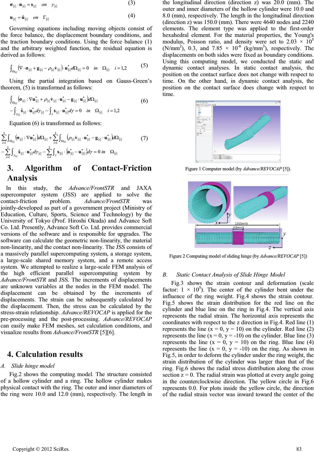 ^` ^`^`^` iiii on J snı (3) ^` ^`^` iii on * uu ˆ (4) Governing equations including moving objects consist of the force balance, the displacement boundary conditions, and the traction boundary conditions. Using the force balance (1) and the arbitrary weighted function, the residual equation is derived as follows: ^`^`^` ^` ^` ^` ^` ^` 2,10 * : : ³ :iindiiiiiii i uvgı U (5) Using the partial integration based on Gauss-Green’s theorem, (5) is transformed as follows: ^`^`^`^` ^`^` ^` ^` ^` ^`^` ^` ^` ^` ^`^` 2,10 ˆ : ** *** : : ³³ ³: iindd d iiiiii iiiiiiii i i JJ JJ U usus uguvuı (6) Equation (6) is transformed as follows: ^` ^` ^` ^` ^`^` ^`^` ^` ^` ^` ^`^` ^` ^` ^`^`^ ` ^` ^` i ii iii i iiiiii i iii indd dd i ii : :: ¦³ ¦³ ¦³ ¦³ : : 0 ˆ : 2 1 * 2 * 11 2 1 * 2 1 ** 2 1 * JJ JJ U uusus uguvuı (7) 3. Algorithm of Contact-Friction Analysis In this study, the Advance/FrontSTR and JAXA supercomputer system (JSS) are applied to solve the contact-friction problem. Advance/FrontSTR was jointly-developed as part of a government project (Ministry of Education, Culture, Sports, Science and Technology) by the University of Tokyo (Prof. Hiroshi Okuda) and Advance Soft Co. Ltd. Presently, Advance Soft Co. Ltd. provides commercial versions of the software and is responsible for upgrades. The software can calculate the geometric non-linearity, the material non-linearity, and the contact non-linearity. The JSS consists of a massively parallel supercomputing system, a storage system, a large-scale shared memory system, and a remote access system. We attempted to realize a large-scale FEM analysis of the high efficient parallel supercomputing system by Advance/FrontSTR and JSS. The increments of displacements are unknown variables at the nodes in the FEM model. The displacement can be obtained by the increments of displacements. The strain can be subsequently calculated by the displacement. Then, the stress can be calculated by the stress-strain relationship. Advance/REVOCAP is applied for the pre-processing and the post-processing. Advance/REVOCAP can easily make FEM meshes, set calculation conditions, and visualize results from Advance/FrontSTR [5][6]. 4. Calculation results A.Slide hinge model Fig.2 shows the computing model. The structure consisted of a hollow cylinder and a ring. The hollow cylinder makes physical contact with the ring. The outer and inner diameters of the ring were 10.0 and 12.0 (mm), respectively. The length in the longitudinal direction (direction z) was 20.0 (mm). The outer and inner diameters of the hollow cylinder were 10.0 and 8.0 (mm), respectively. The length in the longitudinal direction (direction z) was 150.0 (mm). There were 4640 nodes and 2240 elements. The element type was applied to the first-order hexahedral element. For the material properties, the Young's modulus, Poisson ratio, and density were set to 2.03 × 10⁵ (N/mm2), 0.3, and 7.85 × 10⁻⁶ (kg/mm3), respectively. The displacements on both sides were fixed as boundary conditions. Using this computing model, we conducted the static and dynamic contact analyses. In static contact analysis, the position on the contact surface does not change with respect to time. On the other hand, in dynamic contact analysis, the position on the contact surface does change with respect to time. Figure 1 Computer model (by Advance/REVOCAP [5]). Figure 2 Computing model of sliding hinge (by Advance/REVOCAP [5]) B.Static Contact Analysis of Slide Hinge Model Fig.3 shows the strain contour and deformation (scale factor: 1 × 10⁵). The center of the cylinder bent under the influence of the ring weight. Fig.4 shows the strain contour. Fig.5 shows the strain distribution for the red line on the cylinder and blue line on the ring in Fig.4. The vertical axis represents the radial strain. The horizontal axis represents the coordinates with respect to the z direction in Fig.4. Red line (1) represents the line (x = 0, y = 10) on the cylinder. Red line (2) represents the line (x = 0, y = -10) on the cylinder. Blue line (3) represents the line (x = 0, y = 10) on the ring. Blue line (4) represents the line (x = 0, y = -10) on the ring. As shown in Fig.5, in order to deform the cylinder under the ring weight, the strain distribution of the cylinder was larger than that of the ring. Fig.6 shows the radial stress distribution along the cross section z = 0. The radial strain was plotted at every angle going in the counterclockwise direction. The yellow circle in Fig.6 represents 0.0. For plots inside the yellow circle, the direction of the radial strain vector was inward toward the center of the Cop y ri g ht © 2012 SciRes.83 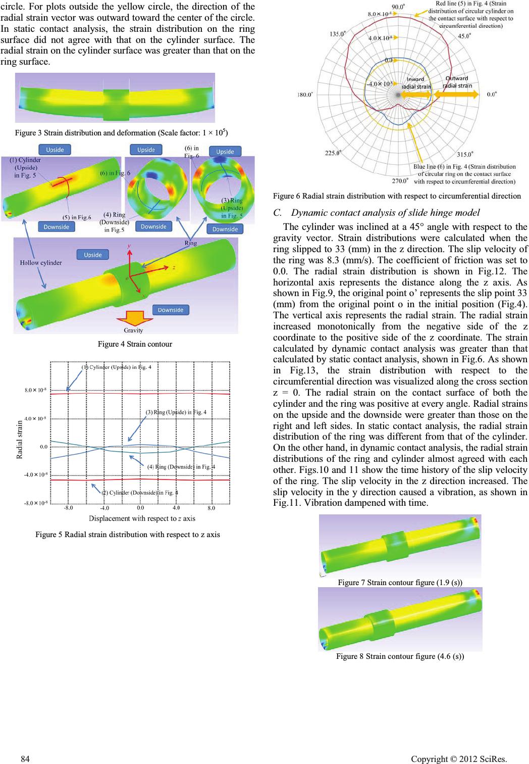 circle. For plots outside the yellow circle, the direction of the radial strain vector was outward toward the center of the circle. In static contact analysis, the strain distribution on the ring surface did not agree with that on the cylinder surface. The radial strain on the cylinder surface was greater than that on the ring surface. Figure 3 Strain distribution and deformation (Scale factor: 1 × 10⁵) Figure 4 Strain contour Figure 5 Radial strain distribution with respect to z axis Figure 6 Radial strain distribution with respect to circumferential direction C.Dynamic contact analysis of slide hinge model The cylinder was inclined at a 45° angle with respect to the gravity vector. Strain distributions were calculated when the ring slipped to 33 (mm) in the z direction. The slip velocity of the ring was 8.3 (mm/s). The coefficient of friction was set to 0.0. The radial strain distribution is shown in Fig.12. The horizontal axis represents the distance along the z axis. As shown in Fig.9, the original point o’ represents the slip point 33 (mm) from the original point o in the initial position (Fig.4). The vertical axis represents the radial strain. The radial strain increased monotonically from the negative side of the z coordinate to the positive side of the z coordinate. The strain calculated by dynamic contact analysis was greater than that calculated by static contact analysis, shown in Fig.6. As shown in Fig.13, the strain distribution with respect to the circumferential direction was visualized along the cross section z = 0. The radial strain on the contact surface of both the cylinder and the ring was positive at every angle. Radial strains on the upside and the downside were greater than those on the right and left sides. In static contact analysis, the radial strain distribution of the ring was different from that of the cylinder. On the other hand, in dynamic contact analysis, the radial strain distributions of the ring and cylinder almost agreed with each other. Figs.10 and 11 show the time history of the slip velocity of the ring. The slip velocity in the z direction increased. The slip velocity in the y direction caused a vibration, as shown in Fig.11. Vibration dampened with time. Figure 7 Strain contour figure (1.9 (s)) Figure 8 Strain contour figure (4.6 (s)) 84 Cop y ri g ht © 2012 SciRes. 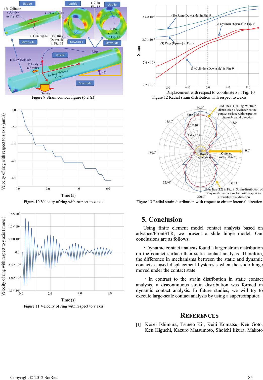 Figure 9 Strain contour figure (6.2 (s)) Figure 10 Velocity of ring with respect to z axis Figure 11 Velocity of ring with respect to y axis Figure 12 Radial strain distribution with respect to z axis Figure 13 Radial strain distribution with respect to circumferential direction 5. Conclusion Using finite element model contact analysis based on advance/FrontSTR, we present a slide hinge model. Our conclusions are as follows: ࣭Dynamic contact analysis found a larger strain distribution on the contact surface than static contact analysis. Therefore, the difference in mechanisms between the static and dynamic contacts caused displacement hysteresis when the slide hinge moved under the contact state. ࣭In contrast to the strain distribution in static contact analysis, a discontinuous strain distribution was formed in dynamic contact analysis. In future studies, we will try to execute large-scale contact analysis by using a supercomputer. REFERENCES [1] Kosei Ishimura, Tsuneo Kii, Keiji Komatsu, Ken Goto, Ken Higuchi, Kazuro Matsumoto, Shoichi Iikura, Makoto Cop y ri g ht © 2012 SciRes.85  Yoshihara, and Masaharu Tsuchiya, Shape Prediction of Large Deployable Antenna Structure on Orbit, Transactions of the Japan Society for Aeronautical and Space Sciences, Aerospace Technology Japan, 10(2012). [2] Hiroshi Kitahara, Kiku-6's Unsuccessful Injection into GEO: Then and Afterwards, The Journal of the Institute of Electronics, Information, and Communication Engineers 80(1997), pp. 570-575. [3] Hiraku Sakamoto, Nicholas Ragosta, and Mori Osamu, Finite-element Analysis of Membrane Deployment and Its Validation, Proceedings of 55th Space Sciences and Technology Conference, paper No.1B08, (2011). [4] Donald H. Buckley, Friction, Wear and Lubrication in Vacuum, NASA-SP-277, 1971. [5] AdvanceSoft. Co., Ltd., http://www.advancesoft.jp/. [6] Xi Yuan, Theory reference on nonlinear analysis of Advance/FrontSTR Ver.3.0, Advance Simulation, vol. 4, pp. 6–59, 2010. [7] FrontISTR, http://www.ciss.iis.u-tokyo.ac.jp/. [8] Klaus Jurgen Bathe, Finite Element Procedures, New Jersey, Prentice Hall, 1995. 86 Cop y ri g ht © 2012 SciRes. |

