Engineering, 2013, 5, 56-60
http://dx.doi.org/10.4236/eng.2013.51009 Published Online January 2013 (http://www.scirp.org/journal/eng)
Analyzing Some Behavior of a Beam with Different Crack
Positions Transversely inside It
Behrooz Yazdizadeh
Department of Mechanics, Kerman Branch, Islamic Azad University, Kerman, Iran
Email: behyazd@iran.ir
Received October 4, 2012; revised November 6, 2012; accepted November 25, 2012
ABSTRACT
Vertical displacement, critical Euler buckling load and vibration behavior of a cracked beam are considered in this re-
search. The crack inside the beam is placed in different positions and results compared for each crack position. On first
Eigenvalue of free vibration results, there is a border that first Eigenvalue of free vibration does not change if center of
crack is located on that border, and after that border, the first Eigenvalue of free vibration is increased that is a counter-
example relation of critical Euler buckling load and first Eigenvalue of free vibration.
Keywords: Crack; Mesh; Vibration; Euler Buckling; Displacement
1. Introduction
Fracture mechanics, was originated by Wieghardt and
Inglis [1]. Both independently showed that cavities and
flaws in continuum materials act as stress concentrators
which, in the limit of sharp edges (cracks), produce infi-
nite stress at the tip [2]. A fairly thorough description of
the approaches for solving the crack problems is made by
many researchers [3-6]. These were the first attempts to
bring closer the theories of fracture mechanics (FM) and
continuum mechanics (CM). About the same time, the
Finite Element Method (FEM) and digital computers
dashed into the engineering community as a gifted means
for quantifying solutions in structural and solid mechan-
ics. Naturally, fracture mechanic researchers implement-
ed their FE methods, while continuum mechanic re-
searchers implemented theirs [7].
Over the years, the finite element technique has been
so well established that today it is considered one of the
best methods for solving a wide variety of practical
problems efficiently and is more and more feasible, pro-
vided that finite element (FE) models can be shown to be
correct [8]. It can be used for the solution of any problem
simply by changing the input data [9].
A lot of effort has been spent in the last 30 years to
investigate and treatment the observed drawbacks of (FE)
method [10] and Finite element analysis is one of the
usual ways to solve crack problems.
In this research, some beam characteristic behavior
comparing with each other in different crack Positions
inside the beam. These comparing consist of maximum
vertical displacement under simple bending, first mode
first Eigenvalue of free vibration and critical Euler buck-
ling load.
Critical Euler buckling load for single beam-columns
can be evaluated from analytical expressions. These so-
lutions, as given for various boundary conditions, follow
the first analytical method given by Euler [11] for pre-
dicting the reduced strengths of slender columns. The
finite elements method can be easily implemented for
beam elements without cracks since the stiffness and
generalized geometrical stiffness matrices of a non-
cracked beam are already commonly known (for example
in [12]). However, the situation essentially changes if the
structural elements are transversely cracked. Two dimen-
sion (2D) or three dimension (3D) finite element ana-
lyzes must be implemented in order to achieve a com-
plete model of the structure. When studying the elastic
Euler buckling load of a column, it is necessary to deter-
mine the maximum load at which the structure remains in
equilibrium at the deformed position.
Stress intensity factor, normal, and shear stresses (at the
tip of the crack) are calculated for simple cracked beam
under vertical pressure before [13].
Here we examine changes of some parameters of a
beam with different crack position inside of it for con-
clusion that whether crack position has an important role
to change the vertical displacement, first Eigenvalue of
free vibration and critical Euler buckling load or not.
2. Material and Methods
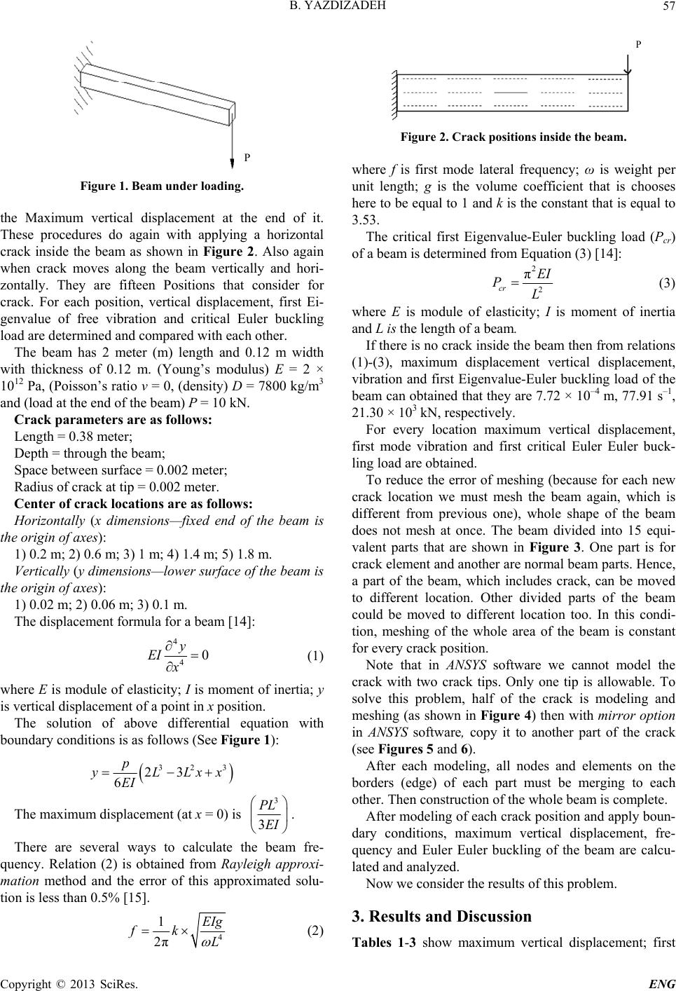
Consider a beam as shown in Figure 1. This beam
loaded with a vertical load at end of it then calculating
C
opyright © 2013 SciRes. ENG